IC 653 Report on the Pfalz (Type DXII) Single Seat Fighter, Oct. 1918
THE PFALZ SINGLE-SEATER FIGHTER.
160 H.P. MERCEDES ENGINE.
(Described in Flight Magazine)
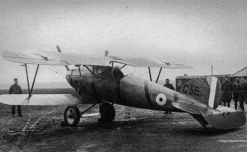
In our issue of April 18th, 1918, we published some photographs and a brief description of the Pfalz single-seater fighter. We have, since then, by the courtesy of the authorities, been permitted to examine in detail, and sketch, one of these machines exhibited at the Enemy Aircraft View Rooms. Owing to the fact that several of these machines have been captured, there is available a great number of parts, so that it has been possible to ascertain the internal construction of practically all the details, many of which are very interesting. As the Pfalz is, constructionally, rather different from the general run of German machines, we propose to devote a considerable space to it, hoping that the information thus conveyed will be found both useful and interesting to all concerned in the production and use of aircraft. - ED.]
As a type the Pfalz belongs to the single-seater fighter class with low-resistance body, which during the last twelve months or so has been given more attention in Germany than ever before. Up till that time German designers had, generally speaking, troubled little about cutting down head resistance on their machines, trusting, presumably, to their high-power water-cooled engines to pull them through. As, however, the machines of the Allies increased in speed and climb it became obvious that something more than mere engine power would be required to cope with the constantly increasing demands, and once this was realised several German firms began to look around for ways and means of improving the performance of their machines. Among these were the Albatros firm, which turned out some single-seater fighters, incorporating the Nieuport type wing bracing and the semi-monocoque body of stream-line shape. It was on machines of this type that the pilots of the "Richthofen Circus" did much of their fighting. Then there was the Roland fighter, in which attempts were also made at stream-lining the body, but which went rather farther and made the body so deep as to serve directly as a support for the top plane. Finally we have the Pfalz, in which stream-lining has been carried a little farther still, inasmuch as the attachment of the lower wings takes the form of wing roots formed integrally with the body and the object of which is presumably to avoid sharp corners at the juncture of wings and body. The wing arrangement of the Pfalz also differs slightly from that of the Albatros in that the inter-plane struts do not come to a point on a single lower spar, but are separate at their lower ends by a short horizontal piece, evidently so as to enable the struts to take care of the twisting moment due to the travel of the c.p. better than can be done with a point attachment.
An examination of the Pfalz biplane gives the impression, also conveyed in the accompanying drawings, of very low resistance indeed, and with an engine of 160 h.p. one naturally expects the machine to have an excellent speed. Tests carried out in this country do not, however, confirm this first impression, and the following particulars of performance can only be regarded as disappointing in view of the promising appearance of the Pfalz, and this is another proof of the difficulty of judging "by eye" the merits or otherwise of a machine.
According to the official report on the tests the following data were established :-
Pfalz Scout, No. G. 141.
Engine 160 h.p. Mercedes.
Number of crew One.
Military duty Fighter.
Propeller Axial, Berlin.
Total military load 281 lbs.
Climb to 10,000 ft. In 17 mins. 30 secs.
Speed at 10,000 ft. 102 1/2 m.p.h.; revs., 1,400 r.p.m.
Rate of climb 360 ft./min.; revs., 1,310 r.p.m.
Climb to 15,000 ft. In 41 mins. 20 secs.
Speed at 15,000 ft. 91 1/2 m.p.h.; revs., 1,325 r.p.m.
Rate of climb 100 ft./min.; revs., 1,280 r.p.m.
Estimated absolute ceiling 17,000 ft.
Greatest height reached 15,000 ft. in 41 mins. 20 secs.
The total military load is made up as follows :-
Riot 180 lbs.
Two Spandau guns 70 "
Dead weight 31 "
Total 281 "
Weight per sq. ft. 8.56 lbs.
Weight per h.p. 12.84 "
Total weight of machine, fully loaded 2,056 lbs.
Weight of machine, bare, with water 1,580 lbs.
Military load, less crew 101 "
Crew, as above 180 "
Petrol, 21 1/2 galls 155 "
Oil, 4 galls. 40 "
Total 2056 "
The first question that naturally comes to mind after studying this table of performances is. What is the reason for this poor performance, for it can scarcely be termed otherwise. Some of the figures given in the table may help to furnish the solution, although after perusing them there are still several remaining unanswered. For instance, the wing loading is somewhat high, but certainly not so much so as to account by itself for the low maximum speed and low rate of climb. The body appears to be of good streamline form, but against this must be placed the fact that the maximum cross sectional area is comparatively large, owing to the deep body reaching nearly to the top plane. As regards the wing bracing, this is simple enough as far as concerns the number of wires and struts, but the cables are not faired, and as they are of rather large diameter, their resistance at maximum speed may reasonably be assumed to be fairly high. If, however, the detrimental resistance is considerable, the wing resistance is probably no less so, the wing section being of the deeply cambered type so favoured by German designers, and which has, generally speaking, a somewhat high drag, although its lift is good. We have for some time held the opinion that German designers were deliberately employing deeply cambered sections with a view to obtaining better performance at altitudes, but we are bound to admit that the official tests of the Pfalz scarcely appear to bear out this contention. We would strongly urge that the authorities have tests carried out at the N.P.L. on all the German wing sections of which data are available, as the publications of the results of such tests would be of the greatest interest. We do not for a moment imagine that the sections would reveal any superiority over those more commonly employed by the Allies, but some interesting facts might nevertheless be brought to light, which might be of use to our own designers, if only as a warning regarding what not to do.
Constructionally the Pfalz single-seater is even more interesting, showing, as it does, considerable departures in detail design from other German makes of the same class, on which its fundamental arrangement is evidently founded. This refers especially to the Albatros fighter single-seater, which is characterised by the same main features, such as large top plane and small bottom plane, one pair of interplane Vee struts on each side, ply-wood streamline body, &c. Apart from minor differences in shape, the Pfalz designer has chiefly struck out along original lines in the construction of the body. Whereas in the Albatros one finds the same oval formers connected by longitudinal rails, the manner of applying the three-ply covering is totally different in the two machines. In the Albatros the ply-wood is put on in small pieces covering only a bay or so; the covering of the Pfalz is in the form of long strips spirally laid on, the strips of the two layers forming an angle with one another.
In Fig. 1 is shown the general arrangement of the Pfalz body. There are in all eight longerons, it will be noticed-one at the top, one at the bottom, one half-way up on each side and four at what would be the corners in a rectangular section body. These longerons run the whole length of the body, with the exception of the top one, which is terminated just to the rear of the engine, and are attached to the formers as shown in the sketch, Fig. 2. The longerons are stop-chambered so as to leave them solid where occur the formers, into which they are sunk and secured by a wood screw. The formers themselves are built up of smaller pieces of spruce, lap-jointed and covered each side with a facing of three-ply wood.
Reference has already been made to the fact that wing roots are formed integrally with the body. These roots can be seen in the side view, Fig. 1; and account for the peculiar shape of formers III and IV. Judging by these formers the cross-sectional area is unduly increased at this point, although this may be partly made up for by the shape of the-ply-wood covering, which merges the lines of the lower plane into the curves of the body. This is illustrated in the two sketches, Fig. 3. It is, perhaps, open to doubt whether or not this elaborate arrangement is worth while. Constructionally it must necessarily entail considerable extra work, and aerodynamically it does not look as neat and efficient as the Albatros way of doing the same thing by frankly letting the bottom plane abut directly on the curved sides of the body.
Fig. 4 is a perspective view of the Pfalz body, and serves in conjunction with Fig. 1 to explain the general arrangement of formers and longerons. Some of the formers, it will be noticed, are sloped in relation to the others. Thus, for instance, the former in the neighbourhood of the pilot's seat slopes back so as to bring it approximately into line with the rear chassis struts, while rigidity is lent to the front portion of the body by sloping one of the formers carrying the engine bearers until its top meets the top of the next former. In this point also the formers are joined to the front struts carrying the top plane, while one of them serves, at the point of attachment of the bottom corner longeron, to transmit the load from the front chassis struts.
One of the difficulties of monocoque body construction has always been that you cannot bend three-ply sheet over a double curvature. That is to say, in sheet form the three-ply will bend willingly to the curvature of the converging sides of a flat-sided body; but as soon as the sides are no longer flat but have a curvature, however slight, three-ply in sheet form cannot be employed. In the Albatros this difficulty is overcome by using small sheets, covering only one bay, and forming in reality, although it is not noticeable, a series of straight bays. In the Pfalz a different method has been employed. The body covering consists of two layers of three-ply, each less than 1 mm. thick. The plywood is evidently manufactured in sheets, and before applying to the body is cut up into parallel strips of about 3 to 4 ins. the width apparently varying considerably throughout the body. The first layer of three-ply is then put on by bending it diagonally around the body, attaching it by tacking to the various longerons, en route, and cutting each narrow strip at the top and bottom longerons, which form the terminals so to speak of the three-ply covering, which is thus applied in two halves. The second layer of strips is then laid on top of the first, but at a different angle, to which it is secured by glueing, and finally tacked to the longerons. The inside layer is reinforced, in the front portion of the body, by glueing tapes over the joint between adjoining strips of plywood. This and other details are shown in Fig. 5. In order to spread a joint in the ply-wood over as large an area as possible the joint is made, as shown, in a sort of saw tooth or serrated butt joint style. This, in brief, is the fundamental construction of the Pfalz body, and differs considerably from other makes. As to its efficiency - we cannot speak. The weight at any rate, judging from the comparatively low total weight of the machine, can scarcely be any greater than the girder type of body, but as regards strength we have no information. We have heard it said that the Pfalz machines have a habit of breaking their bodies just aft of the pilot's cockpit, but for the accuracy of this statement we cannot vouch. As a compromise between sheet three-ply covering and true monococque construction the Pfalz method would appear to have certain advantages.
At the stern the Pfalz body terminates, as shown in the illustrations in our last issue and further illustrated in detail in Fig. 6, in a somewhat elaborate framework of wood, which performs the various functions of forming supports for the tail plane, tail skid, and vertical fin with its rudder. The design of this part of the body must have provided some pretty problems in projection drawing, and one is inclined to think that a little less rigid economy in metal fittings might have resulted in a considerably simpler design. The second former from the stern is, it will be seen from Fig. 6, sloped backwards to form the leading edge of the vertical fin, and is reinforced above the body with other pieces of' wood to give it a rounded edge. The last former is in duplicate, its front half extending upwards to form a member of the fin, while the other half terminates just above the body and serves chiefly as a support for the short length of spar to which the front spar of the tail plane is attached. Between these two formers and sloping so as to form in side view a cross, are another two formers, built up in much the same manner as the main body formers. The angle formed by one of these and the longeron accommodates the leading edge of the small plane permanently fixed to the body, while the point of intersection of the two formers supports a short transverse cylindrical piece of wood, around which is wrapped the shock absorbers for the tail skid. The details of both these joints are shown in the sketches of Fig. 6. The small tail plane root is covered, on the actual machine, with plywood, but this has been omitted in the sketch in order to better show the constructional details.
The tail plane itself is in one piece, and fits into the slot provided for it in the body. The manner in which it is secured after being placed in its slot will be clear from an inspection of Fig. 7. The front spar rests in the slot in the body, and is secured against lateral tilting by a steel band on each side, overlapping the butt joint between the front part of the rib and the tail plane root, as shown in Fig. 7. The rear spar of the tail plane is locked in place by two long bolts and a stud. The two bolts are placed one on each side of the stern, as indicated in the sketch in Fig. 7, while the stud passes through a lug welded on to the extreme rear of the steel shoe surrounding the heel of the fuselage into another lug near the foot of the stern post. The whole tail plane with its elevator can therefore be removed by undoing five nuts, and, of course, the connections in the elevator control cables.
As regards the tail plane and elevator themselves, these are constructed along more or less standard lines and do not present any especially remarkable features. It has already been pointed out that the tail plane appears at first sight to have been put on "upside down," having a flat top surface and a convex bottom surface. The reason for this is not apparent, but it is possible that the disposition of the various weights and surfaces is such that there is either a lift-weight couple or a thrust resistance couple or both; and that this section tail plane has been employed to equalise such couples. However, in a later machine captured and now at the Enemy Aircraft View Rooms the shape of the tail plane had been altered to a symmetrical section, so that it would appear that the "inverted" section has either been found unsatisfactory in practice or the reasons for its employment removed in a later design. Structurally the tail plane is built up of spruce spars with ribs having ash flanges and poplar webs. The inner ribs an covered with three-ply to give extra rigidity for attachment to the body. The front spar is of I section while the rear spar is channel section, with recesses top and bottom for forming a flat surface with the rib flanges. There is no internal wire bracing, the necessary rigidity being obtained by means of diagonal ribs and by plates of three-ply placed over the joints between-ribs and spars. The leading edge, which is also bent back to form the tips of the tail plane, is laminated as shown in Fig. 7, and is lightened by spindling between the ribs. The laminations are probably steamed so as to be easily bent to form the rounded corners of the tail plane.
The elevator, owing to the fact that the rudder has no downward projection, is in one piece, and is built up in a manner similar to that of the tail plane. Its leading edge is formed by a box spar, and the ribs are similar to those of the tail plane. The attachment of the ribs to the trailing edge is somewhat unusual. Instead of the flanges of the ribs passing over the trailing edge they are thinned down and pass into a slot in the trailing edge as shown inset in Fig. 7. They are then secured in place by a small metal clip. The slots in the trailing edge appear to have been made with a circular cutter of about 3 in. diameter, the ends of the rib flanges being placed where the slot is deepest. The elevator hinges are formed by forked bolts passing through the rear spar of the tail plane, and corresponding with eye bolts through the leading edge of the elevator.
The elevator crank levers are of a type frequently found on German machines. The crank itself is of streamline section, and is welded to a channel section base plate surrounding three sides of the leading edge. Another base plate of similar shape, but made of lighter gauge, is slipped over the leading edge from the front, and forms a washer for the hinge bolt, which passes through the leading edge at a point coincident with the crank lever. The attachment of the elevator and rudder cables to their respective cranks is in the form of a ball and socket, joint, or, more correctly speaking, the ball portion of it is not a complete ball but a slice of a sphere, formed integrally with the bolt passing out of the socket into the barrel of the wire-strainer. The socket, and also the ball have a flat formed on one side so as to prevent the ball from turning in the socket. Behind the ball a small split-pin passes transversely through the socket, thus preventing the ball from dropping out of the socket when the control cables are removed. The socket is kept filled with grease.
The rudder, which, as already pointed out, is placed wholly above the elevator, is built entirely of steel tubing. The ribs are joined, not directly to the rudder post, but to a collar of very light gauge, which is in turn pinned and braced to the rudder post. The object of this construction probably is to avoid weakening the rudder post by welding, since all the rudder ribs can then be welded to their collars on a jig, the rudder post being inserted afterwards and the collars pinned in place. The rear end of the ribs is joined direct to the trailing edge by welding. The method of tapering the rib tubes down towards the trailing edge is different from anything we have yet seen on a German machine. A vertical slice is taken out of one of the tubes, and the edges thus formed are pushed over the other tube of the rib as indicated in Fig. 8, the two tubes being held together by short welds at intervals.
The foot of the rudder post rests in a cup or shoe on the trailing edge of the vertical tin, while additional hinges are provided at intervals. The form these hinges take is shown in Fig. 8. To prevent the rudder post from sliding up and down a collar is placed above and one below each hinge. To these collars are welded two U-shaped rods around which is wrapped fabric in order to form an air tight joint at the points where the hinge pierces the rudder covering. This is also shown in Fig. 8. The fabric wrapping has been omitted for the sake of clearness.
The tail skid is of somewhat unusual shape, as shown in the right-hand sketch of Fig. 7. Owing to the fact that there is no vertical fin below the body of the Pfalz, and no downward projection of the rudder, it has been possible to reduce head resistance of skid by making it horizontal for the greater part of its length, with just a downward curve at the rear to give greater clearance for the tail plane. The skid is pivoted on a bolt passing through a lug on the heel of the fuselage. Its free end is sprung by rubber cord from the short cylindrical piece of wood already referred to, and shown in Fig. 6. This attachment looks remarkably weak - a piece of wood, slotted at its ends to fit over the cross formed by the two sloping body formers. Yet in all the captured specimens of Pfalz machines that we have had an opportunity to examine, this particular member has never been broken, so that one can only infer that it is stronger than it appears. As to the skid itself, it is built up of ten laminations of wood, each about 5 mm. thick. At the rear the skid is provided with a sheet metal shoe to protect it against wear.
The seating accommodation of the Pfalz does not present any special features, except, perhaps, that the pilot's cockpit is quite roomy considering the area of the cross section at this point. This is, of course, a consequence of the peculiar body construction, which leaves, for a given cross section, more space inside than is possible when employing the girder type fuselage with rectangular main structure and the fairings added afterwards. Thus, in the case of a circular cross section, for a diameter of 3 ft. the inscribed square is only about 2 ft., while with the monocoque construction the whole circle is available for the accommodation of the pilot. This is another way of saying that the cross sectional area of a body of rounded section can be kept smaller with monocoque construction than with girder-cum-fairing construction, resulting in lower head resistance.
The seating itself is of the usual type, and was indicated in Figs. 1 and 4 of our July 25th issue. The front edge of the seat is supported on the sloping former, while the rear of the seat rests on a transverse member supported on a small false former slightly farther aft. Needless to say the pilot is equipped with a safety belt, which in the Pfalz is in the form of webbing, attached as shown in Fig. 9, to the longerons via a short length of coil spring.
The Pfalz controls are shown in Fig. 10. A tubular control lever, forked at its lower end, is attached to a longitudinal rocking-shaft, which carries at its front end the transverse cranks for the aileron controls. In connection with these it should be remembered that ailerons are fitted to the top plane only, hence two cables pass from each end of the crank and around pulleys, one of them being what might be termed the positive cable, running through the lower plane, over pulleys, and to the aileron crank; the other being the return or equalising cable running across the body through the opposite lower plane, over a pulley, and to the opposite aileron.
As is now general practice, means are provided for locking the elevator in any desired position. The manner of doing this in the Pfalz will be evident from an inspection of Fig. 10. The collar carrying the oaileron control cranks has welded to it a vertical forked lug, a bolt through which forms the pivot for a hinged stay rod, terminating at the top in a flat, curved, slotted strip, which may be locked in any position by means of a locking disc of aluminium. At its upper end the control column has welded to it two handles, bound with cord, of which the left is rotatable and operates the throttle much after the fashion of a motor cycle. Centrally placed are two triggers operating the two synchronised machine guns via Bowden cables. The handle is shown in Fig. 11. This sketch, it may be pointed out, has been drawn from the port side in order to better show the twisting handle, while the general sketch of the controls is drawn as seen from the starboard side.
The rudder bar of the Pfalz presents some rather unusual features. Thus the rudder cables are anchored to forked lugs on the front of the foot bar, through which they pass, and issue from the rear of the bar through channel section guides which act, when the foot bar is moved to the extremity of its travel, as quadrants for the cables. The object of this rather complicated arrangement is hot clear unless it has been done in order to get the forked lugs working in compression instead of in tension. The foot rests are in the form of flat forks inserted in sockets in the foot bar and provided with adjustment for length to suit individual pilots.
Where the rudder and elevator cables issue from the interior of the body they pass through small sheet steel plates carrying a steel tube fitted with a copper tube liner to protect the cables against wear. Internal and external views of one of these fittings are shown in Fig. 12.
The engine a 160 h.p. Mercedes is mounted in the nose of the body on two longitudinal bearers supported by four main formers. The details of the mounting do not call for any comment, and the general arrangement of the engine mounting will be sufficiently clear from Figs. 1 and 4. The main petrol tank is carried in the bottom of the body, resting on the spar roots of the lower plane built into the body as a permanent fixture. The usual hand-operated pressure pump and an engine-driven pump are provided for forcing the petrol from the main tank up into the service tank built into the top plane. The oil tank is carried by the side of the engine. The nose of the machine is rounded off, and terminates in a "spinner" fitted over the propeller boss, thus forming a very smooth entry for the air. Near the nose of the machine there are two scoops, that on the port side carrying air into the engine housing, while the scoop on the starboard side has a tube running to an opening in the crank case, which is ventilated by this means. These features, as well as the neat inspection doors provided in convenient places on the front part of the body, are shown in Fig. 13. The sketches are, we think, self-explanatory.
The undercarriage is of the Vee type, with struts of streamline section steel tube. The struts look somewhat spidery, being of rather small dimensions as regards their section. The major axis of the section is 48 mm., and the maximum thickness of the strut, occurring fairly far back, is 30 mm. The fineness ratio is therefore very low. The attachment of the chassis struts to the body is of interest. The rear struts are bolted, as shown in detail in Fig. 15. to an I section steel bracket built into the wing roots on the body. Thus the landing shocks are transmitted from this strut via the bracket to the fixed rear spar and its former, and to the sloping former surrounding the pilot's seat. The upper ends of the front struts are welded to elongated base plates of heaw gauge, which serve as lugs for the chassis bracing cables. In order to distribute landing shocks over a larger area a steel band is passed underneath the bottom of the body, so that the whole bottom part of the former to which the struts are attached rests in the loop of this strap. The arrangement is illustrated in Fig. 15.
The apices of the chassis Vees are connected by two cross struts, one in front and one behind the axle. As a matter of fact it is hardly correct to term the rear one a strut in the ordinary sense of the word, as it consists of short lengths of solid wood tapered to fit the steel socket attaching it to the chassis struts, the remainder of its length being made up of a thin strip of wood forming the top surface of the trailing edge, while its bottom surface is in the form of a sheet of three-ply passing under the axle to the front cross strut. The latter is a wood strut spindled out to a "D" section, and tapered at the ends to fit the tapered steel sockets which connect it by means of bolts to the chassis struts. The top of the streamline casing around the axle thus formed is a hinged lid of aluminium, which, as the axle moves up and down when the machine is running along the ground, opens and closes, lying of course, snugly against the rear cross strut when the axle is relieved of its load as the machine leaves the ground, thus forming a good stream-line section with, it is to be presumed, a fairly low head resistance. Cross bracing of the chassis is in the front bay of the struts only, and is in the form of stout stranded cable. As in the case of the wing cables, no stream-lining has been attempted, a feature fairly typical of even modern German machines.
The shock absorbers are in the form of cords which as regards outward appearance might easily be mistaken for rubber cord, but which on closer examination, are found to be spiral springs, one inside the other, enclosed in a woven cover similar to those employed for covering stranded rubber cords. These springs are wrapped around the apex of the chassis Vee and around the axle, and are prevented from slipping up along the chassis struts by lugs welded to the struts. Two lugs higher up serve as anchorage for the short loop of stranded cable which limits the travel of the axle. This length of cable is enclosed in a cover, as shown in Fig. 15, to protect it against wear. The tubular axle is a fairly large diameter - 55 mm., to be exact; but we have not been able to ascertain of what gauge the tube is made. The details of the undercarriage are shown in the perspective sketches of Fig. 15 and in section in Fig. 14.
FUNDAMENTALLY the Pfalz single-seater belongs to the type frequently termed by the Germans a one-and-a-half-plane, that is to say, it is a machine having a larger top plane and a smaller bottom plane. The type was, as is of course well known, originated by the French Nieuport firm, and the first machine of this type, if not actually making its appearance, was at any rate contemplated, before the outbreak of war. Since then, although comparatively recently, the enemy has copied the type fairly extensively, chiefly in the Albatros single-seaters and in the make at present under review. Aerodynamically this arrangement of the planes is of advantage on account of the fact that in a biplane the lower plane is the less efficient, and that therefore the more of the total surface is formed by the top plane the better the overall efficiency. Practically also certain advantages attend the arrangement. The effect of the smaller lower chord is twofold. The gap between the planes need not be so great as in the case of a biplane having both planes of the same chord, and for a given fuselage depth the top plane may therefore be placed at a smaller height above the top of the body, resulting in a better view forward. Again the smaller bottom chord does not obstruct the view downward to the same extent as does a plane of larger chord. Thus the "one-and-a-half-plane" forms a good compromise between the lighter structure of a biplane and the good visibility of the "parasol" monoplane, which latter is probably unsurpassed as a fighter as far as obstructing the view in all directions to the smallest extent is concerned.
In the design of its wing structure the Pfalz shows several interesting features. The outward slope of the struts connecting the body with the top plane was originated, we believe, by Sopwiths in their "one-and-a-half-strutter," while the Vee form inter-plane struts are typically Nieuport. Constructionally, however, the Pfalz is a good deal different in both these features, The Vee struts are not strictly speaking placed in the form of a letter V, as they do not quite meet in a point on the lower plane, which has two spars instead of the single spar employed in the original Nieuport. The object of having two spars is evidently to provide a more rigid structure better capable of resisting the twisting moment due to the travel of the centre of pressure. Owing to the fact that the inter-plane struts do not come to a point, incidence wires should be employed, but in their stead the struts are so built up as to form the bottom of a solid U which lends to the lower ends of the struts the rigidity usually provided by incidence wires. The same applies more or less to the body struts, which, as was shown in the illustrations published in our issue of July 25th, are in the form of an inverted, flattened U with its cross member adjoining the upper plane. Here, again, the construction of the struts has been designed to perform the function of incidence wires. While on the subject of these struts, attention may be drawn to a somewhat unusual arrangement of the transverse bracing cables. Generally these run from port top rail to top of starboard body struts and vice versa. In the Pfalz, however, this arrangement has been discarded and the arrangement indicated in Fig. 16 substituted. The cross wiring does not, it will be seen, run over the top of the body at all. Instead the cables from the upper ends of the struts on one side run to the root of the bottom- plane on the same side. The body struts pivot around their attachment to the body, and any lateral displacement of the top plane would therefore result in a raising of one side or the other with a consequent tightening of the corresponding cables. From a practical point of view this arrangement of the cables would appear to possess considerable merits. The crossing of the cables above the body generally necessitates piercing of the top covering, which in most machines is raised considerably above the top longerons, to which the lower ends of the cables are usually anchored. These wires are therefore as a rule difficult to get at, and from a rigger's point of view at any rate, the Pfalz arrangement appears preferable. Then again wires crossing above the body frequently interfere with the placing of the machine guns, or with the sighting tube and other accessories. Aerodynamically, it is true, the Pfalz arrangement is at some slight disadvantage, inasmuch as the length of cables exposed to the air is greater than in the case of cables crossing above the body. When, however, as in the Pfalz, the struts are designed to do away with incidence wires the total length of cables is probably no greater, and so, on the whole, one is inclined to consider the arrangement worth while.
The general arrangement of the Pfalz wings is shown in Fig. 19. Ailerons, it will be seem, are fitted to the top plane only, as is almost universal practice in Germany. They are hinged to a false spar, and have their crank levers working in slots in the plane, another feature characteristic of enemy machines. This part of the' wing is reinforced extensively by the use of three-ply wood. As shown in the drawing, the petrol service tank is built into the top plane, as is also the radiator, which is provided with a shutter that can, owing to the low placing of the top plane, be operated direct from the pilot's seat, a handle projecting aft from the radiator being provided for this purpose. This central portion of the top plane is also reinforced by a covering of three-ply.
The two wing sections of the Pfalz are shown in Fig. 20. The lower section is not, it will be observed, an exact geometrical reduction of the upper one, the trailing portion of its lower surface being more in the nature of a reversed curvature than is the case with the top section. The difference does not, however, appear to be great. The maximum camber of the sections appears to be smaller than one usually finds on German machines. At the same time the camber is very considerable for a machine intended for fast flying, and it is possible that the wing section is, at any rate partly, responsible for the inferior performance of the Pfalz.
The wing spars of both planes are of the box form, although not, as indicated in the sections of Fig. 20, made up in the usual way of two channel sections joined by a hardwood tongue and grooves. The flanges of the spars are of spruce, and of the section shown in the illustration. Front and rear faces of the spars are formed by plies of wood made up of two thin outer layers of three-ply with a thicker layer of spruce in between them. At points where the spars are pierced by bolts for the attachment of inter-plane struts or internal compression tubes, the space between top and bottom flanges is filled up solid by packing pieces. The attachment of the spar webs to the flanges is by glueing only, no tacks or screws being employed. The spar is afterwards covered for its entire length by fabric, to prevent moisture from attacking the internal glued joints and to reduce the risk of splitting. The fabric is not wrapped around the spar spirally but is laid uo straight, finishing off along one comer of the spar. As in most machines, the spars are not placed with their vertical faces at right angles to the chord line but at right angles to the line of flight.
Reference has already been made to the struts connecting the body with the top plane, and to the fact that these struts are pivoted at their attachment to the body. The exact form which this pivot takes is shown in Fig. 17. A circular base plate is bolted to the body formers where these are crossed by the tipper body rails. The base plate has welded to it a cup or socket into which fits a spherical male portion secured to a sheet steel shoe surrounding the lower end of the body struts. A pin (taper) passing through socket and ball secure the strut in place. The slot through the ball is of elliptical section to allow a certain amount of play for alignment.
Fig. 18 shows how the lower spars are attached to the wing roots formed integrally with the body. The fixed spar inside the body is split to receive the former occurring at this point, and is rounded off at its outer end to a circular section. A steel cap surrounds the end of the spar root, to which it is secured, as far as we have been able to ascertain, by a single pin. This cap is surrounded by a collar incorporating a fork for the attachment of the lift cable, and terminates at its outer end in a steel piece shaped like an eyebolt. The inner end of the wing spar is also surrounded by a sleeve, this, however, being secured by two bolts, the inner of which is an eyebolt that serves as an anchorage for the internal drift wiring. The wing spar sleeve carries at its inner end the female portion of the joint, a fork end, which engages with the eyebolt of the fixed spar, the two being held together by a quick-release pin as shown. In Fig. 18 the ribs have been omitted in the larger drawing for the sake of clearness, but they are indicated in the smaller inset.
THE top plane of the Pfalz is supported from the body by two inverted, flattened U's, as mentioned in our last issue. The attachment of these U's to the body was shown in Fig. 17. The attachment to the top plane is of a similar character, as shown in Fig. 21. The upper corner of the centre-section struts is provided with a sheet steel shoe to which is welded a socket or cup. A bolt passing vertically through the spar terminates in a ball-shaped head, which fits into the cup, and a taper pin passing through ball and socket locks the joint. The inter-plane cables are attached to little anchor pieces shaped as shown in the sketch, terminating inside the larger cup in a wide head shaped to fit the internal curve of the cup. A certain amount of play is therefore allowed. The right hand sketch in Fig. 21 shows, from a different point of view, the corresponding fitting on the rear spar.
The internal compression tubes of the wings are secured to the spar by a very simple fitting, shown inset in Fig. 21. A small steel plate is stamped out to form a shallow projection, the diameter of which corresponds to the internal diameter of the compression tube, which is thus prevented from slipping on the spar. This sheet steel plate is secured to the spars by two horizontal bolts, and its ends are shaped to form the lugs for the attachment of the drift or anti-drift wires, as the case may be. The drift wires of the Pfalz are in reality tie rods of circular section, threaded at their ends to fit directly into the barrel of the turnbuckles. The anti-drift wires are solid wires of about 12 gauge size.
The inter-plane struts of the Pfalz are, as mentioned in our last issue, approximately of Vee form, although they do not quite come to a point at their lower ends. In section they are, needless to say, stream-line, and constructionally they are built up of various laminations, as shown in one of the small insets of Fig. 22. The two outer layers are spruce. Then come, one on each side, two layers of thin three-ply, while the centre of the strut is formed by a piece of spruce. The whole is then covered with fabric. The same construction is employed for the centre-section struts. The angle formed by the vertical and horizontal arms of these struts is elaborately built up of laminations, the grains of which cross one another at various angles. The strength appears good, but the struts are certainly not light, compared with the ordinary hollow or even solid spruce strut.
The attachment of the inter-plane struts to the bottom plane is interesting. As the horizontal arm of the struts is shorter than the distance between the spars of the bottom plane the struts cannot be attached directly to the spars. Instead they are attached, by means of the usual Pfalz ball-and-socket joint, to a compression tube. Owing to the fact that this tube is subject to a lateral load, being loaded both as a strut and as a beam, the usual compression tube attachment already referred to would be inadequate. Instead the arrangement illustrated in Fig. 22 is employed. The compression tube is unlike those employed elsewhere in the planes, inasmuch as it is not of circular section, but is flattened so as to have fiat parallel sides and a top and bottom forming arcs of a circle. At its ends this tube is welded to a base plate of channel section, which partly surrounds the three sides of the wing spar. Before being welded to its end plates the tube is slotted at its ends to accommodate the lugs for the drift and anti-drift wires. These lugs are formed by bending a piece of sheet steel to a channel section, the bottom of the channel being welded to the base plate and the arms welded to the compression tube. The horizontal bolts securing the base plates to the wing spar have their heads filed flat so as to pass between the two drift wire lugs, and are thus at the same time prevented from turning when tightening up the nuts on the other side of the spar. The details of this part of the wing structure will be clear from Fig. 22.
The general arrangement and spacing of the wing ribs of the Pfalz were shown in Fig. 19 of our last issue. Constructionally the ribs are built up in the usual way of three-ply webs and spruce flanges. False ribs occur between the main ribs, running over the top of the spars, from leading edge to rear spar. These false ribs are made of ash. In connection with the main ribs mention may be made of a rather neat little "dodge" for attaching the ribs in place on the spars. As usual the rib flanges are tacked to the top and bottom faces of the spars. In addition the ribs are prevented from sliding along the spars by two vertical pieces of wood, each tacked to the spar. In the middle these vertical pieces are slotted to accommodate a small square block of wood about 1/2 inch square - which is glued to the face of the spar. The end of the rib web is recessed to give room for this block, the effect of which is, it will be seen, to relieve to a certain extent the shearing stress on the rib flanges at the corners of the spar. It is only a small detail we admit, but it is, we think worthy of mention, and has been included in Fig. 22.
The crank lever of the ailerons is shown in Fig. 23. As in all German machines, ailerons axe fitted to the top plane only, and their crank levers are horizontal, working in slots in the plane. The aileron hinges on a false spar. The crank levers are built up of two halves of sheet steel, pressed to form in section one half of an ellipse. The two halves are then welded together along the edges. The control cables are secured to the crank lever by the same ball-and-socket attachment as that employed for the rudder and elevator controls already described. The cables pass from the lever, around pulleys in the bottom wing, and through tubes to the controls. These tubes appear to be made of some sort of paper or cardboard, although whether made by wrapping the paper spirally or rolled up straight to form a tube we have not been able to ascertain.
Reference has already been made to the fact that the radiator of the Pfalz is mounted in the top plane. The cooling may be varied by an adjustable shutter which has a handle projecting back so as to be within the reach of the pilot. The arrangement of this shutter is shown in Fig. 26. The rod carrying the handle has a series of notches cut in it so as to form suitable stops for the shutter in any desired position. The details of the locking device will be evident from an inspection of Fig. 26.
The armament of the Pfalz consists of two synchronized machine guns of the Spandau type. The mounting of these is shown in Fig. 25. Two transverse tubes form the supports for the gun mounting, which appears very light, being made of light gauge steel suitably reinforced by webs in places. The rear attachment of the gun provides for vertical adjustment, while the front attachment enables a slight lateral alignment of the gun after the mounting has been bolted into place on the cross tubes. A peculiarity of the gun placing on this particular Pfalz is that the guns are entirely enclosed under the top covering of the body, with only the muzzle projecting. This is indicated in Fig. 24. On a later specimen of the Pfalz fighter the more usual placing of the guns above the body has been employed, whether because enclosing the guns was found unsatisfactory or not we are not in a position to say. Probably the enclosed guns were found to have a tendency to overheat.
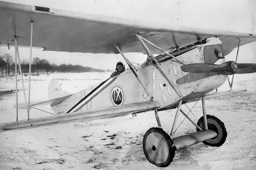
In the Pfalz under review no attempt appears to have been made to camouflage the machine, which is painted with aluminium paint all over its body and wings. The rudder tail plane and elevator are painted a dark yellow.
View attachment 634465G.141