Vought F7U Cutlass - Developments, Variants and Related Projects

Jos Heyman

ACCESS: Top Secret
Joined
15 February 2007
Messages
597
Reaction score
53
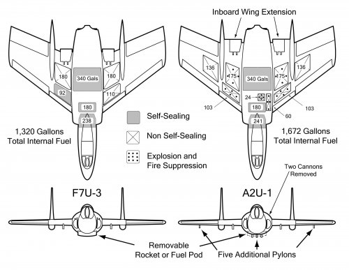
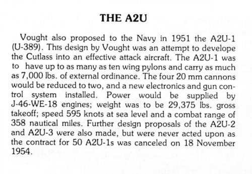
I understand that the first Vought A2U-1 (the attack version of the F7U Cutlass) was almost complete when it was cancelled on 18 November 1954.
Does anybody know what happened to the airframe (and any others that there may have been). Was it just scrapped or was it use for a F7U Cutlass, and, if so, which one?
 
All I know is BuNos were assigned -- 138372 - 138417 -- and if they almost finished one, it would certainly be BuNo 138372.

Perhaps we can check that.

;D
 
I've sent a note off to my Vought contact - will post the results....

Enjoy the Day! Mark
 
In the meantime, I've found evidence in the Vought archives that the first A2U was manufacturing complete on or about 18 October 1954, with the program being canceled a month later. In the meantime, it would have been undergoing systems checkout and/or installation of research instrumentation. (If I remember correctly, it wasn't scheduled to fly until January. The A2U was sufficiently different in detail from the F7U that it couldn't be completed as one without extensive modification.
 
The A2U was very similar externally to the F7U-3. The major external differences were the longer chord of the inboard wing panel, the additional stores stations on the belly, and the deletion of the 20mm cannon on the left side. (The stores stations on the outboard wing panel were the same as the F7U-3M.) However, there were also internal changes to systems. There will be a bit more on the airplane in my attack book, due out in July.
 

Attachments

  • A2U vs. F7U Low Res.jpg
    A2U vs. F7U Low Res.jpg
    316.7 KB · Views: 1,837
A pic from a photocopy of a Vought brochure.
 

Attachments

  • U-A2U (Vought).JPG
    U-A2U (Vought).JPG
    21 KB · Views: 1,404
these from Naval Fighters Six 'Chance Vought F7U Cutlass', page 55 :-

I was under the impression that production A2Us would have had the modified elevon. Anyone got more info?

cheers,
Robin.
 

Attachments

  • A2U - delta elevon.jpg
    A2U - delta elevon.jpg
    63.9 KB · Views: 1,377
  • A2U - data.jpg
    A2U - data.jpg
    66.1 KB · Views: 1,420
robunos said:
these from Naval Fighters Six 'Chance Vought F7U Cutlass', page 55 :-

I was under the impression that production A2Us would have had the modified elevon. Anyone got more info?

cheers,
Robin.
The A2U-1, -2, and -3 designations in the Vought brochure were not official and served only to distinguish the options. I couldn't find any stated benefit of the so-called "delta" ailevators, much less flight test results, that were part of the -2 configuration. My guess is that they increased the aspect ratio and/or the large counterbalance area reduced control loads, possibly allowing deletion of one or both of the hydraulic control systems.
 
Cool picture of the ailavator, thanks for sharing! I had never seen something like that, it's like a relative of the isoclinic wing.
I'd be interested too in finding out the relative advantages.
I can only think of increased effectiveness at high angle of attack, which would have obviously been beneficial on landing for the Cutlass.
 
I'd be somewhat concerned about flutter/stiffness issues with the balance area on the ailavator, especially at large deflection angles...

let me get this right, then, there were three different options outlined by Vought for the A2U, identified by them as A2U-1, A2U-2, and A2U-3, and each having differing degrees of modification, compared to the baseline F7U-3

cheers,
Robin.
 
robunos said:
I'd be somewhat concerned about flutter/stiffness issues with the balance area on the ailavator, especially at large deflection angles...

let me get this right, then, there were three different options outlined by Vought for the A2U, identified by them as A2U-1, A2U-2, and A2U-3, and each having differing degrees of modification, compared to the baseline F7U-3

cheers,
Robin.
From my attack book, to be published in July:
"Because Westinghouse had not been able to increase the J46’s thrust and reduce its fuel consumption as expected, the F7U-3 was short on range. Nevertheless, the Cutlass was well regarded for its air-to-ground capability and was among the first to drop a bomb while supersonic. Vought was promoting an attack variant, the V-389, as early as 1951 and trying to get the Marines interested in a shore-based version as well. Vought provided a brochure-type proposal to the Navy in 1952 that provided a shopping list of improvements to the F7U-3 as an attack aircraft. In order to carry additional stores, it suggested adding a small pylon on the inboard wing just outboard of the existing high capacity pylon and three small pylons on each outboard wing panel. The “A2U-1” was powered by two J46-WE-8 engines. The inboard wing was extended aft along with the speed brakes to provide more wing area. The “A2U-2” had a more significant change to the wing—the fins were moved inboard by about six inches and the outer wing panel had less chord and big “delta” ailevators that together increased the aspect ratio of the wing—and was to be powered by two J46-WE-2s. The “A2U-3” was the “-2” reengined with either two afterburning Wright J65s, a license-built derivative of the Bristol-Siddeley Sapphire, or two J47-GE-2s instead of the perennially troubled Westinghouse J46s."
 
"Because Westinghouse had not been able to increase the J46’s thrust and reduce its fuel consumption as expected, the F7U-3 was short on range. Nevertheless, the Cutlass was well regarded for its air-to-ground capability and was among the first to drop a bomb while supersonic. Vought was promoting an attack variant, the V-389, as early as 1951 and trying to get the Marines interested in a shore-based version as well. Vought provided a brochure-type proposal to the Navy in 1952 that provided a shopping list of improvements to the F7U-3 as an attack aircraft. In order to carry additional stores, it suggested adding a small pylon on the inboard wing just outboard of the existing high capacity pylon and three small pylons on each outboard wing panel. The “A2U-1” was powered by two J46-WE-8 engines. The inboard wing was extended aft along with the speed brakes to provide more wing area. The “A2U-2” had a more significant change to the wing—the fins were moved inboard by about six inches and the outer wing panel had less chord and big “delta” ailevators that together increased the aspect ratio of the wing—and was to be powered by two J46-WE-2s. The “A2U-3” was the “-2” reengined with either two afterburning Wright J65s, a license-built derivative of the Bristol-Siddeley Sapphire, or two J47-GE-2s instead of the perennially troubled Westinghouse J46s."

Many thanks indeed!! :D

looking forward to your next book, shaping up to be a worthy companion to your Fighters book, shelf space already allocated! ;D

cheers,
Robin.
 
Here is an interesting Vought design.
From Vought Archives

V-366H Design Study
 

Attachments

  • CVS-22322_V-366H_Design_Study_Inv.jpg
    CVS-22322_V-366H_Design_Study_Inv.jpg
    53.9 KB · Views: 2,585
Here is a little larger.
 

Attachments

  • CVS-22322_V-366H_Design_Study.jpg
    CVS-22322_V-366H_Design_Study.jpg
    207.2 KB · Views: 1,099
My usual cleanup attempt :) Free cleanup service provided for any authors who want it....
 

Attachments

  • V-366H.jpg
    V-366H.jpg
    187.1 KB · Views: 1,198
Orionblamblam said:
Huh. That's all kinds of Heinkely awesome. [...]
Yeh, inspired by the Heinkel P.1078B. But the nose wheel is central and attached on the main fuselage.
Cockpit, guns, unguided rockets, engine inlet, radar etc. are in 2 seperate gondolas, because they all need the frontal area. It is a way of keeping the front fuselage diameter small.
That early Lockheed UCAV design had a similar starting-point.
 
A good way to allow the pilot a good view over the nose.

I wonder why the guns werent mounted under the intake. Surely a centerline position is better than off axis?
 
overscan said:
My usual cleanup attempt :) Free cleanup service provided for any authors who want it....

Thanks. What program do you use?
 
A very interesting project! Even the "normal" Cutlass is unusual enough, but a twin-fuselage Cutlass...
 
Bill S said:
overscan said:
My usual cleanup attempt :) Free cleanup service provided for any authors who want it....

Thanks. What program do you use?

GIMP, which is a free open source program. But you can do the same with any photo-editing package.
 
I wonder how the pilot feels about having a radar emitting so close to his groin... Better hope that antenna has no side lobes...
 
overscan said:
Bill S said:
overscan said:
My usual cleanup attempt :) Free cleanup service provided for any authors who want it....

Thanks. What program do you use?

GIMP, which is a free open source program. But you can do the same with any photo-editing package.

...A simple Auto-Contrast in Photoshop does wonders just by itself on most blueprint scans. For really dirty scans, tweaking using Contrast and Brightness takes care of about 90% of the rest, while the remaining 10% can be handled with a simple Brush tool.

[thinks]

...Frack me. Has it *really* been 14 years since the first time I cleaned up scanned blueprints way back at Summagraphics???
 
fightingirish said:
Yeh, inspired by the Heinkel P.1078B.
;D Very interesting and unusual, thanks. IIRC, less than 10 projects featured this layout of single-fuselage twin-nose (the most famous being the Twin-Harrier I think).
 
...A simple Auto-Contrast in Photoshop does wonders just by itself on most blueprint scans. For really dirty scans, tweaking using Contrast and Brightness takes care of about 90% of the rest, while the remaining 10% can be handled with a simple Brush tool.

[thinks]

...Frack me. Has it *really* been 14 years since the first time I cleaned up scanned blueprints way back at Summagraphics???

Thanks for the tip. I typically concentrate more on getting the scan and have not experimented that much with functions in ps.
I have noticed that nearly every time I post, someone feels compelled to clean up my scans. As a result, I am trying to learn what it is that I am doing wrong. Thanks for the information!
 
I wouldn't worry about it Bill. I typically will save a raw scan exactly as the scanner provided it, kind of like a "negative", then I will try to clean it up and save that as a separate file. The cleanup process can lose details, and there is always the possibility that in the future I or someone else will find a better cleanup method, but once you've edited the file you can't get back the details you have removed. So its good to have the original scan as well as the cleaned up one.
 
"Surely a centerline position is better than off axis"

due to the central intake,this could have meant ingestion of the gun gases,
which for eyample was a problem for the early Hawker Hunter.
 
Bill S said:
I have noticed that nearly every time I post, someone feels compelled to clean up my scans. As a result, I am trying to learn what it is that I am doing wrong.

The only valid arguement that can be made that you are doing something wrong is that you are not posting *enough.* As for people cleaning up your scans... well, it's something that a number of us can do fairly easily, and it turns into something of a hobby.
 
Jemiba said:
"Surely a centerline position is better than off axis"

due to the central intake,this could have meant ingestion of the gun gases,
which for eyample was a problem for the early Hawker Hunter.
Surely to be mounted on the center line they would have to be behind the intake.
But talking of ingestion how would the engines feel about ingesting a volley of rocket exhaust?
 
Just as a reference, the afore-mentioned Heinkel He P.1078 . . . .
 

Attachments

  • Heinkel P.1078-4 B.png
    Heinkel P.1078-4 B.png
    88.7 KB · Views: 1,067
I had no idea that the Heinkel P.1078B had any serious conceptual merit, nor that its concepts had been examined after the war
 
I rather think the Heinkel 1078 is quite an elegant solution. If you wish to rapidly build an airframe then tailless makes sense. However you need yaw stability and the bell shaped lift distribution used by the Hortens is [some might say] dubious. This type of wing gives you the effective fin area and all from one component, made in one jig. Further proof of the merit of this layout is its subsequent adoption for the Boeing 'Bird of Prey'.

S
 
Surely a point that also must be considered is that where the cockpit is positioned off centre or too far away from the centre of pressure/lift, the G forces on the pilot would be magnified in any high G manouvres.
 
malcolm said:
Surely a point that also must be considered is that where the cockpit is positioned off centre or too far away from the centre of pressure/lift, the G forces on the pilot would be magnified in any high G manouvres.

No, actually they wouldn't. The majority of G-Loading happens in pitch and as such, if the aircraft is pulling 9-gs, it's 9-gs everywhere. Now, in rolling maneuvers, he would feel a little heavier in the pants, very slight increase in g's, when rolling right, and slightly less when rolling left. However, they don't pull much in the way of "rolling G's" because they are so close to the center of rotation.

At the very least, it wouldn't be much worse than it is in a Sea Vixen, an A-6, or any other combat aircraft with side by side seating.
 

Similar threads

Back
Top Bottom