Should we attach high resolution images from the NASA web sites or should we hotlink them?

You are using an out of date browser. It may not display this or other websites correctly.
You should upgrade or use an alternative browser.
You should upgrade or use an alternative browser.
Vought F7U Cutlass - Developments, Variants and Related Projects
- Thread starter Jos Heyman
- Start date
- Joined
- 27 December 2005
- Messages
- 18,718
- Reaction score
- 33,084
Attach them, subject to guidelines here:
http://www.secretprojects.co.uk/forum/index.php/topic,11055
http://www.secretprojects.co.uk/forum/index.php/topic,11055
- Joined
- 27 December 2005
- Messages
- 18,718
- Reaction score
- 33,084
- Joined
- 13 June 2007
- Messages
- 2,220
- Reaction score
- 3,541
Greetings All -
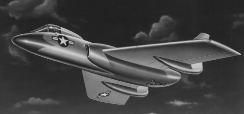
In the Vought Archives was a study dated April 27, 1951 looking at single engine options for the pair of Westinghouse J46 engines in the production version of the F7U-3. As I recall, no other aircraft used the J-46 and with Westinghouse's recent track record for the J-40, and an apparent lack of interest in developing the J-46 further, it makes sense that single engine options were being looked at. I've always liked the Cutlass and felt that it was hampered by its engines. Tailspin Turtle noted previously that it was also hampered by the straight deck in use at the time - the angled deck would have significantly improved its safety record out on the boat.
I've forwarded to PMM the full report as a PDF and hope it can posted in its entirety.
Enjoy the Day! Mark
Attachments
-
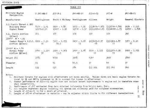 xF7U-3 Engine Data.jpg273.7 KB · Views: 1,162
 -
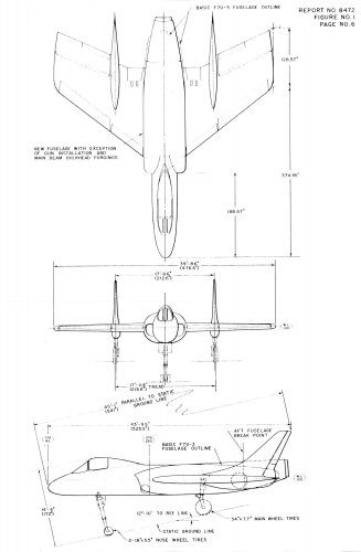 xF7U-3 Fuselage Outline Single Engine.jpg161.7 KB · Views: 1,197
 -
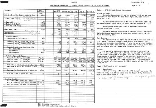 xF7U-3 Single Engine Performance Comparison.jpg467.1 KB · Views: 1,122
 -
 xF7U-3 P&W J-57-P-1 Installation.jpg222.2 KB · Views: 1,023
 -
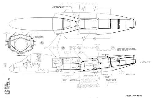 xF7U-3 Westinghouse J40-WE-10 Installation.jpg216.6 KB · Views: 755
 -
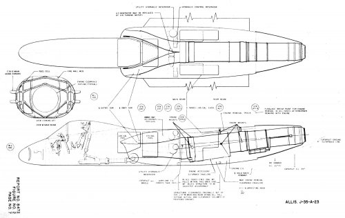 xF7U-3 Allison J-35-A-23 Installation.jpg225 KB · Views: 445
 -
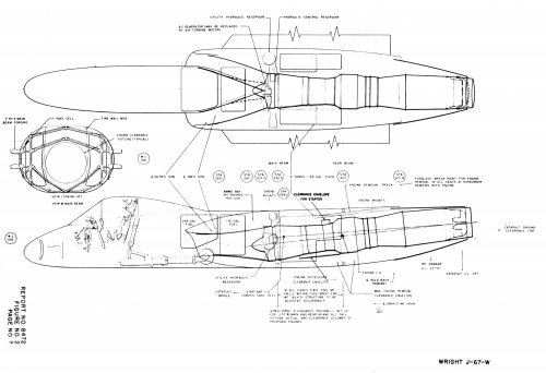 xF7U-3 Wright J-67-W Installation.jpg235.2 KB · Views: 442
 -
 xF7U-3 GE J47-GE-21 Installation.jpg240.6 KB · Views: 538
- Joined
- 27 December 2005
- Messages
- 18,718
- Reaction score
- 33,084
- Joined
- 17 October 2006
- Messages
- 2,396
- Reaction score
- 1,278
Awesome. Way to make the Gutless even more dangerous.
LowObservable said:Awesome. Way to make the Gutless even more dangerous.
Not necessarily...some of these engines seem to have offered more thrust for the weight, which by all accounts the Cutlass could have used. And that doesn't account for the cascading weight reduction in moving to a single engine, not huge but significant. Almost everything engine-related that that the Cutlass had two of, right down to the cockpit gauges and throttles, would be cut in half. It's not like the Cutlass was likely much better off on just one of its two original engines.
- Joined
- 13 June 2007
- Messages
- 2,220
- Reaction score
- 3,541
There's a number of first hand accounts from pilots about the Cutlass that were quite complimentary of its flying characteristics. The negative monikers for the Cutlass came more from its history around the back of the boat and problems with the engines (and lack of oomph from them) and some of its complexity which I think is more a reflection of how aircraft as a whole were evolving. I'd love to see the Pax River reports to see what was said in the evaluations. A J-57 powered Cutlass would have been impressive.
Enjoy the Day! Mark
Enjoy the Day! Mark
- Joined
- 19 February 2007
- Messages
- 1,600
- Reaction score
- 3,281
They tried that.Mark Nankivil said:A J-57 powered Cutlass would have been impressive.
Marketing forced them to change the name from "Cutlass" to "Crusader".

- Joined
- 17 May 2008
- Messages
- 702
- Reaction score
- 1,653
While looking for a place to put a drawing of the V-346 with droppable wing tanks, in searching I found this post.
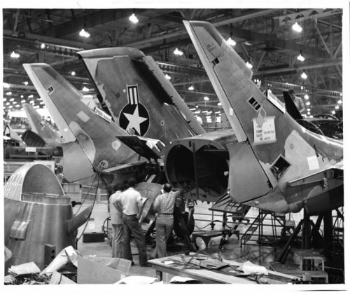
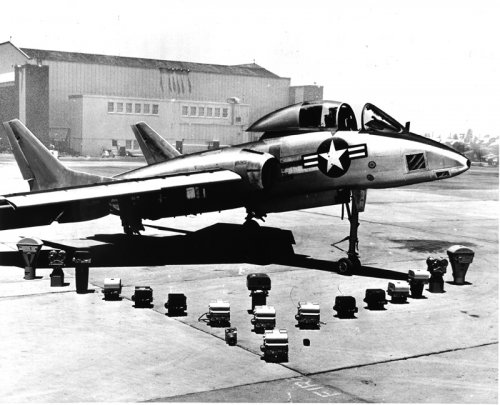
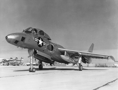
Here is a production line photo of A2U-1 with a 10-8-54 completion date on the vertical.
Vought Aircraft Historical Foundation photo credit.
bill
Here is a production line photo of A2U-1 with a 10-8-54 completion date on the vertical.
Vought Aircraft Historical Foundation photo credit.
bill
Attachments
- Joined
- 17 May 2008
- Messages
- 702
- Reaction score
- 1,653
Thanks for combining the different but related topics.
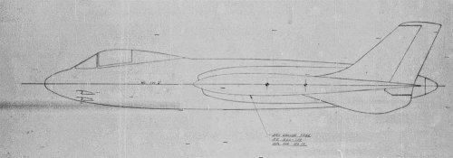
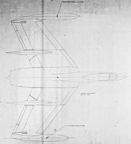
Here are a couple views of the V-346 with 250 gallon dropable wing tanks
This came from a very dark microfilm and is a very poor image, but the best I could obtain.
Vought Aircraft Heritage Foundation
bill
Here are a couple views of the V-346 with 250 gallon dropable wing tanks
This came from a very dark microfilm and is a very poor image, but the best I could obtain.
Vought Aircraft Heritage Foundation
bill
Attachments
- Joined
- 17 May 2008
- Messages
- 702
- Reaction score
- 1,653
Mark previously posted the study of looking at engine options in 1951.
I recently found drawings of the same type study done in 1946 on the V-346.
Here are the Rolls Royce RB41 Nene and a pair of Rolls Royce RB37 Derwent VI engines
Vought Aircraft Heritage Foundation
bill
I recently found drawings of the same type study done in 1946 on the V-346.
Here are the Rolls Royce RB41 Nene and a pair of Rolls Royce RB37 Derwent VI engines
Vought Aircraft Heritage Foundation
bill
Attachments
-
 CVS-15470-V-346A-Gen-Arr-Rolls-Royce-RB41-Nene-TopView.jpg98.2 KB · Views: 1,154
 -
 CVS-15470-V-346A-Gen-Arr-Rolls-Royce-RB41-Nene-SideView.jpg55.5 KB · Views: 1,122
 -
 CVS-15474-V-346A-Gen-Arr-Derwent-VI-TopView.jpg59.3 KB · Views: 494
 -
 CVS-15474-V-346A-Gen-Arr-Derwent-VI-SideView.jpg49.1 KB · Views: 519
- Joined
- 17 May 2008
- Messages
- 702
- Reaction score
- 1,653
Tommy Wrote:
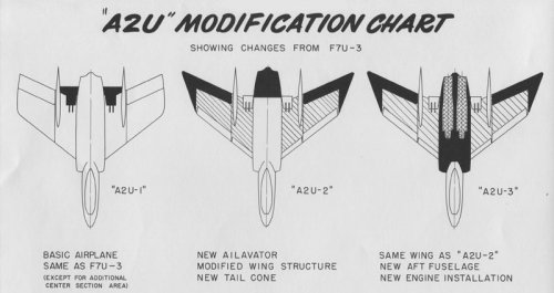
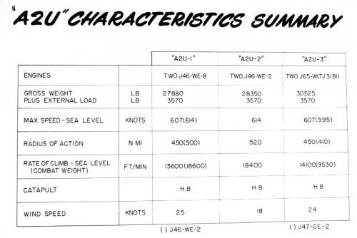
"The A2U-1, -2, and -3 designations in the Vought brochure were not official and served only to distinguish the options. I couldn't find any stated benefit of the so-called "delta" ailevators, much less flight test results, that were part of the -2 configuration. My guess is that they increased the aspect ratio and/or the large counterbalance area reduced control loads, possibly allowing deletion of one or both of the hydraulic control systems."
From Vought Report 8690, here is a drawing to illustrate the A2U-1, -2, -3 showing differences in Ailavators, wing structure and engines that Tommy discussed in post #8 of this subject.
bill
Attachments
- Joined
- 17 May 2008
- Messages
- 702
- Reaction score
- 1,653
- Joined
- 13 June 2007
- Messages
- 2,220
- Reaction score
- 3,541
Nice finds Bill - thanks! Mark
- Joined
- 17 May 2008
- Messages
- 702
- Reaction score
- 1,653
Here is a combination photo and drawing of the F7U-3P.
The eventual aircraft had a different nose profile.
The second photo reveals the optical view finder underneath
the nose forward of the nose gear door and aft of the vertical
camera windows.
The eventual aircraft had a different nose profile.
The second photo reveals the optical view finder underneath
the nose forward of the nose gear door and aft of the vertical
camera windows.
Attachments
- Joined
- 17 May 2008
- Messages
- 702
- Reaction score
- 1,653
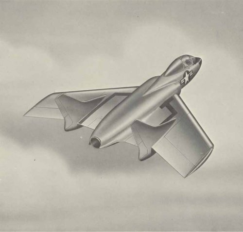
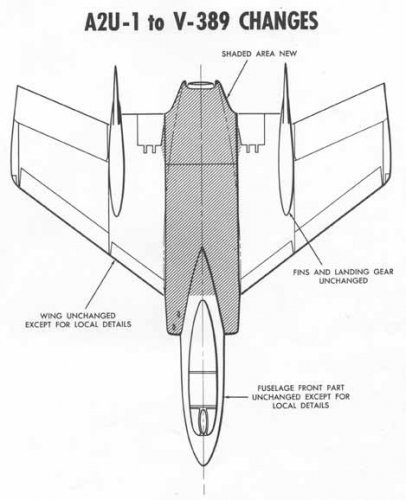
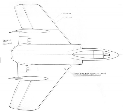
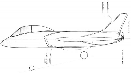
A January 1954 Chance Vought V-389 proposal was for an improved performance
attack aircraft based upon the A2U-1 Cutlass. The proposal featured a single Pratt and
Whitney J57-P-4 engine replacing the twin Westinghouse J46 engines. A new fuselage
section from the inlets aft would be required to house the single engine. The V-389
would share major components of the A2U-1 including wings, vertical tails, landing
gear and forward fuselage.
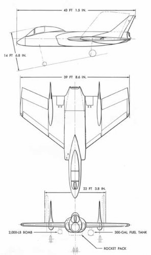
The powerplant change caused a significant increase in radius of action, 280 nautical
miles for a total radius of 605 NM while using only internal fuel and carrying two 2,000lb
bombs. The V-389 equipped with external fuel and a “special weapon*” had a radius of 815 NM.
AIRPLANE V-389 A2U-1
ENGINE J57-P-4 TWO J46-WE-18
Loading Two 2,000 lb Bombs 3,500 lb Store, 300 Gallon Drop Tank and 220 Gallon Fuel Pack Two 2,000 lb Bombs 3,500 lb Store, 300 Gallon Drop Tank and 220 Gallon Fuel Pack
Gross Weight 34,830 lbs. 38,170 lbs. 33,950 lbs. 37,330 lbs.
Combat Radius (NM) 605 815 325 500
Max Speed, Sea Level
Clean Configuration (kts) 598 598 593 593
There appeared to be little official interest in the proposal and eventually the entire A2U-1 program was canceled. The V-389 is left as another interesting “what if”.
*The F7U-3 was cleared in separation tests to carry the Mk 7, 8, 11, and 12 stores.
attack aircraft based upon the A2U-1 Cutlass. The proposal featured a single Pratt and
Whitney J57-P-4 engine replacing the twin Westinghouse J46 engines. A new fuselage
section from the inlets aft would be required to house the single engine. The V-389
would share major components of the A2U-1 including wings, vertical tails, landing
gear and forward fuselage.
The powerplant change caused a significant increase in radius of action, 280 nautical
miles for a total radius of 605 NM while using only internal fuel and carrying two 2,000lb
bombs. The V-389 equipped with external fuel and a “special weapon*” had a radius of 815 NM.
AIRPLANE V-389 A2U-1
ENGINE J57-P-4 TWO J46-WE-18
Loading Two 2,000 lb Bombs 3,500 lb Store, 300 Gallon Drop Tank and 220 Gallon Fuel Pack Two 2,000 lb Bombs 3,500 lb Store, 300 Gallon Drop Tank and 220 Gallon Fuel Pack
Gross Weight 34,830 lbs. 38,170 lbs. 33,950 lbs. 37,330 lbs.
Combat Radius (NM) 605 815 325 500
Max Speed, Sea Level
Clean Configuration (kts) 598 598 593 593
There appeared to be little official interest in the proposal and eventually the entire A2U-1 program was canceled. The V-389 is left as another interesting “what if”.
*The F7U-3 was cleared in separation tests to carry the Mk 7, 8, 11, and 12 stores.
Attachments
- Joined
- 3 June 2006
- Messages
- 3,406
- Reaction score
- 5,620
Link: http://voughtworks.blogspot.com/2016/07/v-389-more-details.htmlBill Spidle said:V-389 More Details
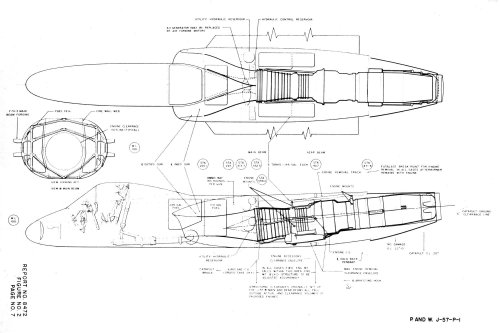
Continuing with V-389 information is a look at the actual J57-P-4 engine installation into the A2U-1 airframe. This installation drawing shows the placement of the engine and afterburner assembly into the A2U fuselage. Basically aft of fuselage station 265.1 a structural production break the fuselage is new. One major internal change is the changing from a central shear panel (formerly between the two engines) to two shear panels (one on either side of the engine) to absorb fuselage bending loads and fuel inertial loads. All the changes to the fuselage still enable the same wing root rib to be used with the slight exception at the tail cone. [...]
- Joined
- 17 May 2008
- Messages
- 702
- Reaction score
- 1,653
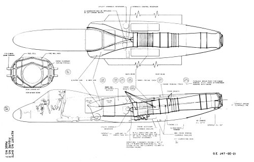
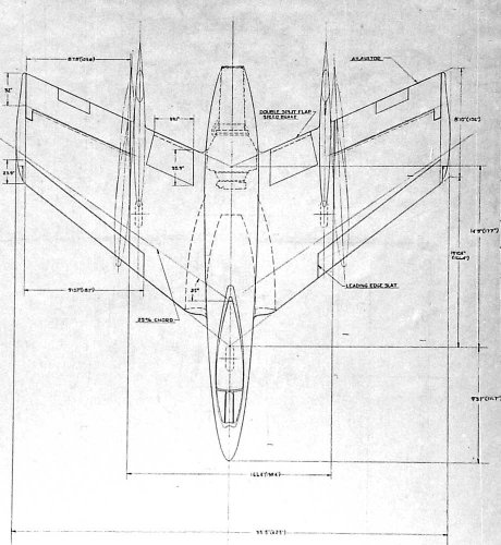
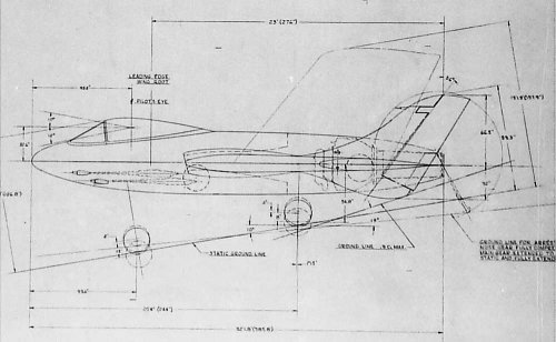
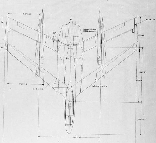
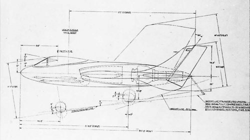
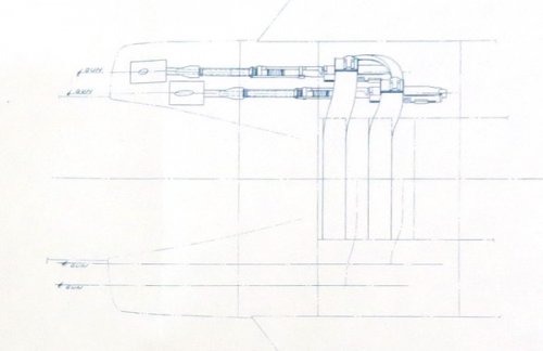
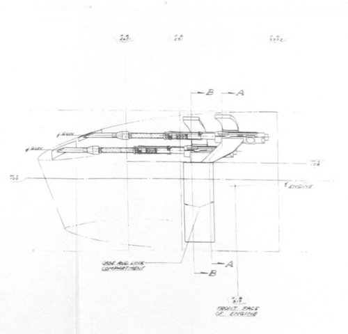
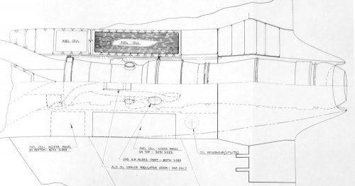
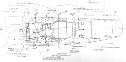
Continuing with V-389 information is a look at the actual J57-P-4 engine installation into the A2U-1 airframe.
The installation drawing shows the placement of the engine and afterburner assembly into the A2U fuselage.
Basically aft of fuselage station 265.1 a structural production break the fuselage is new. One major internal
change is the changing from a central shear panel (formerly between the two engines) to two shear panels (one
on either side of the engine) to absorb fuselage bending loads and fuel inertial loads.
All the changes to the fuselage still enable the same wing root rib to be used with the slight exception at the
tail cone. Changes to the wing center section was fairly mild. The center-section pylons are moved 9.7 inches aft
of the A2U location. The pylons attached to the main wing beam and aft beam instead of the front beam and main
beam. In addition to the pylons the aft end of the wing root was to be changed to adapt to the new aft fuselage
cone for the single exhaust. Under the skin lighter electrical and hydraulic systems were incorporated. The electrical
system would incorporate a separate AC and DC circuits with AC generation taking place by a bleed air turbine
generator. Weight would be saved by removing one DC generator, internal battery, and two inverters.
The hydraulic system incorporated an emergency ram-air-turbine driven hydraulic pump and alternator.
The utility system reservoir was redesigned to accommodate the lower fluid volume requirements. One utility system
pump was eliminated due to a new higher efficiency pump and the hydraulic oil cooler was eliminated.
Another subtle change was the installation of only two MK12 guns above the right-hand inlet duct with provisions
for a second set over the left-hand inlet duct. The gun muzzles are staggered and located aft of the duct lip instead
of in the air duct lip like the A2U-1.
Source Chance Vought Engineering Report 8847 V-389 Attack Airplane Design Report, NARA II
Attachments
-
 MK12-Plan-View-V-389.jpg42.3 KB · Views: 392
 -
 MK12-Profile-View-V-389.jpg48.5 KB · Views: 782
 -
 V-389-and-A2U-lines-differences-Plan-View.jpg87.9 KB · Views: 802
 -
 V-389-and-A2U-lines-differences-Profile-View.jpg61.9 KB · Views: 810
 -
 V-389-J57-Plan-View.jpg110.5 KB · Views: 806
 -
 V-389-J57-Profile-View.jpg116.5 KB · Views: 873
blackkite
Don't laugh, don't cry, don't even curse, but.....
- Joined
- 31 May 2007
- Messages
- 9,409
- Reaction score
- 9,272
Hi!
http://blog.livedoor.jp/janome_gotyou/archives/cat_136375.html
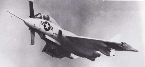
"This F7U-3 (Bu.No. 129566), equipped with a bar with sensors belonged mixed test squadron VC-3. At one stage of testing before and behind the cockpit were two vertical aerodynamic surfaces are then dismantled."
http://blog.livedoor.jp/janome_gotyou/archives/cat_136375.html
"This F7U-3 (Bu.No. 129566), equipped with a bar with sensors belonged mixed test squadron VC-3. At one stage of testing before and behind the cockpit were two vertical aerodynamic surfaces are then dismantled."
Attachments
blackkite said:Hi!
"This F7U-3 (Bu.No. 129566), equipped with a bar with sensors belonged mixed test squadron VC-3. At one stage of testing before and behind the cockpit were two vertical aerodynamic surfaces are then dismantled."
After its brief service career, this F7U-3 was bailed to Cornell Aeronautical Laboratory for inflight research. I can't find anything about this specific project on line but I may have a test report in storage.
Grey Havoc
ACCESS: USAP
- Joined
- 9 October 2009
- Messages
- 24,413
- Reaction score
- 17,872
The F7U-3 was qualified to deliver nuclear weapons and deployed with several VF and VA squadrons. In parallel with the A4D program, the Navy contracted with Vought for an attack derivative of the Cutlass, the A2U.

However, the A2U-1 was cancelled based on the development problems with the Westinghouse J46 engine and the availability of another, less expensive option from North American, the FJ-4B.

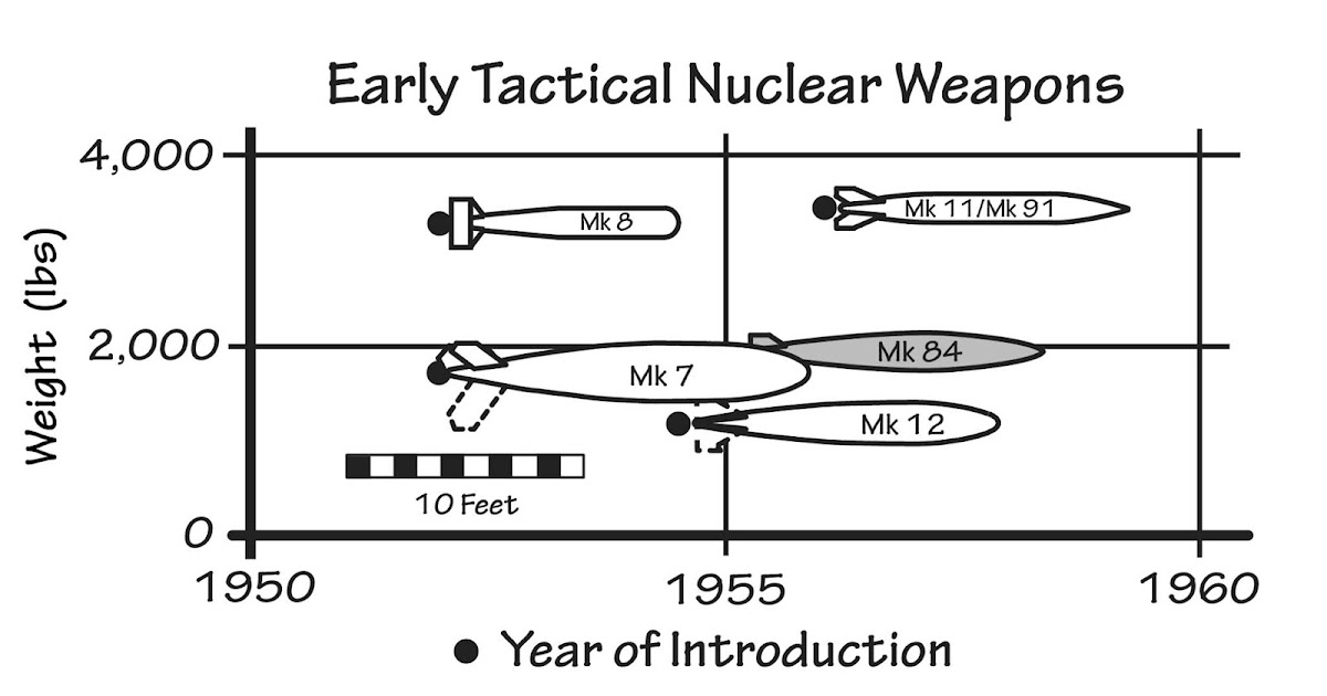
U.S. Navy 1950s Light-Attack Jet Programs
By January 1952, nuclear weapons light enough to be carried by tactical fighters and bombers had been qualified and were being stockpiled. ...
 thanlont.blogspot.com
- Joined
- 17 May 2008
- Messages
- 702
- Reaction score
- 1,653
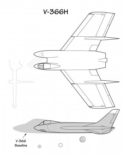
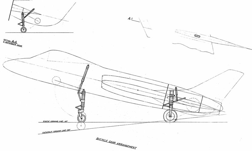
Additional design study work was requested by the BuAer for the F7U development program. The V-366A/B/C had listed "undesirable catapult take-off characteristics, unprotected fuel tanks, insufficient vision over the nose and insufficient strength to meet current Bureau strength requirements." The V-366, (improved F7U-1) with Westinghouse 24C jet engines (J46) and improved radar, armament combination.
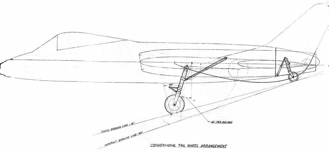
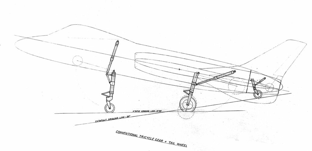
The BuAer requested the contractor to study landing gear arrangements other than the conventional tricycle gear for application in the design. It was an attempt at solutions to the "problems associated with operating a swept wing airplane off an aircraft carrier."
The BuAer requested the contractor to study landing gear arrangements other than the conventional tricycle gear for application in the design. It was an attempt at solutions to the "problems associated with operating a swept wing airplane off an aircraft carrier."
- The conventional tail wheel was "not satisfactory due to high bearing loads in the strut and the adverse effect on airplane balance."
- Tricycle gear with addition of a small tail wheel was evaluated next. This arrangement allowed the airplane to rock back on the tail wheel as the bridle and holdback are tensioned. The catapult bridle was planned to maintain the airplane on the main and tail wheel after the catapult was fired. This study with others led to a better solution of an extensible nose wheel strut removing dependency on the catapult bridle maintaining take-off attitude.
- The third arrangement was a bicycle arrangement which was more difficult to implement due to fuselage space arrangements and weight. The fuselage would need reinforcement for the landing gear loads, the out riggers had to be heavy due to barrier crash loads.
- In the end it was concluded that none of the configurations considered offered improvement over the conventional tricycle landing gear of the V-366 proposal
Attachments
I can't wait for Al's Cutlass book so that we can put these misconceptions behind us. It would appear that an advanced design plus entrenched attitudes were the main issue, not the aircraft.As if the Cutlass wasn't enough of a pilot killer - yeah guys, let's put a tailwheel to make it worse !
- Joined
- 5 May 2007
- Messages
- 368
- Reaction score
- 495
Some remarkable flight test and carrier landing footage of the Vought F7U Cutlass posted at the Texas Archive of the Moving Image. (H/T to "War Zone" poster 1127fctwosw who posted links to that footage this morning [26-April-2023] in the comments section - link).
The cockpit footage, from the battering the test pilot takes inside, to his (eventually successful) attempts to eject is nightmare fuel.
I am hoping my attempts to embed the footage works, but if not, please go to the hyperlinked titles to view it. The descriptions below the hyperlinked titles are those posted with the footage by the Texas Archive of the Moving Image.
Texas Archive of the Moving Image - Chance Vought Aircraft - Spin Maneuver and Subsequent Ejection (1954)
With a camera set to record his reactions, John McGuyrt, chief test pilot for Chance Vought Aircraft stalled an F7U-3, putting it into a deliberate spin, from which he was unable to recover. This film documents his harrowing experience as he struggles to escape from the cockpit. With just seconds remaining before the plane crashed into the ground, McGuyrt was able to bail out, parachuting to safety. The aircraft was destroyed, but the camera, still intact, was found among the wreckage. Chance Vought Aircraft circulated the film to scientists and engineers in the promotion of flight safety.
<iframe width="485" height="385" src="https://texasarchive.org/glifosrichmedia/build?id=2011_02421_480x360&embed" frameborder="0">
Texas Archive of the Moving Image - Stresses Affecting the Pilot During Post Stall Maneuvers in High Performance Aircraft (1954)
Part of a series of tests performed on the Vought F7U line of fighter planes, this footage records the effects of variable post-stall conditions on a Chance Vought's chief test pilot, John McGuyrt. The final clip records his harrowing experience when the plane goes into a spin from which he cannot recover. With just seconds remaining before the plane crashed into the ground, McGuyrt was able to bail out, parachuting to safety. The aircraft was destroyed, but the camera, still intact, was found among the wreckage. Chance Vought Aircraft circulated the film to scientists and engineers in the promotion of flight safety.
<iframe width="485" height="385" src="https://texasarchive.org/glifosrichmedia/build?id=2011_02418_480x360&embed" frameborder="0">
Texas Archive of the Moving Image - Vought F7U-3 Aircraft Carrier Crash Landings
This footage documents the Vought F7U-3 Cutlass in a series of unsuccessful aircraft carrier landings. One particularly unnerving landing captures an inadvertent seat ejection in which the pilot, possibly F.C. Turner, likely suffered a back injury.
<iframe width="485" height="385" src="https://texasarchive.org/glifosrichmedia/build?id=2011_02417_480x360&embed" frameborder="0">
southwestforests
ACCESS: Top Secret
- Joined
- 28 June 2012
- Messages
- 984
- Reaction score
- 1,904
It was necessary to use the links.I am hoping my attempts to embed the footage works, but if not, please go to the hyperlinked titles to view it.
Those are indeed some stress-inducing spots to be in.
Quite interesting how canopy detached and went flying ahead in those landing films.
martinbayer
ACCESS: Top Secret
- Joined
- 6 January 2009
- Messages
- 4,735
- Reaction score
- 6,486
Jeez, for a moment there I was truly creeped out - I thought some Autonomous Intelligence doohickey was going to take a crack at generating an F7U type history...I can't wait for Al's Cutlass book so that we can put these misconceptions behind us. It would appear that an advanced design plus entrenched attitudes were the main issue, not the aircraft.As if the Cutlass wasn't enough of a pilot killer - yeah guys, let's put a tailwheel to make it worse !
- Joined
- 11 March 2011
- Messages
- 322
- Reaction score
- 1,326
In process of carving this, and darn if I can recall where I found the 3 views..... love to find more data and wonder if there is anyone out there with more details? The little hump on the back was to be a rear canopy for the GIB and a big ass cruise missile was the load....


Last edited:
southwestforests
ACCESS: Top Secret
- Joined
- 28 June 2012
- Messages
- 984
- Reaction score
- 1,904
Ohh, move the propellor pods out a bit and model it in stick and tissue rubber band power.In process of carving this, and darn if I can recall where I found the 3 views.....
If the design was offered in a nice plastic kit as is I would buy and build it - as long as it had the pilot guy, no guy, no sale.
- Joined
- 17 May 2008
- Messages
- 702
- Reaction score
- 1,653
It was one of the design iterations of the V-356 VA Airplane. Two PT-2 "Prop Turbines" The bubble on the back is listed as the Radio Operator cockpit. The payload was a 4,000lb missile in the 150" long internal bay. It also had two launching tubes for 20-5" fin stabilized rockets.In process of carving this, and darn if I can recall where I found the 3 views..... love to find more data and wonder if there is anyone out there with more details? The little hump on the back was to be a rear canopy for the GIB and a big ass cruise missile was the load....
View attachment 698638
EDIT: 10' - 0" diameter counter rotating props, unknown number of blades. 49' - 0" wing span. 46' - 0" tip of nose to upper aft tip of rudder. Another unusual dimension on the drawing is 70" between the rocket tube centerlines. Engines are canted down 3 degrees at the front. The drawing I have is horrible and all this information was extracted with great difficulty.
EDIT2: This actually belongs here: https://www.secretprojects.co.uk/threads/us-navy-outline-specification-os-112.9866/#post-211851
Last edited:
Blue Angel Pilot interview covering the short time they flew a couple of Cutlass.
View: https://youtu.be/Fwyk18aow70
nearly 600 degree per second... With Dutch roll offsetting the nose like crazy!
Last edited:
- Joined
- 11 March 2011
- Messages
- 322
- Reaction score
- 1,326
Updated, and in 1/24th. Made it sans the stupid rear canopy idea... they would have tossed it for sure. And yes, to those who are astute...it is the stand for the Tandem that I will post separately.


Scott Kenny
ACCESS: USAP
- Joined
- 15 May 2023
- Messages
- 16,977
- Reaction score
- 24,085
Not any worse than they feel about ingesting gunsmoke. Turn the ignitors on for that, else you will flame out.Surely to be mounted on the center line they would have to be behind the intake.
But talking of ingestion how would the engines feel about ingesting a volley of rocket exhaust?
(combined response)There's a number of first hand accounts from pilots about the Cutlass that were quite complimentary of its flying characteristics. The negative monikers for the Cutlass came more from its history around the back of the boat and problems with the engines (and lack of oomph from them) and some of its complexity which I think is more a reflection of how aircraft as a whole were evolving. I'd love to see the Pax River reports to see what was said in the evaluations. A J-57 powered Cutlass would have been impressive.
Enjoy the Day! Mark
Bumped into a guy on FB a while back that claimed to have a flying F7U. He said that the problem was how the exhaust nozzle worked on the J46. Seems the engine spins at full RPM, and thrust is varied by nozzle constriction (weird, and first I'd heard of such a control scheme). Open the nozzle too quickly and the combustion chambers blow out. No thrust, when you need it the most!I can't wait for Al's Cutlass book so that we can put these misconceptions behind us. It would appear that an advanced design plus entrenched attitudes were the main issue, not the aircraft.
southwestforests
ACCESS: Top Secret
- Joined
- 28 June 2012
- Messages
- 984
- Reaction score
- 1,904
Open the nozzle too quickly and the combustion chambers blow out. No thrust, when you need it the most!
though it goes without saying, I'm going to go and say that thing, That would be an issue in combat engagements. And maybe even a greater issue in bolters.
Similar threads
-

-
General Dynamics and Vought Navalised F-16s to VFAX/NACF requirement
- Started by Mark Nankivil
- Replies: 86
-
-

-