Various Focke-Wulf projects

Do you mean something like this Hesham? ??? From Justo's work/files posted on another thread and my SB render :)
 

Attachments

  • Screenshot_2016-09-19-15-43-50.png
    Screenshot_2016-09-19-15-43-50.png
    191.1 KB · Views: 327
  • Fw.jpg
    Fw.jpg
    188 KB · Views: 371
Imperialist said:
Do you mean something like this Hesham? ??? From Justo's work/files posted on another thread and my SB render :)

Yes it's,thank you Imperialist.
 
The Focke-Wulf Ta-183 "Huckebein" design team was lead by the respected and accomplished German aerospace engineer Kurt Tank, who lended his surname's first two digits to some of his ambitious late-war designs, such as this one, the Ta-152 fighter-interceptor, and the Ta-400 strategic bomber design which was a contender in the "Amerika bomber" program. The Ta-183 had completed windtunnel testing using a scale replica of the Ta-183 design, and it's aerodynamic and drag characteristics were then used to calculate the aircraft's performance. The resulting aircraft would have had a top speed of 960 km/h, a climb-rate of 20,4 m/s, and a service ceiling of 14,400m. The Ta-183 was scheduled to have it's first flight in either May or June of 1945 powered by a Jumo 004b, but the aircraft never flew as Germany faced defeat. There is no concretic evidence, but there are rumors about the Soviets recovering a complete Ta-183 airframe, and then assembling it in the Soviet Union with a Jumo 004, and test-flying it and later using it in the development of the famous MiG-15bis. There are also rumors of the British finding several Ta-183 airframes assembled without engines after overrunning the Focke-Wulf facilities. The Focke-Wulf Ta-183 "Huckebein" mostly remains today as a very, very sobering reminder of just how advanced the German designs were before their inevitable defeat.The fate of the new "Focke-Wulf" was resolved in February 1945 on the fighter competition held supreme command "Luftwaffe". Kurt Tank aircraft defeated its rivals, including the notorious "Messerschmitt" R.1101 with variable sweep wing, and has received the official name Ta.183. It ordered the construction of 16 prototypes. Ta.183V1-V3 were equipped with engines Jumo 004V. Ta.183V4-V14 - pre-series cars, numbered V15 and V16 - for static testing. The first flight of the fighter planned in May-June 1945, and with both configurations tail, and the beginning of mass production - in October of the same year. However, these plans have not been fulfilled. German page Ta.183 stories ended April 8, 1945-th, when the British infantry seized plants "Focke-Wulf". It is known that a set of wings for the aircraft found the Soviet troops in Berlin in the building of the Imperial Ministry of Aviation. While all the allied countries have already worked special, competing Commission to seize the trophy aircraft models and research documentation.
 

Attachments

  • Ta183_cutaway.JPG
    Ta183_cutaway.JPG
    329.5 KB · Views: 308
  • Ta183_cutaway_A1.JPG
    Ta183_cutaway_A1.JPG
    264 KB · Views: 296
From Motorbuch - Focke Wulf Fw 190-Ta 152,

here is some Focke Wulf FW.190 Projects,the Drawing # 4 is new for me.
 

Attachments

  • 6.png
    6.png
    97.7 KB · Views: 330
  • 5.png
    5.png
    199.4 KB · Views: 880
  • 4.png
    4.png
    108 KB · Views: 903
  • 3.png
    3.png
    136.4 KB · Views: 916
  • 2.png
    2.png
    99 KB · Views: 930
  • 1.png
    1.png
    108.7 KB · Views: 950
Retractable turrets... Super neat! The top double turret was a manned hydraulic HD 151Z mount. It was developed between 1943 and 1944. Dan, the factory drawing dates from which year and month?
 
Interesting, thar brings the development period way back. Can you please show the "Heckstand", i.e. the tail turret? 4 MG 151/20?
 
Thanks! The tail turret doesn`t seem to be the usual HL (hecklafette). It is angular, not rounded as the HL131V. Until know I just knew the HL151Z, with 2xMG151, although I am aware of even a triple or a quad 30mm. Quite a battery!
 
In my files,

the Triebflügeljäger was begun to develop it by FW from 1940,and several different
configurations had been studied,led to this known shape.
 
newsdeskdan said:
No it wasn't but yes they were.

What is that mean my dear Dan ?,I am sure about this Info,they called it at first; Libelle or
Schwingenflugzeug !.
 
hesham may have reffered to the participation of the indoor models built by Erich von Holst
and flown in a contest in 1940. Still using flapping wings then, they are mentioned in Coates
"Helicopters of the third Reich" as the beginning of the idea, that led to the Triebflügel.
 
The same thing as FW Ta.183R.

Jet Planes of the Third Reich - The Secret Projects-volume one
 

Attachments

  • 183.png
    183.png
    234.9 KB · Views: 1,095
hesham said:
Hi,

does anyone know those FW Projects,G.25 & A.34 ?.

The source;

http://adl-luftfahrthistorik.de/dok/RLM-Typenliste_Endfassung.pdf
 
Hi,

here is an early drawing to FW A.16 in January 1924,and anther one in March 1924;

http://www.draco-server.de/ADL/doc/Focke-Wulf_A16_Teil_1.pdf
 

Attachments

  • 2.png
    2.png
    172.7 KB · Views: 827
  • 1.png
    1.png
    102.3 KB · Views: 879
British Pathé newsreel footage of the Focke-Wulf F. 19 Ente ("Duck") (reg. D-1960).

The contemporary caption for the film states, "Berlin. The Duck Plane - aviation's latest! The wings are at the rear, engines are under the wings, and it can fly backwards!" Presumably the "fly backwards"-description speaks to the canard arrangement.

YouTube - British Pathe: "The Duck Plane - Aviation's Latest! (1930)"
http://www.youtube.com/watch?v=o6OhWMp1nJw
 
Hi,

there was anther two night fighter for Focke-Wulf,Drawing 011.046 and 011.047,also the
Drawing 012.009,a propeller-turbine powered fighter-bomber,has anyone a drawings to
them or a more Info ?.
 
hesham said:
there was anther two night fighter for Focke-Wulf,Drawing 011.046 and 011.047,also the
Drawing 012.009,a propeller-turbine powered fighter-bomber,has anyone a drawings to
them or a more Info ?.

I am asking about more Info about them also,if anyone hear about FW JP 011.037 ?.
 
Fw-190 v1 design with a "long nose"

Appears to have a fuselage mounted landing gear as well

source; Война в воздухе #80
 

Attachments

  • fw190v1scaled.jpg
    fw190v1scaled.jpg
    315.7 KB · Views: 450
From what I read about the development of the Fw 190, the wide track landig gear was an explicit
design point, because of the experiences with the Bf 109, just in service, when the development
of the Fw 190 started.
But you're right, the attachement point of the main gear leg doesn't match other drawings, not of
the V-1, and not of A, F or whatever versions.
Perhaps this drawings was identified as showing the Fw 190 V-1 only because of the big spinner with
the central air inlet ? Cannot read captions on the drawing itself unfortunately...
 
I've read a few sources that stated the predecessor of the 190 had a landing gear arrangement like the 159, which this certainly similar to.

It also appears like the landing gear rotates 90 degrees if I'm reading the drawing correctly. The wing section is a bit confusing though.

The book dates it as 39 but I'm not sure how accurate this work is. Unfortunately drawing is equally unreadable in the book as it is the scans.
 

Attachments

  • 190 rotate.png
    190 rotate.png
    108.4 KB · Views: 611
Google translator is your friend and FreeOCR is its cousin ;)

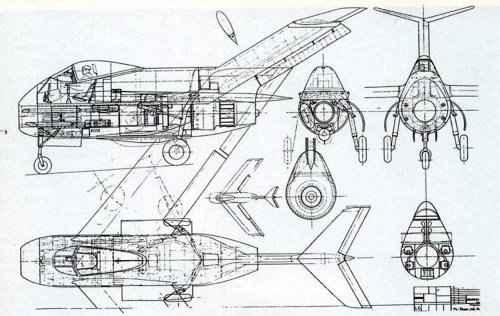
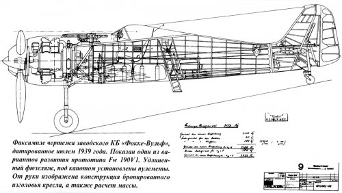
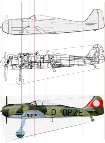
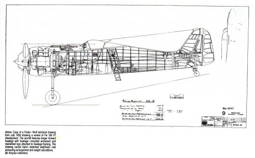
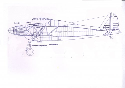
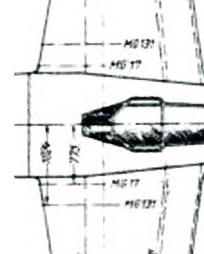
"The facsimile of the factory drawing of the Focke-Wulf Design Bureau,
Dated July 1939. One of the
Development of the prototype Fw 190 V1. The elongated
fuselage, machine guns are installed under the hood.
The armored headboard of the chair, and the calculation of the mass."

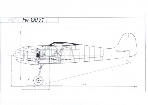
From what I read, the V1 prototype had no fuselage mounted guns, the whole
armament should be installed in the wings.
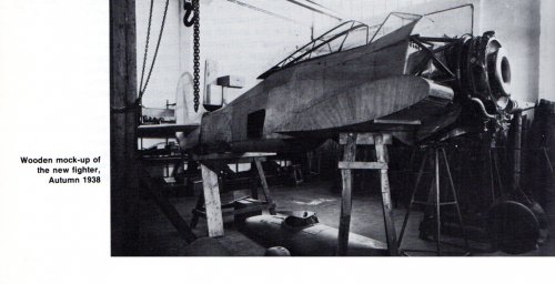
The cockpit is positioned further aft in this drawing. This is said to have been the
result of the change to the heavier BMW 801 engine and allowed installation
of the fuselage mounted guns.
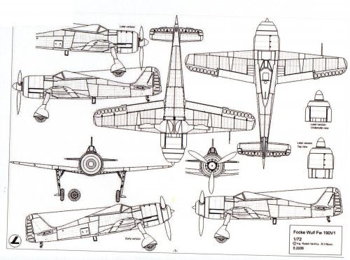
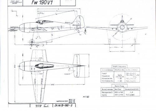
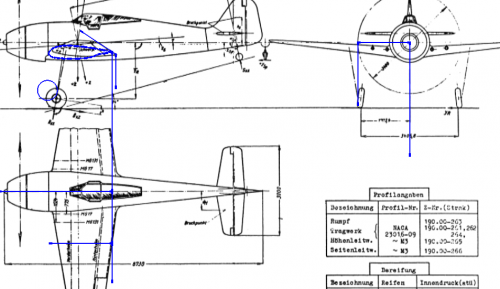
I've tried to check this drawing against two drawings of the V1 (via https://cernunninsel.files.wordpress.com/2014/06/focke-wulf-fw-190-v1-dreiseitenansicht.jpg,
originally published in the German magazine "Klassiker der Luftfahrt" and via https://forum.warthunder.com/index.php?/topic/145474-first-flight-of-the-fw-190-1st-june/)

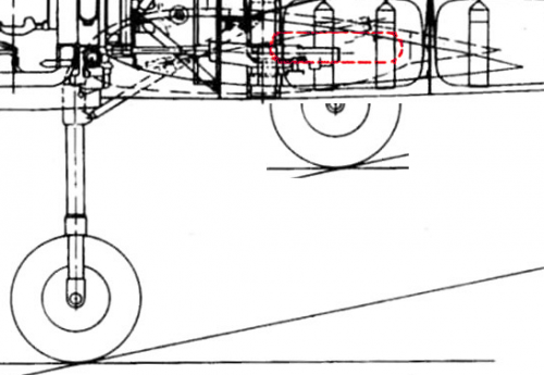
Judging typical points (wing attachment points at the fuselage, junction of tail section and
fuselage) length seems to coincide with the V1, so perhaps it actually shows changes to take
the BMW 801 engines and increased armament. Then the date 1939 for this drawing would be
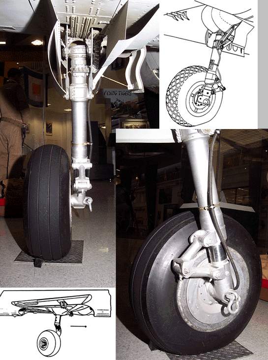
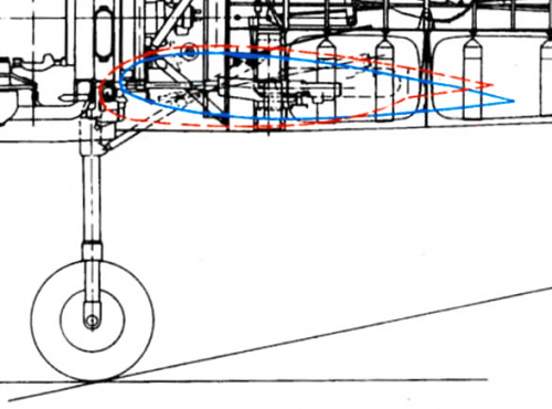
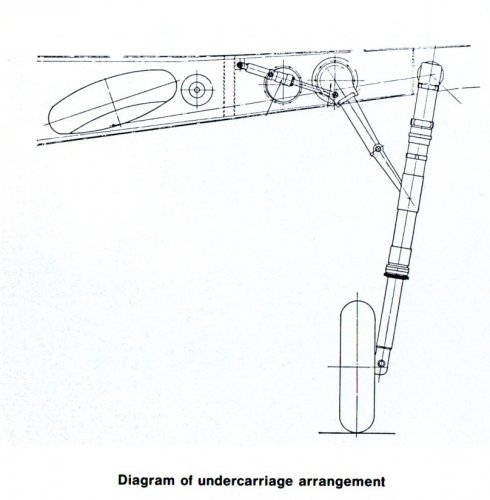
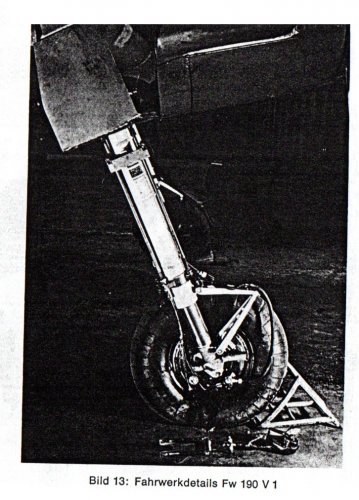
logical, but ... that landing gear then makes no sense at all, because the wide tracked landing
gear was regarded as an important advantage to the Bf 109 and certainly nothing, that would
have been relinquished recklessly.
 

Attachments

  • 190V1.jpg
    190V1.jpg
    187.2 KB · Views: 560
Could we possibly be looking at a prototype specifically intended for the attention of the Kriegsmarine? Something built with company funds to back up a unsolicited proposal in other words?
 
In 1939 there actually was an interest in carrier aircraft and that year the Bf 109T was chosen,
so an unsolicited proposal doesnn't sound implausible to me, especially as the Bf 109T was intended
to be launched via a cradle, a more elaborate procedure, than just using the landing gear. But wouldn't
a robust, wide tracked landing gear, as built into the Fw 190 from the start, not have been better, than
this one ? And I canot see an arrestor hook, as on all other German carrier aircraft.
 
Justo Miranda said:
Probably an early pproposed configuration.

Hello, Justo!

What's connection between Swedish and German fighters?
They have entirely different fuselage structure - and, in the same time several common external elements.
Anyway, FW design, IMHO, was earlier, then SAAB.

Their much more FW-190 versions and built aircraft - with all respect to SAAB design (which didn't see combat).

Thanks for the picture sharing - these types have some common in their design!
 
Justo Miranda said:
The undercarriage folding system may be similar of the drawing posted by Sienar

I don't think so - J-22 has main undercarriage, retracting into fuselage compartments. We could see this on the pictures, you kindly provided.
In my humble opinion, this FW-190' drawing could depict undercarriage retracting mechanism, similar to Curtiss P-40, where main leg retracts under lower wing surface (and didn't intersect main spar) - with a wheel, accommodating well between spars.
P40gears.jpg


The illustration from the Russian book is a kind of mystery. If we could find it's origin, perhaps, more details could be cleared. I winder, if the rounded rectangle, that we see didn't related to the undercarriage at all. Changing wing structure just to incorporate design of high-wing monoplane (FW-159) should require a number of advantages at this decision.

At least, we has a good riddle at this factory drawing!

Again - thanks to J-22 drawings, nice aircraft!
 
The book doesnt give any source for the drawing unfortunately.

The strangest thing is the depicted wing section, one of which looks bulged for the gear, but the other has its trailing edge further back than the first, which is odd.

There is also this scribble to the side of the drawing that I originally cropped out, but looking at it a second time it appears like it might be a rough top down view of the gear.
 

Attachments

  • 190 myst.png
    190 myst.png
    147.7 KB · Views: 243
  • side drawing.jpg
    side drawing.jpg
    54 KB · Views: 202
Additional info
 

Attachments

  • img237.jpg
    img237.jpg
    123.8 KB · Views: 147
  • img236.jpg
    img236.jpg
    199.1 KB · Views: 160
  • img235.jpg
    img235.jpg
    433.3 KB · Views: 221
  • img234.jpg
    img234.jpg
    797.3 KB · Views: 237
  • img233.jpg
    img233.jpg
    340.2 KB · Views: 255
  • img231.jpg
    img231.jpg
    315.5 KB · Views: 278
  • img230.jpg
    img230.jpg
    273.3 KB · Views: 301
Many thanks, Justo, especially for the higher res and so nearly readable
verson of the drawing in question (Could you please tell us, where you found it ?)
The description as "a variant of Fw 190 V1" nevertheless isn't really accurate, as the
V1 already had made its maiden flight in June 1939 and for such profound modifications
certainly another prototype would have been built.
Perhaps a reason for changing the landing gear to a fuselage mounted type could have
been the wish to free up the complete wing for the installatin of armament ?
 
Perhaps a reason for changing the landing gear to a fuselage mounted type could have
been the wish to free up the complete wing for the installatin of armament ?

Thus providing room for 4 x MG 151/20 in the wing roots?
 

Attachments

  • img241.jpg
    img241.jpg
    462.7 KB · Views: 231
  • img242.jpg
    img242.jpg
    90.8 KB · Views: 211
I noted, that machine guns, incorporated into wing root, have been fed by ammunition boxes.
These boxes definitely placed inside fuselage, because their height exceeds wing height in any possible section.
Could this drawing depicts one of the FW-190 possible developments, with sleigh forward-swept wing, in order, to maintain the CG in desired location?

In that case wing airfoil, drawn by continuos line would be wing root section, and dashed-one - section of main undercarriage fitting, with a bulge on lower surface (similar to Curtiss) P-40?

This is just my own speculation.
I see at least one possible reason of such redesign - to place all MG close to the fuselage: above engine and in the wing roots.

Actual FW-190 undercarriage retraction scheme, IMHO, prevents such placement.
Update: I was wrong about this - there were certain versions of FW-190 with wing-root installed armament. Looks, like undercarriage leg just passed lower, then gun' barrels

Hope, somebody would find the real source of this drawing with a comments!
 
During the week I will look in the German boo­k­a­zine FLUGZEUG CLASSIC Extra 14 Focke-Wulf Fw 190, if there is some more Info and pictures regarding a variant of Fw 190 V1.
If so, I will write a quick summary. Since this boo­k­a­zine is still available at books stores near train stations, I will not post any pictures as attachments. ;)
 
I found the page https://forum.warthunder.com/index.php?/topic/167285-the-development-of-the-fw-190-from-mockup-to-a-1/, that described FW-190 early prototypes and mentions:
The first FW-190 designs were quite different from those we all know and love. Mockups used four MGs in the wing root similar to the later armament in that spot, two MG 131 and MG 17 were proposed. The landing gear also differed; it used a rearward-retracting undercarriage similar to the US P-36 and P-40 which quickly were abandoned for the sake of aerodynamics, and the wings and tail also differed, the most striking feature only employed in the prototypes however was the Tunnelnabe, a special type of propeller hub aiming to eliminate drag.

Sources: Fw 190 Volume One, Luftwaffe Classics series by J. Richard Smith and Eddie J. Creek
Wikipedia.org
www.focke-wulf190.com

Perhaps, Smith/Creek book contains the information of unusual undercarriage?
 
That gave me an idea. What if the landing gear wasnt mounted near the fuselage, but in bulges under the wing?

This would explain what seems strange about the dotted wing section, because if that is the root and the colid section is outboard then there is some aft sweep and anhedral going on. However if it is a bulge outboard, then some things line up in just the right way.

As for why this might have been looked at? The wing planform of the v1 was different than the production version, with quite a bit more sweep on the leading edge and a perfectly straight front spar. The production version with its tweaked planform required the front spar being kinked aft to allow the wheel space for stowage.

I would now guess that this is some midterm design between the v1 and the pre-production versions.
 

Attachments

  • gdffffddd.png
    gdffffddd.png
    220.4 KB · Views: 1,113
  • 190v5 scale.png
    190v5 scale.png
    477.3 KB · Views: 1,138

Similar threads

Back
Top Bottom