
You are using an out of date browser. It may not display this or other websites correctly.
You should upgrade or use an alternative browser.
You should upgrade or use an alternative browser.
US Supersonic Transport (SST) Program 1960-1971
- Thread starter Orionblamblam
- Start date
blackkite
Don't laugh, don't cry, don't even curse, but.....
- Joined
- 31 May 2007
- Messages
- 8,821
- Reaction score
- 7,721
Attachments
...and the first XB-70 was really a pig of aircraft. To the point they demoted it to Mach 2.5 and no more.
The second one was better but ran into a
F-104 of course.
The second one was better but ran into a
F-104 of course.
I'd tended to believe that the people designing the NAC-60 also looked at the B-70 and saw a number of things they didn't want to do again. Maybe for them, using compression lift was a mistake. One thing not to be repeated was the complexity of the Valkyrie's landing gear. I'd say that to go from the Valkyrie to the NAC-60, they were looking to simplify things. The military tends to tolerate maintenance costs the airlines wouldn't put up with.
Post #175 by Skybolt regarding compression lift :
"Regarding compression lift, they didn't apply it simply because (I am oversemplificating, I must admit) there isn't anything like compression lift in the real world... The lift generated by the shockwave is compensated by additional drag. This was proved in the windtunnel at Langley since 1959, and later confirmed in flight testing of the XB-70. See NASA report TM-X-76 "An Experimental Pressure-Distribution Investigation of Interference Effects produced at a Mach number of 3.11 by Wedge-Shaped Bodies Located under a Triangular Wing". http://hdl.handle.net/2060/19670022631"
"Regarding compression lift, they didn't apply it simply because (I am oversemplificating, I must admit) there isn't anything like compression lift in the real world... The lift generated by the shockwave is compensated by additional drag. This was proved in the windtunnel at Langley since 1959, and later confirmed in flight testing of the XB-70. See NASA report TM-X-76 "An Experimental Pressure-Distribution Investigation of Interference Effects produced at a Mach number of 3.11 by Wedge-Shaped Bodies Located under a Triangular Wing". http://hdl.handle.net/2060/19670022631"
blackkite
Don't laugh, don't cry, don't even curse, but.....
- Joined
- 31 May 2007
- Messages
- 8,821
- Reaction score
- 7,721
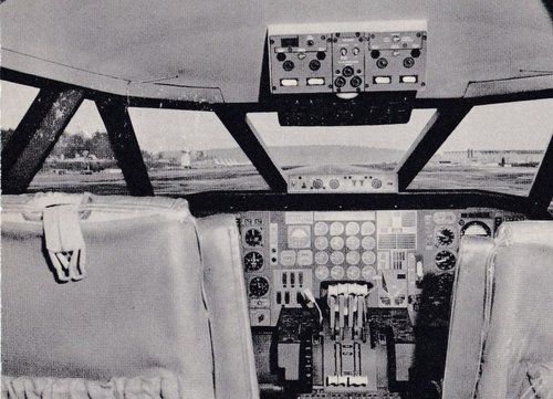
Interesting shape visor. Not drooped nose. Is it enough?
https://planetskier.blogspot.com/2017/08/santa-monica-and-commercial-aviations.html


https://planetskier.blogspot.com/2017/08/santa-monica-and-commercial-aviations.html


Attachments
Last edited:
blackkite
Don't laugh, don't cry, don't even curse, but.....
- Joined
- 31 May 2007
- Messages
- 8,821
- Reaction score
- 7,721
Hi!
Source : Skybolt-san's contribution in page3.


Source : Skybolt-san's contribution in page3.
- All 733-197 type (733-197(prototype?) domestic type and, intercontinental type) wings were same size. And all type used same engine GE4/J4C.
- Surprisingly length of domestic type and intercontinental type were same.(249’ 5”) where prototype length was 203’ 10”.
- Main difference between domestic type and intercontinental type is take off engine power. Domestic type engine power is 85% dry power. Intercontinental type engine power is after burning power. So intercontinental noise is large.


Last edited:
blackkite
Don't laugh, don't cry, don't even curse, but.....
- Joined
- 31 May 2007
- Messages
- 8,821
- Reaction score
- 7,721
Lockheed CL-823 was a competitor of Boeing 733-197 at SST phaseⅠstudy in early 1964.
There are some data for number of passengers.


There are some data for number of passengers.


Last edited by a moderator:


Johnbr
ACCESS: Top Secret
- Joined
- 6 May 2007
- Messages
- 753
- Reaction score
- 329


Last edited:
blackkite
Don't laugh, don't cry, don't even curse, but.....
- Joined
- 31 May 2007
- Messages
- 8,821
- Reaction score
- 7,721
Phase ⅡA SST study in November 1964, Lockheed offered following designs.
All design had same wing, eigine, landing gear, flight station, vertical stabilizer, and take off gross weight. (Source : Lockheed horizons)
1. L-2000-1, Small intercontinental type, 170 seats, length : 65.23m(214ft)
2. L-2000-2, Large intercontinental type, 221 seats, Length : 68.8m(225.7ft)
3. L-2000-3, Domestic type,250 seats, Length : 74.9m(245.7ft)
Boeing offered B733-290.
Phase ⅡB SST study in 1965, Boeing offered B733-362.
Also studied SCAT15F and judged unfavorable because of poor low speed performance and high development risk.
Please try automatic translator. Very interesting site.
 testpilot.ru

All design had same wing, eigine, landing gear, flight station, vertical stabilizer, and take off gross weight. (Source : Lockheed horizons)
1. L-2000-1, Small intercontinental type, 170 seats, length : 65.23m(214ft)
2. L-2000-2, Large intercontinental type, 221 seats, Length : 68.8m(225.7ft)
3. L-2000-3, Domestic type,250 seats, Length : 74.9m(245.7ft)
Boeing offered B733-290.
Phase ⅡB SST study in 1965, Boeing offered B733-362.
Also studied SCAT15F and judged unfavorable because of poor low speed performance and high development risk.
Please try automatic translator. Very interesting site.
Lockheed L-2000
ÐÑÐ¾ÐµÐºÑ ÑвеÑÑзвÑкового паÑÑажиÑÑкого ÑамолеÑа Lockheed L-2000
testpilot.ru

Last edited by a moderator:
blackkite
Don't laugh, don't cry, don't even curse, but.....
- Joined
- 31 May 2007
- Messages
- 8,821
- Reaction score
- 7,721
Phase ⅡB SST study in 1965, Lockheed studied L-2000-4,-5 and-6. (Source : Lockheed Horizons)
L-2000-4 was a modified L-2000-2.
Design change points from L-2000-2 to L-2000-4 are as follows.
1. Slightly change to the leading and trailing-edge sweep angle.
2. Refinement of wing twist and camber.
3. Upsweep of the forward delta or chine for trim.
4. Addition of leading edge flaps for better subsonic and transonic lift/drag ratio.
The potential maximum lift/drag ratio at cruise for the L-2000-4 was about 8.3.
L-2000-5 was a SCAT15F.
L-2000-6 was a ( (L-2000-4)+(L-2000-5))/2.
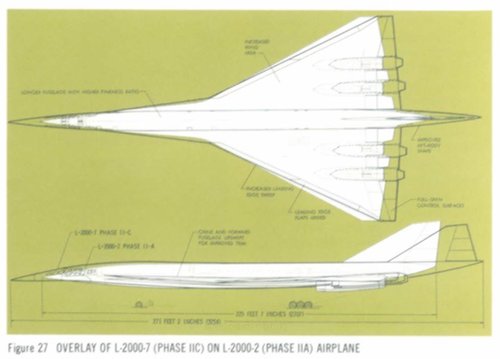
Later L-2000-4 was developped into L-2000-7.

L-2000-4 was a modified L-2000-2.
Design change points from L-2000-2 to L-2000-4 are as follows.
1. Slightly change to the leading and trailing-edge sweep angle.
2. Refinement of wing twist and camber.
3. Upsweep of the forward delta or chine for trim.
4. Addition of leading edge flaps for better subsonic and transonic lift/drag ratio.
The potential maximum lift/drag ratio at cruise for the L-2000-4 was about 8.3.
L-2000-5 was a SCAT15F.
L-2000-6 was a ( (L-2000-4)+(L-2000-5))/2.
Later L-2000-4 was developped into L-2000-7.

Last edited:


blackkite
Don't laugh, don't cry, don't even curse, but.....
- Joined
- 31 May 2007
- Messages
- 8,821
- Reaction score
- 7,721
Hi! Boeing 2707-200 model(upper one) and -100 model. Horizontal tail stabilizer shape is different from -100.
 www.airspacemag.com


The History of Boeing in 15 Objects
A rummage through the airplane maker’s attic.


Last edited:
blackkite
Don't laugh, don't cry, don't even curse, but.....
- Joined
- 31 May 2007
- Messages
- 8,821
- Reaction score
- 7,721
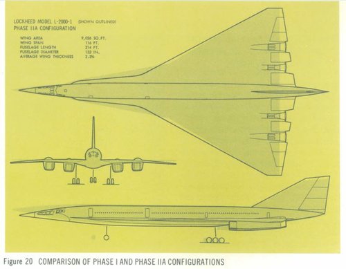
Lockheed SST design improvement from phaseⅠ(1963) to phaseⅡA(June 1964)
(Source : lockheed horizons)
Design change points.
Phase ⅡA design features.
(Range and minimum payload are FAA requirement)
(Source : lockheed horizons)
- L/D : 7.25 to 7.94
- Increase longitudinal stability at angle of attack 36degree.
- Complete elimination of pitch-up.
- The powerful wing leading edge vortex provide directional stability at 20degree angle of attack and side slip angle as high as 30degree.
Design change points.
- Wing area : 8370ft2 (778.6m2)to 9026ft2(839.6m2)
- Large basic delta wing area increased.
- Forward delta wing area decreased.
- Forward delta wing sweep back angle : 80degree to 85degree.
- Wing average thickness : 3.0% to 2.3%.
- Wing twist, camber increased.
Phase ⅡA design features.
(Range and minimum payload are FAA requirement)
- Number of passengers : 170 to 250(L-2000-1 : 170, L-2000-2 : 221,L-2000-3 : 250).
- Range : 4000 statute miles (6437km)
- Minimum payload : 30000lb(17280kg)
- Cruising speed : Mach3.
Attachments
Last edited:
blackkite
Don't laugh, don't cry, don't even curse, but.....
- Joined
- 31 May 2007
- Messages
- 8,821
- Reaction score
- 7,721
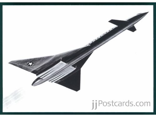
What is this post card? This design had six engines.
")
blackkite
Don't laugh, don't cry, don't even curse, but.....
- Joined
- 31 May 2007
- Messages
- 8,821
- Reaction score
- 7,721
blackkite
Don't laugh, don't cry, don't even curse, but.....
- Joined
- 31 May 2007
- Messages
- 8,821
- Reaction score
- 7,721


blackkite
Don't laugh, don't cry, don't even curse, but.....
- Joined
- 31 May 2007
- Messages
- 8,821
- Reaction score
- 7,721
Japanese explanation is as follows.
「The US supersonic transport project
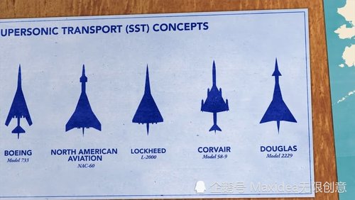
Three proposals for a supersonic transport in the United States that have been attracting attention were announced by the FAA (Federal Aviation Administration).
In the United States, aircraft manufacturers have begun developing supersonic passenger aircraft for five to six years.
However, the development cost of supersonic transport was so large that every company was hesitant to develop and produce it.
However, at the end of 1962, it was decided to produce a Concorde supersonic transport in the UK and France, so FAA was asked to submit design proposals for the supersonic transport from Boeing, Lockheed, and North American under the order of President Kennedy.
Also, P & W, GE, and Curtiss Wright submitted engine design proposals.
Three proposals for the aircraft were announced by the FAA this time, but the FAA plans to select the best design proposal for the aircraft and engine from the plans of each company by May 1964. (At present, the US government plans to subsidize 75% of development costs.)
As for engines, it’s believed that P & W has two types of turbofan engine plans, GE has one turbojet engine plan and one turbofan engine plan, and Curtiss Wright has one turbojet engine plan.
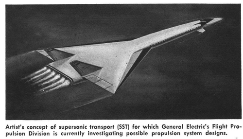
Looking at the aircraft drawings of each company, the shape, dimensions, and performance differ considerably among the company plans.
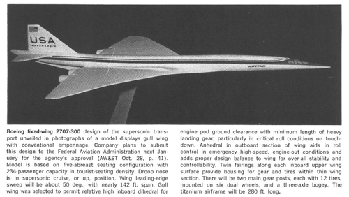
Boeing's proposal uses a variable sweep back angle system for the main wing. The FAA recommended the main wings with a variable sweep back angle system for each company, but this would be a problem in terms of mechanism and operating technology. Boeing has also announced plans to extend the length of the aircraft and install 227 passenger seats.
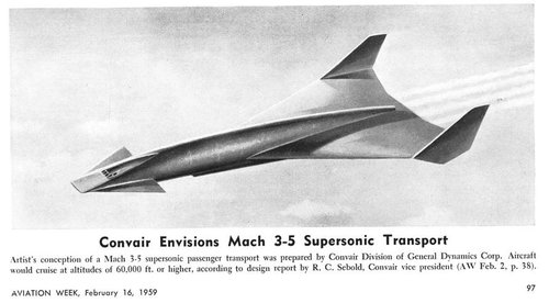
Lockheed's proposal is about twice as heavy as the Concorde supersonic transport in terms of weight and number of passengers, the largest of the three, and the fastest cruising speed Mach 3.
According to the Lockheed plan, the main wing is a double delta wing without a horizontal tail, and it is considered to increase the number of passengers by increasing the diameter of the fuselage.
The North American proposal has the same canard type of the XB-70, and does not have a mechanism to improve visibility because the angle of attack during landing does not large.
(same as XB-70 and Douglas 2229, but Sukhoi T-4 is different.)
The United States supersonic transport development competition is likely to become the biggest topic in the world's aviation in the 1960s.」
I think unknown P&W turbofan engine was a afterburning turbofan engine same as TF30.
What is the type of GE turbofan engine? GE4/J5 base engine?
「The US supersonic transport project
Three proposals for a supersonic transport in the United States that have been attracting attention were announced by the FAA (Federal Aviation Administration).
In the United States, aircraft manufacturers have begun developing supersonic passenger aircraft for five to six years.
However, the development cost of supersonic transport was so large that every company was hesitant to develop and produce it.
However, at the end of 1962, it was decided to produce a Concorde supersonic transport in the UK and France, so FAA was asked to submit design proposals for the supersonic transport from Boeing, Lockheed, and North American under the order of President Kennedy.
Also, P & W, GE, and Curtiss Wright submitted engine design proposals.
Three proposals for the aircraft were announced by the FAA this time, but the FAA plans to select the best design proposal for the aircraft and engine from the plans of each company by May 1964. (At present, the US government plans to subsidize 75% of development costs.)
As for engines, it’s believed that P & W has two types of turbofan engine plans, GE has one turbojet engine plan and one turbofan engine plan, and Curtiss Wright has one turbojet engine plan.
Looking at the aircraft drawings of each company, the shape, dimensions, and performance differ considerably among the company plans.
Boeing's proposal uses a variable sweep back angle system for the main wing. The FAA recommended the main wings with a variable sweep back angle system for each company, but this would be a problem in terms of mechanism and operating technology. Boeing has also announced plans to extend the length of the aircraft and install 227 passenger seats.
Lockheed's proposal is about twice as heavy as the Concorde supersonic transport in terms of weight and number of passengers, the largest of the three, and the fastest cruising speed Mach 3.
According to the Lockheed plan, the main wing is a double delta wing without a horizontal tail, and it is considered to increase the number of passengers by increasing the diameter of the fuselage.
The North American proposal has the same canard type of the XB-70, and does not have a mechanism to improve visibility because the angle of attack during landing does not large.
(same as XB-70 and Douglas 2229, but Sukhoi T-4 is different.
)The United States supersonic transport development competition is likely to become the biggest topic in the world's aviation in the 1960s.」
I think unknown P&W turbofan engine was a afterburning turbofan engine same as TF30.
What is the type of GE turbofan engine? GE4/J5 base engine?
Last edited:
- Joined
- 26 May 2006
- Messages
- 34,924
- Reaction score
- 15,796
Attachments
blackkite
Don't laugh, don't cry, don't even curse, but.....
- Joined
- 31 May 2007
- Messages
- 8,821
- Reaction score
- 7,721
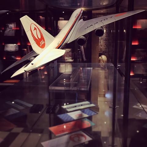
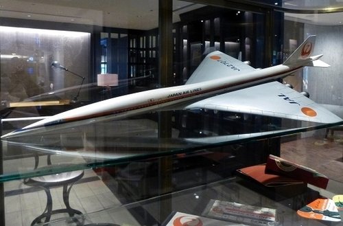
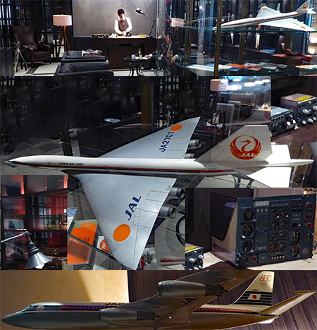
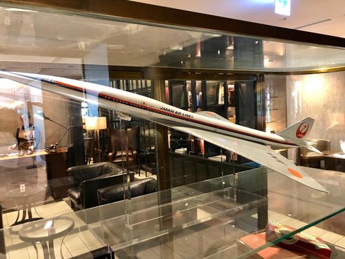
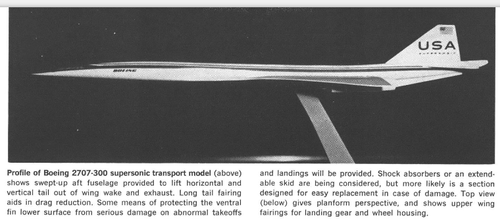
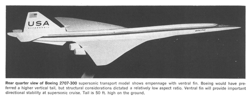
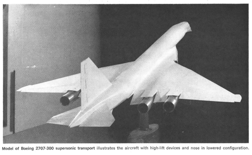
Hi! Tokyo Haneda airport JAL international route first class lounge exhibition model which galgot-san taught me.
This model shows B2707-300 prototype, not operational model. Enjoy.
【Haneda Airport International Terminal Complete Guide】The excitement does not stop before the trip in the space like a theme park.

 haveagood.holiday
This model shows B2707-300 prototype, not operational model. Enjoy.
【Haneda Airport International Terminal Complete Guide】The excitement does not stop before the trip in the space like a theme park.
ä¸æ¥ä¸æ¥½ããã¡ããï¼ç¾½ç°ç©ºæ¸¯ç¬¬3ã¿ã¼ããã«å®å¨ã¬ã¤ã
ç¾½ç°ç©ºæ¸¯ç¬¬3ã¿ã¼ããã«ã¯2010å¹´ã«éæ¥ããã¿ã¼ããã«ã§ããæ±æ¸ãã¤ã¡ã¼ã¸ããéãããã£ãããæ¥æ¬ã®åã表ç¾ããã¦ãã¦æµ·å¤ããæ¥æ¬ã«æ¥ãæ¹ã楽ããããããªå·¥å¤«ãããã¦ãã¾ããã ããããæ¥æ¬ãåçºè¦ã§ãããããªä»æãããããããä¼æ¥ã®ãåºããã«ãã´ã£ããã®ã¹ãããã§ãã
Attachments
Last edited:
blackkite
Don't laugh, don't cry, don't even curse, but.....
- Joined
- 31 May 2007
- Messages
- 8,821
- Reaction score
- 7,721
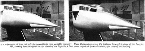
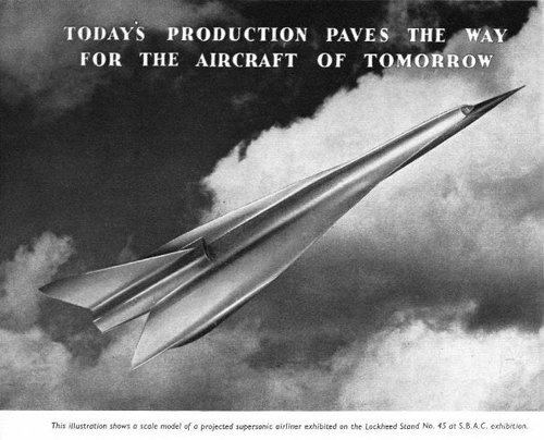
Caption of this picture is as follows.
"The illustration shows a scale model of a projected supersonic airliner exhibited on the Lockheed stand No45 at S.B.A.C. exhibition."
(S.B.A.C. : Society of British Aerospace Companies)
 speedbirdconcorde.wixsite.com
"The illustration shows a scale model of a projected supersonic airliner exhibited on the Lockheed stand No45 at S.B.A.C. exhibition."
(S.B.A.C. : Society of British Aerospace Companies)
GALLERY | speedbirdconcorde
Attachments
Last edited:
- Joined
- 26 May 2006
- Messages
- 34,924
- Reaction score
- 15,796
Attachments
blackkite
Don't laugh, don't cry, don't even curse, but.....
- Joined
- 31 May 2007
- Messages
- 8,821
- Reaction score
- 7,721
Drag Reduction of the L-2000-7 (Source : Lockheed Hrizons)
Drag Reduction of the L-2000-7 was carried out by use of advanced aerodynamic techniques and methods developed by NASA.
These included, among others,
Drag Reduction of the L-2000-7 was carried out by use of advanced aerodynamic techniques and methods developed by NASA.
These included, among others,
- Improvement in longitudinal area distribution.
- Optimization of wing camber and twist.
- Application of favorable interference principles.
- Adoption of leading edge flaps.
Attachments
Last edited:
blackkite
Don't laugh, don't cry, don't even curse, but.....
- Joined
- 31 May 2007
- Messages
- 8,821
- Reaction score
- 7,721
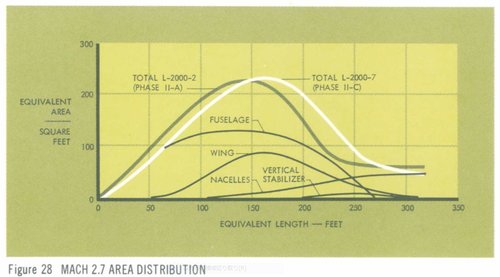
(1) Improvement in longitudinal area distribution.
The L-2000-2 airplane was characterized by a Mach 2.7 equivalent area distribution of relatively low nose-fineness ratio and rather abrupt aft closure.
Progress refinements to the fuselage, wing, nacelle, and vertical tail geometries were adopted to obtain the improvement shown in Figure 28.
The increased nose-fineness ratio and the smoothed aft closure are apparent.
The L-2000-7 overall area distribution is substantially better than that of the L-2000-2 airplane and results in reduced wave drag.
Attachments
blackkite
Don't laugh, don't cry, don't even curse, but.....
- Joined
- 31 May 2007
- Messages
- 8,821
- Reaction score
- 7,721
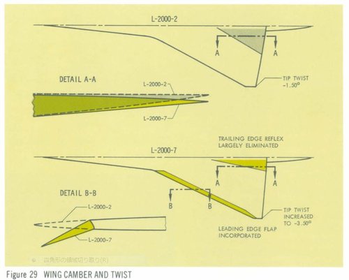
(2)Optimization of wing camber and twist.
The camber and twist distributions of the L-2000-7 wing have been substantially altered from those of the L-2000-2 airplane.
Upward inclination of the forward fuselage and forward-delta surface introduced favorable longitudinal trimming moment with minimum drag penalty.
This change, in conjunction with increased wing twist and camber, has made it possible to improve the wing design at the trailing edge.
Figure 29 shows the nature and extent of these changes.
In addition, a leading edge flap been incorporated for use at all speeds up to and including the transonic region. The combination of this leading edge flap, the change in airfoil twist and camber and the improvement in the wing trailing-edge reflex is the source of marked aerodynamic improvements throughout the entire speed envelope.
Attachments
blackkite
Don't laugh, don't cry, don't even curse, but.....
- Joined
- 31 May 2007
- Messages
- 8,821
- Reaction score
- 7,721
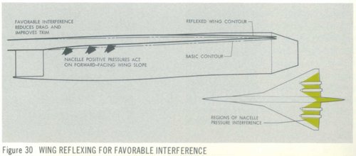
(3)Application of favorable interference principles.
Another advanced aerodynamic technique, development at the NASA-Langley Laboratory, has been applied to wing contours in regions affected by the pressure fields generated by the large under-wing nacelles. Research results on the SCAT-15F model and others showed that favorable interference effects could be attained by altering wing contours in this vicinity of the nacelles.
This allows positive pressure fields generated by the nacelles to fall on forward-facing slopes of the wing.
Shown in Figure 30, this design refinement is referred to as “wing reflexing ” and its effects of favorable nacelle-wing interference have been realized both in drag reduction and improved longitudinal trim.
(Little looks like compression lift?)
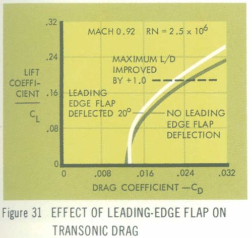
(4)Adoption of leading edge flaps.
Lift/drag ratio improvements have also been accomplished in other portions of the high-speed flight spectrum by use of the leading-edge flap.
Tests at Cornell Laboratory and the NASA-Ames Laboratory have shown that deflection of the leading-edge flap results in drag reduction at Mach numbers as high as 1.4.
As shown in Fig 31, test data at model scale show a direct improvement of a full unit in lift/drag ratio at a Mach number of 0.92.
Although improvement due to leading-edge flap are reduced at higher transonic speeds, they are still significance.
Another advanced aerodynamic technique, development at the NASA-Langley Laboratory, has been applied to wing contours in regions affected by the pressure fields generated by the large under-wing nacelles. Research results on the SCAT-15F model and others showed that favorable interference effects could be attained by altering wing contours in this vicinity of the nacelles.
This allows positive pressure fields generated by the nacelles to fall on forward-facing slopes of the wing.
Shown in Figure 30, this design refinement is referred to as “wing reflexing ” and its effects of favorable nacelle-wing interference have been realized both in drag reduction and improved longitudinal trim.
(Little looks like compression lift?)
(4)Adoption of leading edge flaps.
Lift/drag ratio improvements have also been accomplished in other portions of the high-speed flight spectrum by use of the leading-edge flap.
Tests at Cornell Laboratory and the NASA-Ames Laboratory have shown that deflection of the leading-edge flap results in drag reduction at Mach numbers as high as 1.4.
As shown in Fig 31, test data at model scale show a direct improvement of a full unit in lift/drag ratio at a Mach number of 0.92.
Although improvement due to leading-edge flap are reduced at higher transonic speeds, they are still significance.
Attachments
Last edited:
Thanks Blackkite-San.
All these are from Lockheed Horizons revue ?
All these are from Lockheed Horizons revue ?
- Joined
- 26 May 2006
- Messages
- 34,924
- Reaction score
- 15,796
Thanks Blackkite-San.
All these are from Lockheed Horizons revue ?
Yes of course.
Attachments
blackkite
Don't laugh, don't cry, don't even curse, but.....
- Joined
- 31 May 2007
- Messages
- 8,821
- Reaction score
- 7,721
Yes galgot-san.Thanks Blackkite-San.
All these are from Lockheed Horizons revue ?
NASA also did good work for the SST at the day.
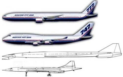
Please confirm B2707 size.
Attachments
Last edited:
blackkite
Don't laugh, don't cry, don't even curse, but.....
- Joined
- 31 May 2007
- Messages
- 8,821
- Reaction score
- 7,721
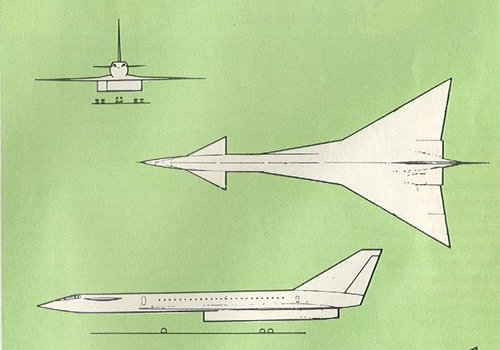
Justo-san's contribution about Douglas 2229 SST three side view drawing is excellent. This drawing is the best we have. May be an official one.
Unfortunately no aircraft size in this drawing. If someone measure the length of full scale mockup of 2229 SST cockpit in Santa Monica, we can guess the size of this aircraft.
I like this commandment.
Don't laugh, don't cry, don't even curse, but understand.(Baruch De Spinoza)
Unfortunately no aircraft size in this drawing. If someone measure the length of full scale mockup of 2229 SST cockpit in Santa Monica, we can guess the size of this aircraft.
I like this commandment.
Don't laugh, don't cry, don't even curse, but understand.(Baruch De Spinoza)
Attachments
Last edited:
martinbayer
ACCESS: Top Secret
- Joined
- 6 January 2009
- Messages
- 3,402
- Reaction score
- 3,911
Blackkite, the Douglas SST cockpit section at the Santa Monica Museum of Flying is also a scale model, probably around 1/5 or so, but definitely not full size. Still, measuring wouldn't hurtJusto-san's contribution about Douglas 2229 SST three side view drawing is excellent. This drawing is the best we have. May be an official one.
Unfortunately no aircraft size in this drawing. If someone measure the length of full scale mockup of 2229 SST cockpit in Santa Monica, we can guess the size of this aircraft.
Don't laugh, don't cry, don't even curse, but understand.(Baruch De Spinoza)
...Martin
Last edited:
blackkite
Don't laugh, don't cry, don't even curse, but.....
- Joined
- 31 May 2007
- Messages
- 8,821
- Reaction score
- 7,721
Thanks a lot!!
Museum of flying in Santa Monica also have a scale model of whole 2229 SST. If only we know the scale.......
Anyway detailed examination of this official model is necessary.
According to this model, the number of seats rows on this airliner is 26, and if there are six seats in one row, the total is 156 seats. If there are five seats in a row, there are 130 seats in total.

 acesflyinghigh.wordpress.com
Museum of flying in Santa Monica also have a scale model of whole 2229 SST. If only we know the scale.......
Anyway detailed examination of this official model is necessary.
According to this model, the number of seats rows on this airliner is 26, and if there are six seats in one row, the total is 156 seats. If there are five seats in a row, there are 130 seats in total.


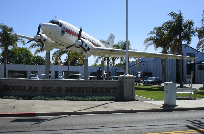
The Spirit of Santa Monica Douglas DC-3 Monument – A Tribute to Donald Douglas Senior
In 1927 the Douglas Aircraft Corporation was established in Santa Monica, California by Donald Wills Douglas Senior (April 6th, 1892 – February 1st, 1981). His impact on the aviation industry was l…
acesflyinghigh.wordpress.com
Last edited:
martinbayer
ACCESS: Top Secret
- Joined
- 6 January 2009
- Messages
- 3,402
- Reaction score
- 3,911
blackkite, keep in mind that supersonic planes tend to be slender due to drag considerations, and both the Concorde and Tu-144 hat rows with only 4 seats abreast. That roughly jibes with the description of the Douglas 2229 as a 100 seat aircraft at https://en.wikipedia.org/wiki/Douglas_2229.
Martin
Martin
Similar threads
-
 FLIGHTS OF FANTASY: The Lockheed L-2000 SST in airline service
- Started by Sentinel Chicken
- Replies: 9
-
 Could the US have built an SST?
- Started by uk 75
- Replies: 35
-
-
-
