
You are using an out of date browser. It may not display this or other websites correctly.
You should upgrade or use an alternative browser.
You should upgrade or use an alternative browser.
The STAMP (Small tactical aerial mobility platform) Program
- Thread starter Rickshaw
- Start date
- Joined
- 11 March 2006
- Messages
- 8,625
- Reaction score
- 3,806
Have found the same photo on my HD, it's from Aviation Week 1974, 6-12
and at least the principle of the propulsion system was shown there .Can have
another look at this issue at the library, but this would take some time ... :-\
and at least the principle of the propulsion system was shown there .Can have
another look at this issue at the library, but this would take some time ... :-\
compton_effect
ACCESS: Confidential
- Joined
- 13 June 2007
- Messages
- 77
- Reaction score
- 38
Talk about a FOD nightmare.
funkychinaman
ACCESS: Restricted
- Joined
- 10 November 2008
- Messages
- 33
- Reaction score
- 1
Looks like something out of GI Joe.
- Joined
- 4 May 2008
- Messages
- 2,439
- Reaction score
- 762
rickshaw said:My question is, why didn't it lead to bigger, brighter things, if it worked?
even if you can make it work, the fuel weight penalty deriving from lifting the whole vehicle using thrust alone for 100% of the flight time (vs. wing lift) would probably limit endurance and military utility.
- Joined
- 17 October 2006
- Messages
- 2,393
- Reaction score
- 1,197
To paraphrase Ron White, the range is probably just about enough to get you to the crash site.
- Joined
- 3 June 2011
- Messages
- 18,338
- Reaction score
- 12,240
LowObservable said:To paraphrase Ron White, the range is probably just about enough to get you to the crash site.
If it had seats that would bounce you out of a cornfield it'd be okay though wouldn't it? ;D
Matej
Multiuniversal creator
samardza said:http://contrails.iit.edu/DigitalCollection/1986/AFWALTR86-3071volume01.pdf
Fantastic document packed with the hundreds of pages with the interesting stuff (Lockheed VATOL studies or Snecma Coléoptére to name a few).
- Joined
- 27 December 2005
- Messages
- 17,748
- Reaction score
- 26,422
A great doc that I posted here in 2007:
http://www.secretprojects.co.uk/forum/index.php/topic,2907.0/highlight,afwal.html
;D
http://www.secretprojects.co.uk/forum/index.php/topic,2907.0/highlight,afwal.html
;D
Matej
Multiuniversal creator
I realized it when I wanted to save it and found, that I already have it. Well, I enjoyed with the great enthusiasm the same thing two times, what can be better? 
Garrett STAMP
Source: http://sobchak.wordpress.com/2009/08/03/stamp-small-tactical-aerial-mobility-platform/
Source: http://sobchak.wordpress.com/2009/08/03/stamp-small-tactical-aerial-mobility-platform/
Attachments
Hi All
New to this forum so sorry if this is in the wrong place.
When I was a kid in the '70s I used to read a magazine called Speed and Power, and one issue had an article about a proposed light battlefield VTOL aircraft for the US Army called a S.T.A.M.P.
I think the acronym stood for "small tactical airborne multirole platform".
Does anyone else remember this? I largely have drawn a blank in numerous searches over the years. It vaguely resembled a Westland Scout without rotors or tailboom, IIRC. It might have been manufactured by Garrett.
Cheers
Rich
jstar
ACCESS: Secret
- Joined
- 12 October 2007
- Messages
- 346
- Reaction score
- 425
Attachments
- Joined
- 25 June 2009
- Messages
- 14,753
- Reaction score
- 6,154
Here is an article from Flight International (7 March 1974) which contained all three pics that Triton posted further up here:
Garrett's flying jeep
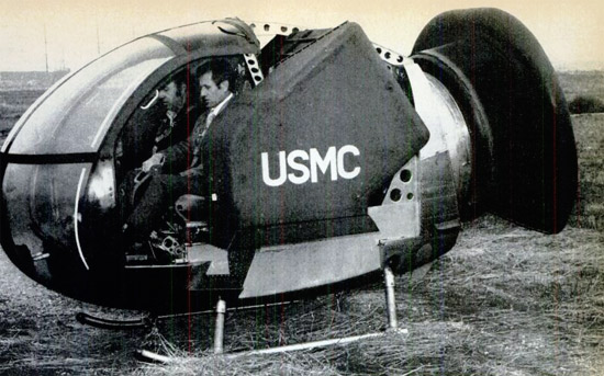
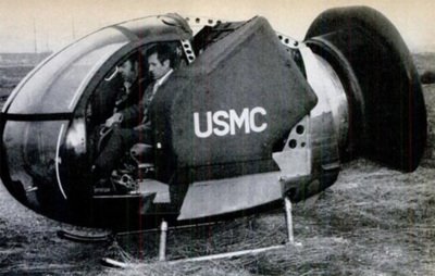
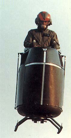
Garrett's Stamp (Small Tactical Aerial Mobility Platform), which made its first, tethered, flight on December 21 last year, is the latest in a long series of American attempts to devise a practicable minimum-size vehicle—a flying jeep in fact.
Built under a $500,000 contract from the United States Marine Corps, the Stamp is a vectored-thrust Vtol feasibility demonstrator comprising the forward fuselage of a Hughes OH-6A helicopter with rotor system, engine and tailboom removed, and a 474 s.h.p. Garrett TSE231 turboshaft engine substituted. This powerplant drives a 6,000 r.p.m. ducted fan, specially built for the application by
Garrett, which generates the thrust needed for lift, motion in the horizontal plane, control and trim.
The project began in December 1972 when the USMC negotiated the contract and supplied the company with the helicopter; Garrett identified itself with this high-risk venture by providing the engine. A similar contract was awarded to Williams Research for its Wasp (Williams Aerial Systems Platform), see Flight for February 21, page 251. The design was undertaken by a floating establishment of up to a dozen Garrett engineers under the technical direction of the Naval Weapons Centre at China Lake, Calif.
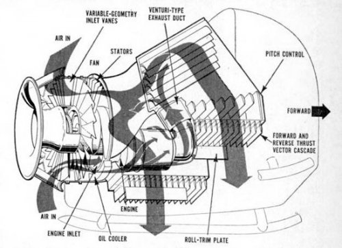
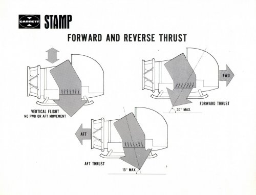
The drawings on this page show how the jet-lift system works. The fan is located at the rear of the vehicle and sucks in air from an aft-facing intake. The flow is mixed with the hot turbine exhaust, which increases thrust and cuts down infrared emission (an important military consideration, says Garrett), and is divided into two streams which pass either side of the fuselage by means of twin-branched ducts.
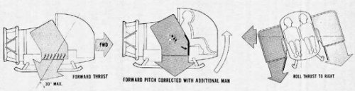
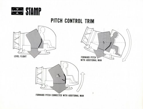
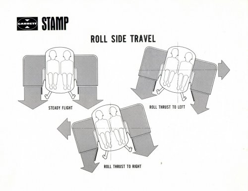
Four sets of fixed cascades, two in each branch of the duct, direct the flow vertically downwards to sustain the vehicle in flight. Forward and reverse thrust for translational flight is obtained by rotating two more sets of cascades, one in each duct, to divert the flow in the appropriate direction. Pitch and roll attitude changes are accomplished by moving simple diverter plates in the airflow via the pilots' controls.
Garrett told Flight recently that, despite the limited flying time so far —a mere 3min—it had verified the vehicle in a qualitative manner. The very tight budget called for heavy reliance on intuitive design and there are little electronics or other sophistry. Despite this limitation the vehicle is described as "manageable"; yaw control is said to be good, though pitch control is only marginal, and it is skittish in roll.
It is not clear whether the company will go forward to the next stage, the construction of a more realistic prototype based on theoretical and windtunnel investigation. This vehicle would have a maximum speed and altitude of 75 m.p.h. and 5,000ft respectively,
a range of 30 miles and an endurance of 30min.
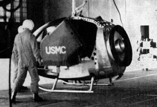
The Stamp feasibility demonstrator weighs 6701b and measures 8ft long by 6ft wide and 6ft high. Air enters the engine through the bellmouth intake at the rear of the fuselage and is exhausted through the rectangular ducts on each side. No ejection seats are fitted for the two-man crew, though crew safety in a fully engineered prototype will be a matter of some priority. The drawing on the left shows the airflow through the engines, while the diagrams, below, illustrate how the thrust is diverted to provide attitude control and horizontal movement by means of deflector plates and variable-angle cascades mounted in the ducts
Garrett's flying jeep
Garrett's Stamp (Small Tactical Aerial Mobility Platform), which made its first, tethered, flight on December 21 last year, is the latest in a long series of American attempts to devise a practicable minimum-size vehicle—a flying jeep in fact.
Built under a $500,000 contract from the United States Marine Corps, the Stamp is a vectored-thrust Vtol feasibility demonstrator comprising the forward fuselage of a Hughes OH-6A helicopter with rotor system, engine and tailboom removed, and a 474 s.h.p. Garrett TSE231 turboshaft engine substituted. This powerplant drives a 6,000 r.p.m. ducted fan, specially built for the application by
Garrett, which generates the thrust needed for lift, motion in the horizontal plane, control and trim.
The project began in December 1972 when the USMC negotiated the contract and supplied the company with the helicopter; Garrett identified itself with this high-risk venture by providing the engine. A similar contract was awarded to Williams Research for its Wasp (Williams Aerial Systems Platform), see Flight for February 21, page 251. The design was undertaken by a floating establishment of up to a dozen Garrett engineers under the technical direction of the Naval Weapons Centre at China Lake, Calif.
The drawings on this page show how the jet-lift system works. The fan is located at the rear of the vehicle and sucks in air from an aft-facing intake. The flow is mixed with the hot turbine exhaust, which increases thrust and cuts down infrared emission (an important military consideration, says Garrett), and is divided into two streams which pass either side of the fuselage by means of twin-branched ducts.
Four sets of fixed cascades, two in each branch of the duct, direct the flow vertically downwards to sustain the vehicle in flight. Forward and reverse thrust for translational flight is obtained by rotating two more sets of cascades, one in each duct, to divert the flow in the appropriate direction. Pitch and roll attitude changes are accomplished by moving simple diverter plates in the airflow via the pilots' controls.
Garrett told Flight recently that, despite the limited flying time so far —a mere 3min—it had verified the vehicle in a qualitative manner. The very tight budget called for heavy reliance on intuitive design and there are little electronics or other sophistry. Despite this limitation the vehicle is described as "manageable"; yaw control is said to be good, though pitch control is only marginal, and it is skittish in roll.
It is not clear whether the company will go forward to the next stage, the construction of a more realistic prototype based on theoretical and windtunnel investigation. This vehicle would have a maximum speed and altitude of 75 m.p.h. and 5,000ft respectively,
a range of 30 miles and an endurance of 30min.
The Stamp feasibility demonstrator weighs 6701b and measures 8ft long by 6ft wide and 6ft high. Air enters the engine through the bellmouth intake at the rear of the fuselage and is exhausted through the rectangular ducts on each side. No ejection seats are fitted for the two-man crew, though crew safety in a fully engineered prototype will be a matter of some priority. The drawing on the left shows the airflow through the engines, while the diagrams, below, illustrate how the thrust is diverted to provide attitude control and horizontal movement by means of deflector plates and variable-angle cascades mounted in the ducts
- Joined
- 17 October 2006
- Messages
- 2,393
- Reaction score
- 1,197
There is basically only one problem with such vehicles, which is that in the event of a propulsion failure at any time in flight they drop like a rock, and quite likely tumble in the process.
Jos Heyman
ACCESS: Top Secret
- Joined
- 15 February 2007
- Messages
- 597
- Reaction score
- 80
This is what I have found on the Williams WASP, developed for the STAMP programme:
Flight 21 Feb 1974, p. 251
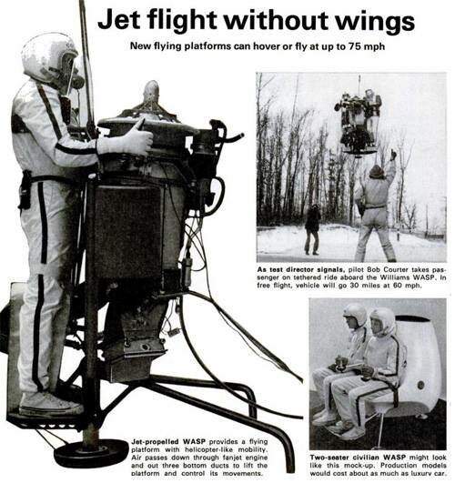
A two-man turbine-powered flying platform, developed under a US Navy contract, has been successfully tested in a series of tethered flights. Wasp (Williams aerial systems platform) has been built by Williams Research for the Marine Corps' Stamp (Small tactical aerial mobility platform) R&D programme, which requires a vehicle for frontline liaison, reconnaissance, mine detection, communications and rescue. Wasp can carry two men for 30min at 60 m.p.h., following a vertical takeoff, and is powered by a 7001b-thrust Williams WR-19 turbofan which can be uprated to 1,1001b. Empty weight is 2701b.
http://www.rocketbelts.americanrocketman.com/jet-pack.html
Initial flight tests of the one and two man WASP (Williams Aerial Systems Platform), a turbine powered flying platform developed by William Research Corporation of Walled Lake, Michigan. Powered by the world's smallest fanjet engine, the WASP is designed to take off vertically, accelerate rapidly, move forward, backward, sideways, hover, rotate and enable one or two men to fly for 30 minutes at speeds of 60 miles per hour. Flown here on a safely tether line used during early trails tests - by test pilot Robert Courter and with passenger Jack Benson , the WASP was built and demonstrated under a U.S. Marine Corps research and development program STAMP (Small Tactical Aerial Mobility Platform).
I have also a pic of the WASP. I thought I had this downloaded from this forum but I cannot find it here - so I have no idea where I got it.
BTW, this WASP should not be confused with the 1982 WASPII for the US Army, which was a totally different vehicle.
Flight 21 Feb 1974, p. 251
A two-man turbine-powered flying platform, developed under a US Navy contract, has been successfully tested in a series of tethered flights. Wasp (Williams aerial systems platform) has been built by Williams Research for the Marine Corps' Stamp (Small tactical aerial mobility platform) R&D programme, which requires a vehicle for frontline liaison, reconnaissance, mine detection, communications and rescue. Wasp can carry two men for 30min at 60 m.p.h., following a vertical takeoff, and is powered by a 7001b-thrust Williams WR-19 turbofan which can be uprated to 1,1001b. Empty weight is 2701b.
http://www.rocketbelts.americanrocketman.com/jet-pack.html
Initial flight tests of the one and two man WASP (Williams Aerial Systems Platform), a turbine powered flying platform developed by William Research Corporation of Walled Lake, Michigan. Powered by the world's smallest fanjet engine, the WASP is designed to take off vertically, accelerate rapidly, move forward, backward, sideways, hover, rotate and enable one or two men to fly for 30 minutes at speeds of 60 miles per hour. Flown here on a safely tether line used during early trails tests - by test pilot Robert Courter and with passenger Jack Benson , the WASP was built and demonstrated under a U.S. Marine Corps research and development program STAMP (Small Tactical Aerial Mobility Platform).
I have also a pic of the WASP. I thought I had this downloaded from this forum but I cannot find it here - so I have no idea where I got it.
BTW, this WASP should not be confused with the 1982 WASPII for the US Army, which was a totally different vehicle.
Attachments
- Joined
- 25 June 2009
- Messages
- 14,753
- Reaction score
- 6,154
Very interesting. Thanks!
This makes me think that Williams's WASP was a competitor to Garrett's STAMP. Probably for the same tender, but I think that STAMP was Garrett's name, not the program's name...
The project began in December 1972 when the USMC negotiated the contract and supplied the company with the helicopter; Garrett identified itself with this high-risk venture by providing the engine. A similar contract was awarded to Williams Research for its Wasp (Williams Aerial Systems Platform)
This makes me think that Williams's WASP was a competitor to Garrett's STAMP. Probably for the same tender, but I think that STAMP was Garrett's name, not the program's name...
- Joined
- 25 June 2009
- Messages
- 14,753
- Reaction score
- 6,154

- Joined
- 17 October 2006
- Messages
- 2,393
- Reaction score
- 1,197
I expect the pilot acquired the callsign "Oscar".
"Oh I love trash!" ;D
Jos Heyman
ACCESS: Top Secret
- Joined
- 15 February 2007
- Messages
- 597
- Reaction score
- 80
I understand these were two different developments, for different customers and in different time frames but both part of a series of Williams projects. WASP=STAMP was for USMC, the X-Jet was WASP II and was for US Army. So, except for being part of Williams' WASP programme, there was no connections between the two. There may even have been further designs in the WASP seriers.Stargazer2006 said:In the same way that the STAMP demonstrator was very different from the planned product, the Williams WASP demonstrator (also called the X-Jet) was also a far cry from the artist's concept... at least from an aesthetic viewpoint!
Hi fellows,
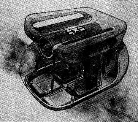
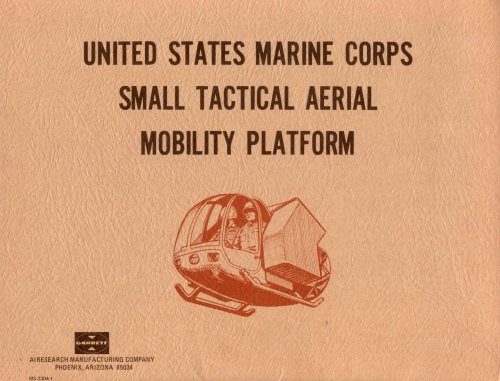
as always, digging in my archives looking for a totally different matter, I found a brochure about the garrett AiResearch STAMP. As I love anything looking as flying jeep "et similia", I perused It looking for pictures but the folder contained only some drawings but I think you could appreciate.
The related press release is dated december 21, 1973 and says: "Garrett STAMP vehicle tested successfully".
The demonstration - we can read on the release - was made today in a two-man vehicle at the U. S. Marine Corps Air Station El Toro, California. The test was a successfull tethered flight of the proof-of-concept vehicle that was an heavily modified Hughes OH-6A Cayse's fuselage with a Garrett AiResearch TSE 231 turboshaft engine.
In the folder there are some paper version of a slide show (but only test, no picture), that I think is worth reading.
#1
Garrett's STAMP feasibility Demonstration
# 2
Purpose of demonstration
Completion demonstration of a one year contract (No 0123-73-C-1073) for the United States Marine Corps, managed by Naval Weapons Center, China Lake.
Three-part demonstration with color film coverage (but, sorry, as I already told you, any sort of picture was attached)
+ Build a vehicle with correct weight-power balance
+ One man demonstrating controlability of vehicle for simple maneuvers
+Two man demonstration=show daylight under vehicle.
# 3
Vital Statistics
STAMP vehicle:
Modified LOH helicopter fuselage
Simple control system
Dry weight - 660 lbs (299 kg)
Fuel capacity - 10 gals (38 liters)
Overall dimensions- 6 ft x 6 ft x 8 ft (1,83 m x 1,83 m x 2,44 m)
Payload-Two men
Thrust/Weight - 1.2 one man 1.1 two men
Ducted fan design (103 lbs/sec 47 kg/sec) air flow; 1.08:1 pressure ratio; lifting thrust 1050 libs (476 kg/st); bypass ratio 25:1.
Garrett TSE 231 engine:
Rated at 474 sHP (sea level static day)
Fuel consumption 0.605 lbs/HP/h (0,264 kg)
Output shaft speed 6000 rpm
# 4
Garrett STAMP design goal
Small size- two man side-by-side seating
Range - 30 miles (48 km)
Endurance - 30 min (minimum)
Ability to hover - Simplicity of operation
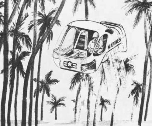
Ability to penetrate tree canopy
Low noise level
Minimum erosive action on landing and takeoff surfaces
Ability to perform power-off approach and landing
Appropriate ground handlig provisions
Ability to retrieve another STAMP vehicle
On the leaflet we can read some other data: the design goals of the proposed vehicle are: maximum speed 75 mph (121 km/h), maximum altitude 5,000 ft (1.525 m).
I enclose the various graphs contained in the folder
Nico
as always, digging in my archives looking for a totally different matter, I found a brochure about the garrett AiResearch STAMP. As I love anything looking as flying jeep "et similia", I perused It looking for pictures but the folder contained only some drawings but I think you could appreciate.
The related press release is dated december 21, 1973 and says: "Garrett STAMP vehicle tested successfully".
The demonstration - we can read on the release - was made today in a two-man vehicle at the U. S. Marine Corps Air Station El Toro, California. The test was a successfull tethered flight of the proof-of-concept vehicle that was an heavily modified Hughes OH-6A Cayse's fuselage with a Garrett AiResearch TSE 231 turboshaft engine.
In the folder there are some paper version of a slide show (but only test, no picture), that I think is worth reading.
#1
Garrett's STAMP feasibility Demonstration
# 2
Purpose of demonstration
Completion demonstration of a one year contract (No 0123-73-C-1073) for the United States Marine Corps, managed by Naval Weapons Center, China Lake.
Three-part demonstration with color film coverage (but, sorry, as I already told you, any sort of picture was attached)
+ Build a vehicle with correct weight-power balance
+ One man demonstrating controlability of vehicle for simple maneuvers
+Two man demonstration=show daylight under vehicle.
# 3
Vital Statistics
STAMP vehicle:
Modified LOH helicopter fuselage
Simple control system
Dry weight - 660 lbs (299 kg)
Fuel capacity - 10 gals (38 liters)
Overall dimensions- 6 ft x 6 ft x 8 ft (1,83 m x 1,83 m x 2,44 m)
Payload-Two men
Thrust/Weight - 1.2 one man 1.1 two men
Ducted fan design (103 lbs/sec 47 kg/sec) air flow; 1.08:1 pressure ratio; lifting thrust 1050 libs (476 kg/st); bypass ratio 25:1.
Garrett TSE 231 engine:
Rated at 474 sHP (sea level static day)
Fuel consumption 0.605 lbs/HP/h (0,264 kg)
Output shaft speed 6000 rpm
# 4
Garrett STAMP design goal
Small size- two man side-by-side seating
Range - 30 miles (48 km)
Endurance - 30 min (minimum)
Ability to hover - Simplicity of operation
Ability to penetrate tree canopy
Low noise level
Minimum erosive action on landing and takeoff surfaces
Ability to perform power-off approach and landing
Appropriate ground handlig provisions
Ability to retrieve another STAMP vehicle
On the leaflet we can read some other data: the design goals of the proposed vehicle are: maximum speed 75 mph (121 km/h), maximum altitude 5,000 ft (1.525 m).
I enclose the various graphs contained in the folder
Nico
Attachments
shedofdread
ACCESS: Top Secret
- Joined
- 14 November 2009
- Messages
- 593
- Reaction score
- 400
Hmmm... Interesting... Control [effectively] by weight shift, eh? Not sure I'd volunteer for that one I imagine that were that STAMP thingy to get built, the first update would include 'puffers' for more precise control.
I imagine that were that STAMP thingy to get built, the first update would include 'puffers' for more precise control.I stumbled across a video of the Williams X-Jet WASP that I had never seen before. It appears to be documenting the training and test flights of a group of army personnel. Most impressive are the long duration flights taken through and over forests. I wish some internet billionaire might take this concept and apply current technology in jet engines and lightweight materials to see what can be achieved.
I did a search to see if this topic had been covered before but the closest I could find was the "STAMP" project. If there is an existing thread for this or the video is already posted, please delete.
https://www.youtube.com/watch?v=uXNNc_HFodI
I did a search to see if this topic had been covered before but the closest I could find was the "STAMP" project. If there is an existing thread for this or the video is already posted, please delete.
https://www.youtube.com/watch?v=uXNNc_HFodI
- Joined
- 25 June 2009
- Messages
- 14,753
- Reaction score
- 6,154
Very interesting! I think this really belongs in the Postwar projects section and as a modest contribution to the subject, here are three photos of the X-Jet prototype (don't know if there were more than one) and the planned WASP cabin vehicle design for the Marines.
Attachments
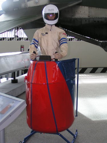
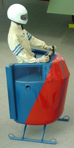

Do the guys in the white jumpsuits work for Ernst Stavro Blofeld?
shedofdread
ACCESS: Top Secret
- Joined
- 14 November 2009
- Messages
- 593
- Reaction score
- 400
- Joined
- 1 May 2007
- Messages
- 2,595
- Reaction score
- 1,965
Y'know, if you put wheels on it, and arranged for the engine to drive the wheels, so you could drive around on the ground when you didn't HAVE to fly, you could call it the 'Jumping Jeep' . . .
cheers,
Robin.
- Joined
- 9 October 2009
- Messages
- 21,976
- Reaction score
- 13,638
I think that was actually a nickname for the STAMP.you could call it the 'Jumping Jeep'
- Joined
- 27 September 2006
- Messages
- 6,417
- Reaction score
- 6,818
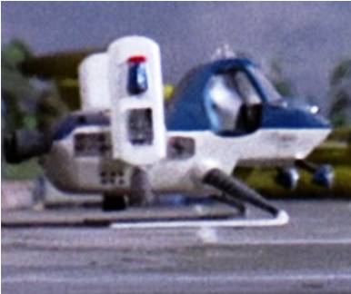
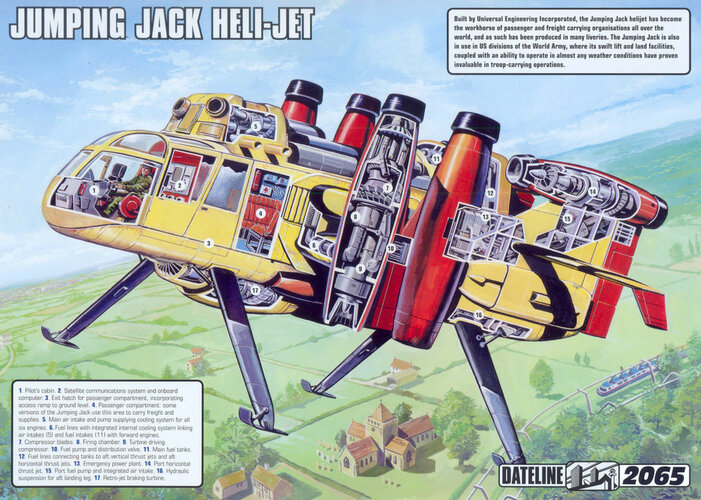
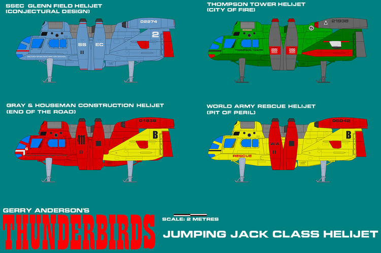
As usual the late Gerry Anderson and his modelmakers were on the case
 thunderbirds.fandom.com
A larger version called the "Jumping Jack" was a frequent guest star in "Thunderbirds" see attached.
thunderbirds.fandom.com
A larger version called the "Jumping Jack" was a frequent guest star in "Thunderbirds" see attached.
Now if only I could talk to my friends using a teapot like Lady Penelope...
Police Helijet
The Police Helijet is a vehicle that appears in several Thunderbirds season 1 episodes. It is usually seen parked on the ground in an airport scene. The Police Helijet appears on Somportex gum card no. 49 (First Series). A plastic model kit was produced by Japanese company Imai, and sold as part...
Now if only I could talk to my friends using a teapot like Lady Penelope...
Attachments
- Joined
- 25 January 2020
- Messages
- 1,279
- Reaction score
- 1,954
What exactly would have this been used for, and would it have carried armament? I can only imagine that it was outmoded by helicopters, for economical reasons and noise restraints.
Similar threads
-
-
AFFDL Tactical High Altitude Penetrator (THAP)
- Started by CFE
- Replies: 48
-
 ASD Preliminary Designs in Splendid Vision, Unswerving Purpose
- Started by XP67_Moonbat
- Replies: 16
-

-
Char AMХ-30 with Garrett GT601 gas-turbine engine
- Started by Kiril Romassyov
- Replies: 17