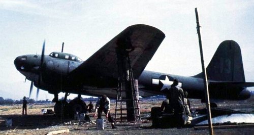
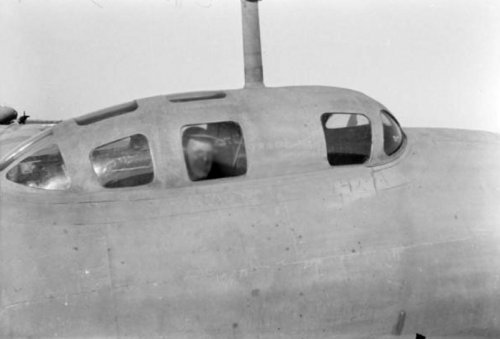
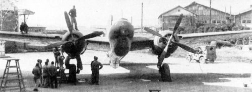
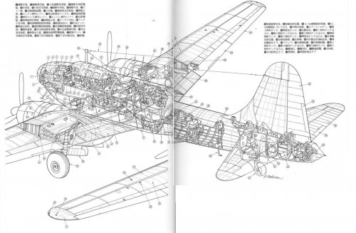
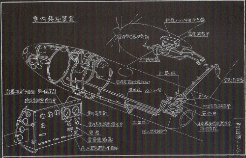
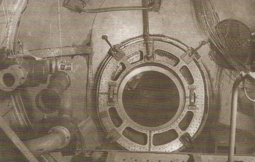
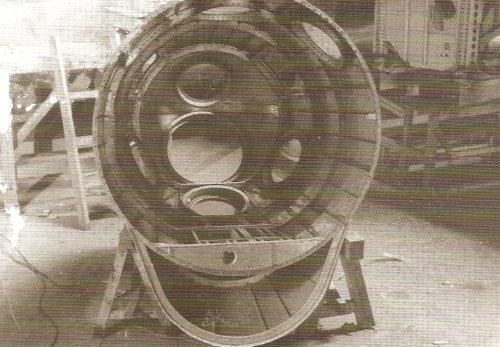
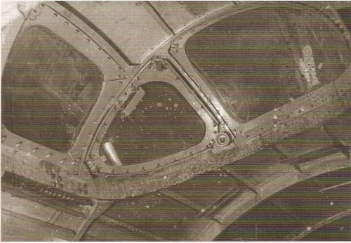
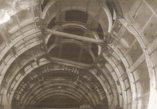
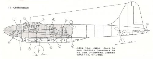
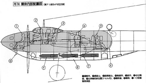
Hi! Cockpit structure taken from the nose and front wind shield.
You can see offset wind shield and reinforcement bar to withstand cockpit inner pressure in the first picture.
Cabin pressurising air was intercooler cooling air (after cooling hot air).
Hi Alcides san! Thank you for your attention. I will give you some more information about Ki-74. Please wait.
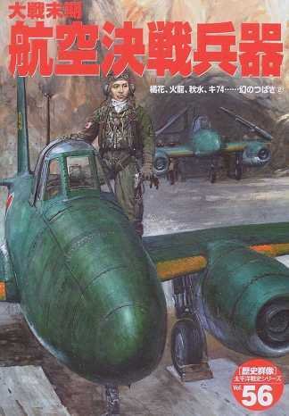
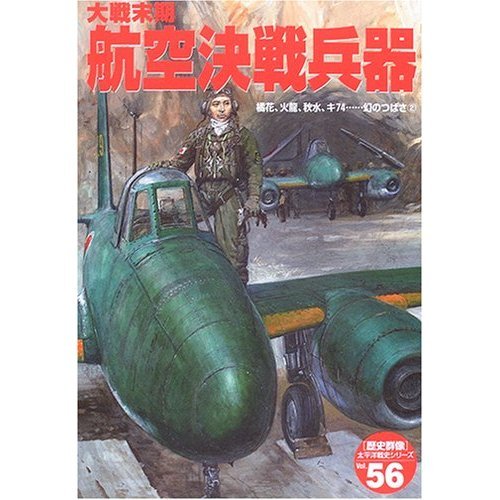
Source : Gakken "大戦末期 航空決戦兵器 (Late war aerial battle weapons)" ISBN4-05-604536-4
I think that the technology which applied to the Ki-74 was very useful for Fugaku design at the day.
Nakajima asked Tachikawa to deliver pressurized cabin technology for Ki-87Ⅱdesign.
Thanks a lot my dear hesham.
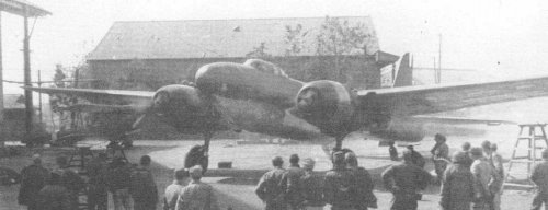
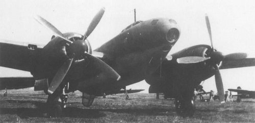
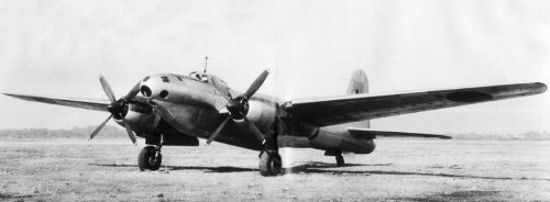
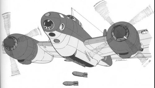
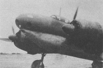
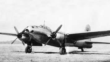
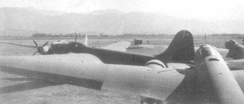
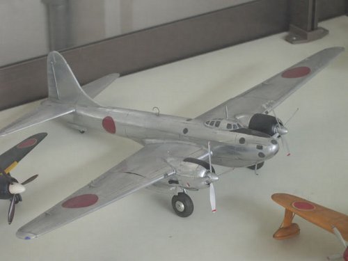
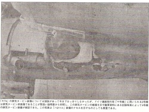
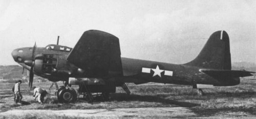
Ki-74's engine was turbo charged Nakajima HA-211ru Homare with forced cooling fan.
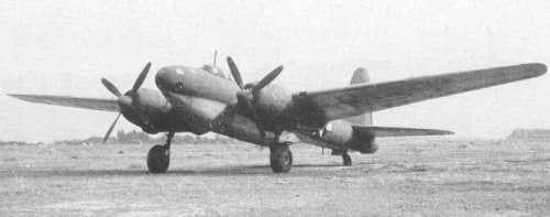
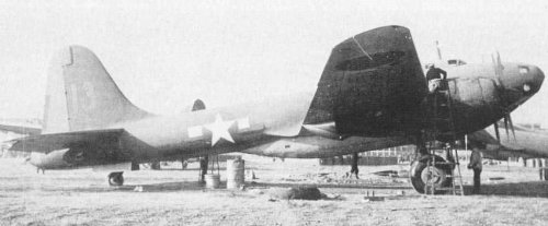
Also Ki-74 had a pressurized cabin and remote controled tail turret. Ki-74 was a very advanced aircraft in Japan at the day.
Nakajima aircraft asked Tachikawa to deliver pressurized cabin technology for Fugaku bomber.
I imagine that Nakajima also asked Tachikawa to deliver remote control turret technology for Fugaku bomber,too.
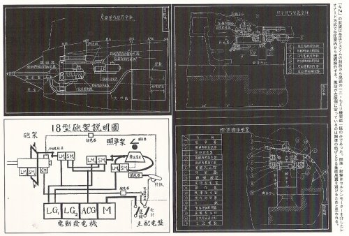
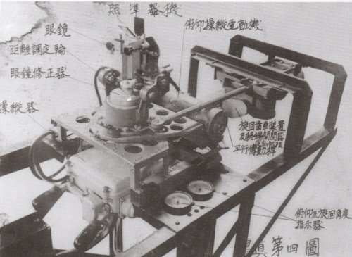
A sight and shooting of a tail remote machine gun were Leonard system through a self synchronizing motor.
ACG : AC generator?
SM : Self synchronizing motor?
M : Motor?
CM : Charge motor?
LG : Some kind of generator?
LM : Some kind of electric equipment?
Someone please help me. :-[
Perhaps
SM1 : Turning control motor
SM2 : Turning control motor
SM3 : Elevation control motor
SM4 : Elevation control motor
LM1 : Turning movement limitation circuit breaker
LM2 : Turning angle transmitter
LM3 : Elevation movement limitation circuit breaker
LM4 : Elevation angle transmitter
LG1,LG2 : ?
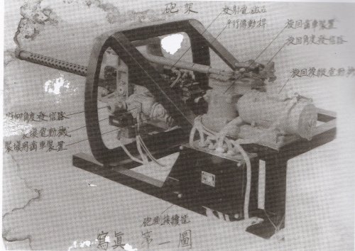
寫眞第二圖 : No.2 picture
駐退器 : Recoil brake、揺架 : Cradle、俯仰歯車機構: Elevation gear mechanism、旋回俯仰操縦電動機 Turning Elevation control motor
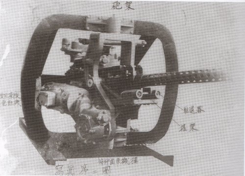
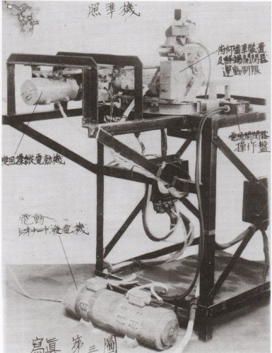
寫眞第三圖 : No.3 picture
俯仰歯車装置及運動制限開閉器 : Elevation gear and movement limitation circuit breaker、操作盤 : Control panel、旋回操縦電動機 : Turning control motor、電動発電機 : Electric drive generator
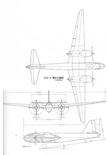
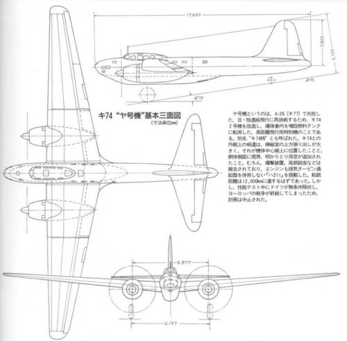
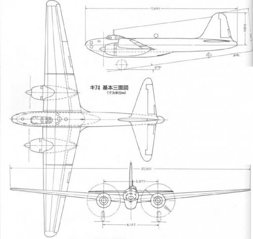
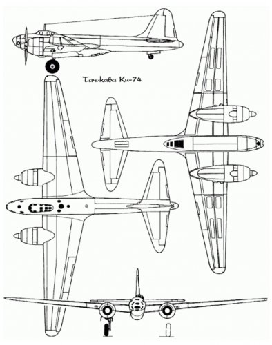
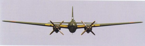
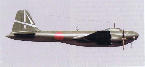
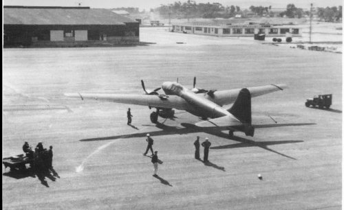
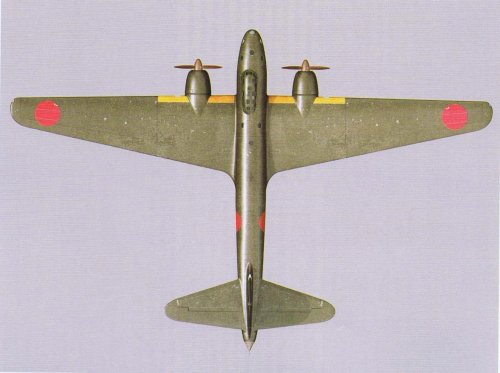
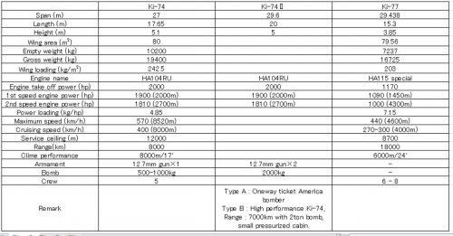
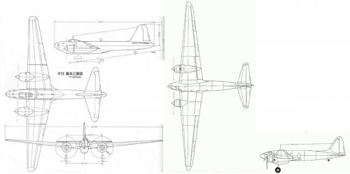
Ki 74-II
A long-range bomber type that was developed in April 1944. This machine was also called "Ya-Go." The scale of the aircraft was expanded to a total length of 20. 0 m, a total width of 29. 6 m, and a total height of 5. 5 m, and the engine became the Mitsubishi "Ha 211 Le". The fuselage has also been redesigned, the pressurized cabin became only at the nose part. The cockpit shifted to the front, smoothly connected to the fuselage, resembling a normal double-seat bomber. There are 7 passengers. Due to the work delay caused by the air raid and the evacuation, only the mockup was produced and the war ended.
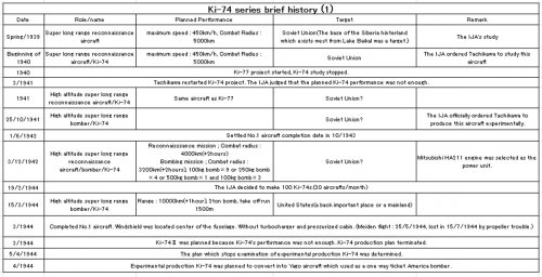
Ki 74-Ⅱ Type A(Ko)
A mainland US bombing plane with an emphasis on long range cruising performance. The number of crews was reduced to three, and the total fuel capacity was increased to 12,000 liters by using only two 500 kg bombs. The cruising range was planned to be 8,000 km, and it was supposed to make a one-way attack against the mainland US. Completion of the first prototype was scheduled for August 1944.
Ki 74-Ⅱ Type B(Otsu)
A type that emphasizes the amount of bombs loaded. The cruising range is inferior to the Type A, but it was possible to carry bombs up to 2,000 kg. The first prototype was scheduled for completion in October 1944.
This site uses cookies to help personalise content, tailor your experience and to keep you logged in if you register.
By continuing to use this site, you are consenting to our use of cookies.

 KI-74_COCKPIT.jpg137.1 KB · Views: 859
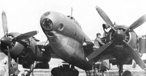 ki-74 picture5.jpg46.7 KB · Views: 172
 ki-74 picture4.jpg49.1 KB · Views: 165
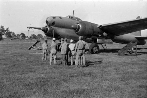 Ki-74 picture3.jpg70.8 KB · Views: 138
 Ki-74 picture2.jpg73.5 KB · Views: 696
 Ki-74 picture 1.jpg85 KB · Views: 726
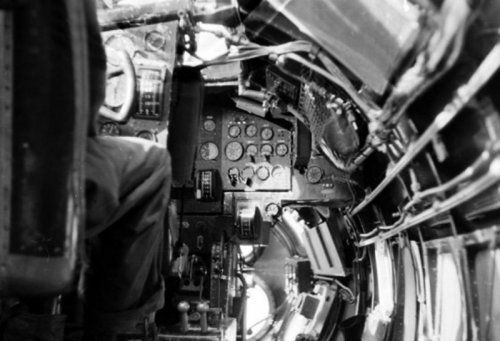 KI-74_COCKPIT_3.jpg199.7 KB · Views: 765
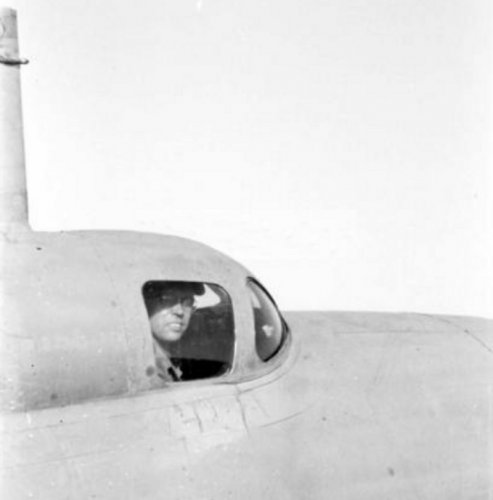 KI-74_COCKPIT_2.jpg131.9 KB · Views: 809
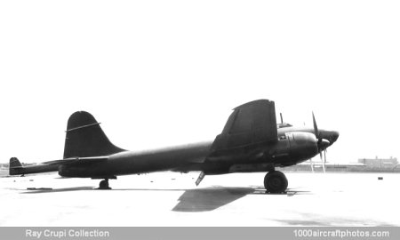


")