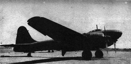
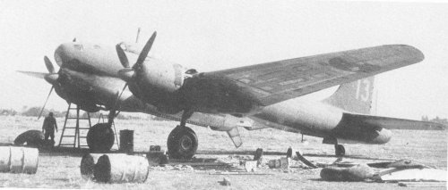
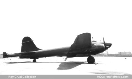
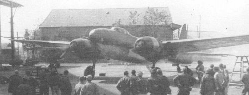
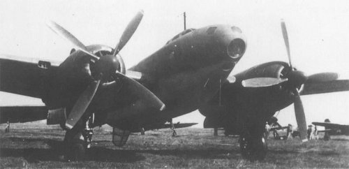
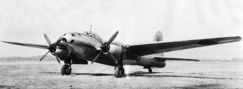
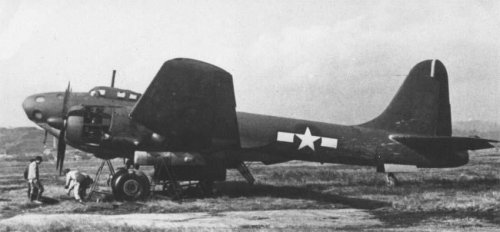
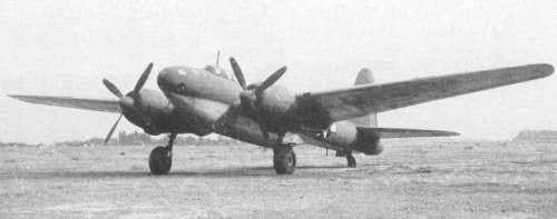
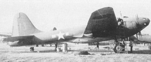
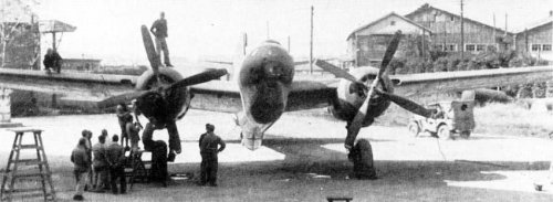
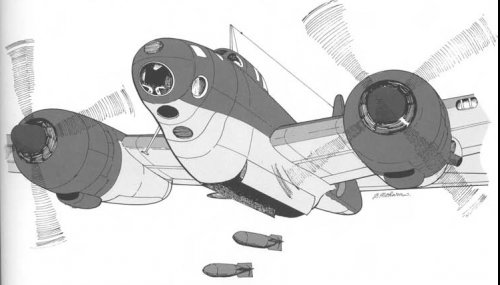
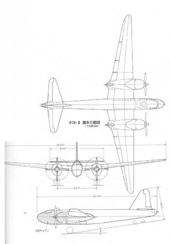
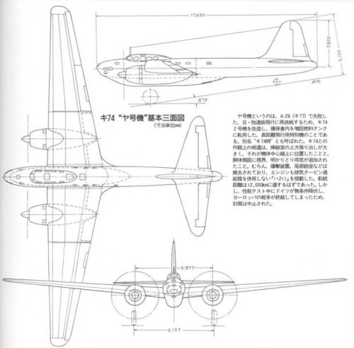
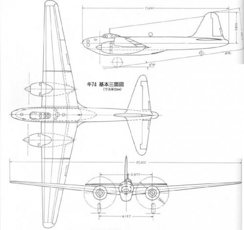
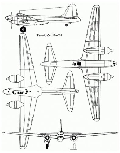
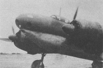
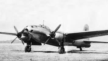
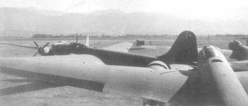
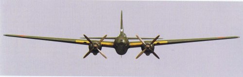
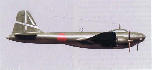
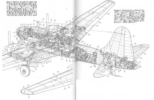
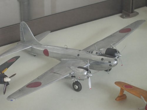
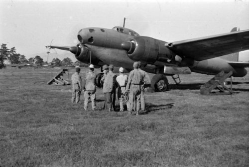
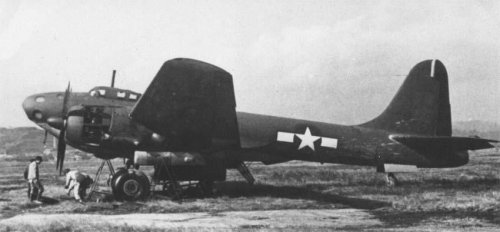
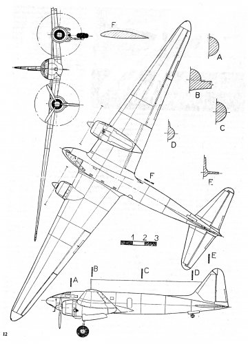
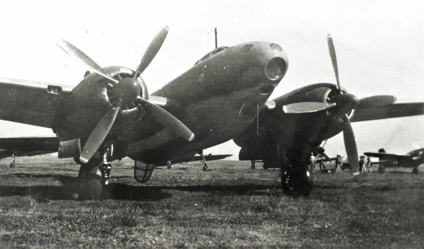
Tachikawa Ki-74 and it's unbuilt variants

blackkite

Don't laugh, don't cry, don't even curse, but.....
Joined
31 May 2007
Messages
9,515
Reaction score
9,661
Hi!
 

Attachments

  • KI-74_COCKPIT.jpg
    KI-74_COCKPIT.jpg
    137.1 KB · Views: 924
  • ki-74 picture5.jpg
    ki-74 picture5.jpg
    46.7 KB · Views: 229
  • ki-74 picture4.jpg
    ki-74 picture4.jpg
    49.1 KB · Views: 216
  • Ki-74 picture3.jpg
    Ki-74 picture3.jpg
    70.8 KB · Views: 183
  • Ki-74 picture2.jpg
    Ki-74 picture2.jpg
    73.5 KB · Views: 737
  • Ki-74 picture 1.jpg
    Ki-74 picture 1.jpg
    85 KB · Views: 770
  • KI-74_COCKPIT_3.jpg
    KI-74_COCKPIT_3.jpg
    199.7 KB · Views: 812
  • KI-74_COCKPIT_2.jpg
    KI-74_COCKPIT_2.jpg
    131.9 KB · Views: 852
Hi next pictures!
 

Attachments

  • Ki-74 picture13.jpg
    Ki-74 picture13.jpg
    26.1 KB · Views: 160
  • Ki-74 picture12.jpg
    Ki-74 picture12.jpg
    37 KB · Views: 153
  • ki-74 picture11.jpg
    ki-74 picture11.jpg
    35.8 KB · Views: 167
  • ki-74 picture10.jpg
    ki-74 picture10.jpg
    36.3 KB · Views: 167
  • ki-74 picture9.jpg
    ki-74 picture9.jpg
    37.7 KB · Views: 152
  • ki-74 picture8.jpg
    ki-74 picture8.jpg
    41.1 KB · Views: 150
  • ki-74 picture7.jpg
    ki-74 picture7.jpg
    39.9 KB · Views: 145
  • ki-74 picture6.jpg
    ki-74 picture6.jpg
    46.1 KB · Views: 170
And more pictures.
 

Attachments

  • KI-74 PIC2.jpg
    KI-74 PIC2.jpg
    141.1 KB · Views: 250
  • KI-74 Ⅱ.jpg
    KI-74 Ⅱ.jpg
    52.4 KB · Views: 265
  • Ki-74 Yago.jpg
    Ki-74 Yago.jpg
    56.5 KB · Views: 261
  • KI-74 3 SIDE VIEW.jpg
    KI-74 3 SIDE VIEW.jpg
    75.9 KB · Views: 251
  • ki-74_3-side.jpg
    ki-74_3-side.jpg
    141.8 KB · Views: 221
  • Ki-74 picture16.jpg
    Ki-74 picture16.jpg
    14.7 KB · Views: 187
  • ki-74 picture15.jpg
    ki-74 picture15.jpg
    9.9 KB · Views: 172
  • Ki-74 picture14.jpg
    Ki-74 picture14.jpg
    23.6 KB · Views: 160
More.
 

Attachments

  • Tachikawa_Ki-74-021.jpg
    Tachikawa_Ki-74-021.jpg
    95.8 KB · Views: 175
  • Tachikawa_Ki-74-04.jpg
    Tachikawa_Ki-74-04.jpg
    109.8 KB · Views: 230
  • Tachikawa_Ki-74-101.jpg
    Tachikawa_Ki-74-101.jpg
    219.1 KB · Views: 231
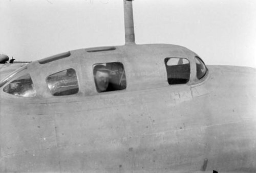
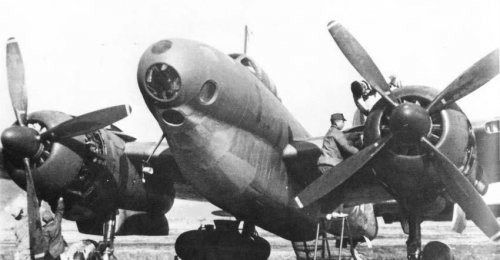
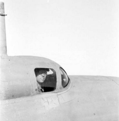
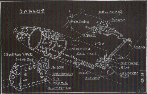
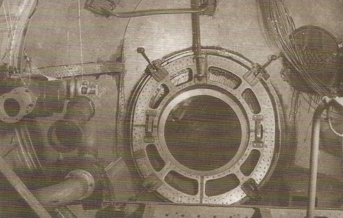
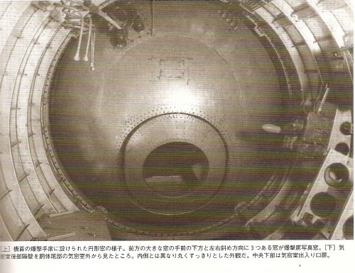
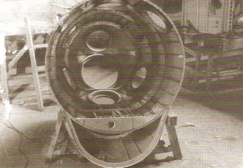
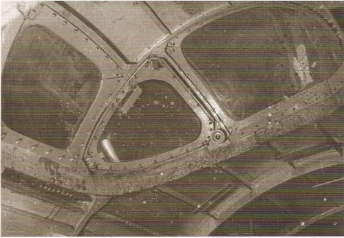
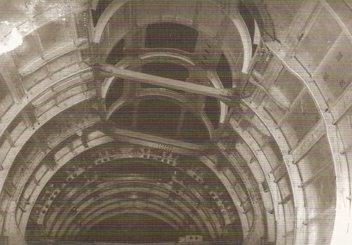
Hi! Cockpit structure taken from the nose and front wind shield.
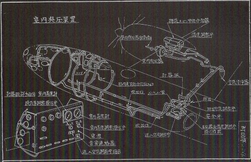
You can see offset wind shield and reinforcement bar to withstand cockpit inner pressure in the first picture.
Cabin pressurising air was intercooler cooling air (after cooling hot air).

http://en.wikipedia.org/wiki/Tachikawa_Ki-74
 

Attachments

  • tachikawa ki-74 model.jpg
    tachikawa ki-74 model.jpg
    303.7 KB · Views: 258
  • cabin pressurizing system.jpg
    cabin pressurizing system.jpg
    933 KB · Views: 206
  • after pressure bulkhead entrance door.jpg
    after pressure bulkhead entrance door.jpg
    588.2 KB · Views: 173
  • after pressure tight bulk head and entrande.jpg
    after pressure tight bulk head and entrande.jpg
    725.2 KB · Views: 162
  • nose structure.jpg
    nose structure.jpg
    688.6 KB · Views: 163
  • front wind shield.jpg
    front wind shield.jpg
    978.2 KB · Views: 173
  • cockpit structure taken from the nose.jpg
    cockpit structure taken from the nose.jpg
    985.7 KB · Views: 180
Hi Alcides san! Thank you for your attention. I will give you some more information about Ki-74. Please wait.
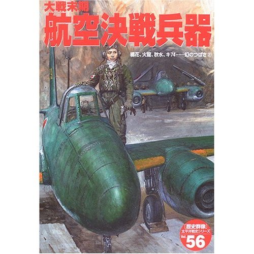
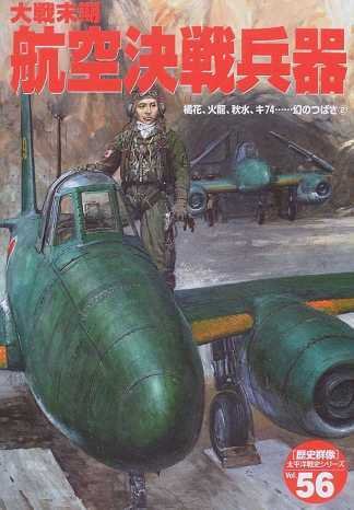
Source : Gakken "大戦末期 航空決戦兵器 (Late war aerial battle weapons)" ISBN4-05-604536-4
I think that the technology which applied to the Ki-74 was very useful for Fugaku design at the day.
Nakajima asked Tachikawa to deliver pressurized cabin technology for Ki-87Ⅱdesign.
 

Attachments

  • 510D02VCQ4L__SS500_.jpg
    510D02VCQ4L__SS500_.jpg
    55.5 KB · Views: 173
  • remote control tail turret.jpg
    remote control tail turret.jpg
    900.1 KB · Views: 177
  • No.4 aircraft turbo charger.jpg
    No.4 aircraft turbo charger.jpg
    1 MB · Views: 219
  • Ki-74 general arrangement.jpg
    Ki-74 general arrangement.jpg
    206.7 KB · Views: 231
  • 3.jpg
    3.jpg
    87.4 KB · Views: 211
  • Tachikawa_Ki-74-03.jpg
    Tachikawa_Ki-74-03.jpg
    212.6 KB · Views: 163
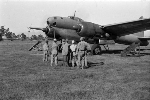
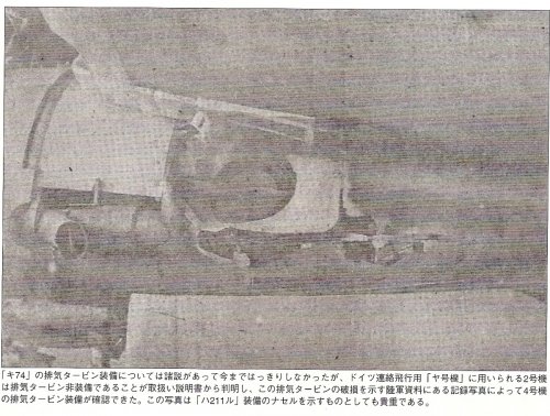
We can see turbo charger exhaust gas outlet and turbo charger bypass exhaust gas outlet in these pictures.
 

Attachments

  • Ki-74 picture3.jpg
    Ki-74 picture3.jpg
    70.8 KB · Views: 184
  • ki-74 picture9.jpg
    ki-74 picture9.jpg
    37.7 KB · Views: 204
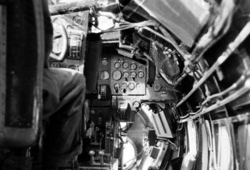
Great pictures Balckkite-san! I believe that picture 3 of your first post is the only known photograph of the finished Ki-74 cockpit.
 
Fascinating collection of photos — some quite rare — of an ugly but so fascinating type! Thanks a lot for this treasure.
 
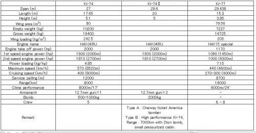
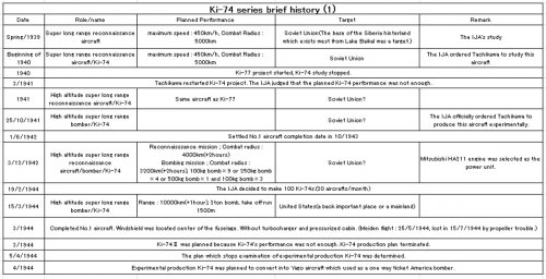
Hi! Ki-74 brief history(1/2).
 

Attachments

  • ki-77_draw.jpg
    ki-77_draw.jpg
    775.3 KB · Views: 222
  • ki-77_draw.jpg
    ki-77_draw.jpg
    956.3 KB · Views: 218
  • Ki-74_and_Ki-77.jpg
    Ki-74_and_Ki-77.jpg
    218.7 KB · Views: 192
  • Ki-74_brief_history_(1).jpg
    Ki-74_brief_history_(1).jpg
    253.6 KB · Views: 220
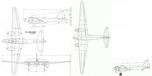
Hi! Ki-74 and Ki-77.(Same scale)
 

Attachments

  • Ki-74_and_Ki-77.jpg
    Ki-74_and_Ki-77.jpg
    163.3 KB · Views: 264
Hi,


the Tachikawa Ki-74 in detail for front section.


http://deuxiemeguerremondia.forumactif.com/t4140p30-quizz-cet-avion-a-trouver
 

Attachments

  • Ki-74.jpg
    Ki-74.jpg
    58.2 KB · Views: 212
Thanks a lot my dear hesham.
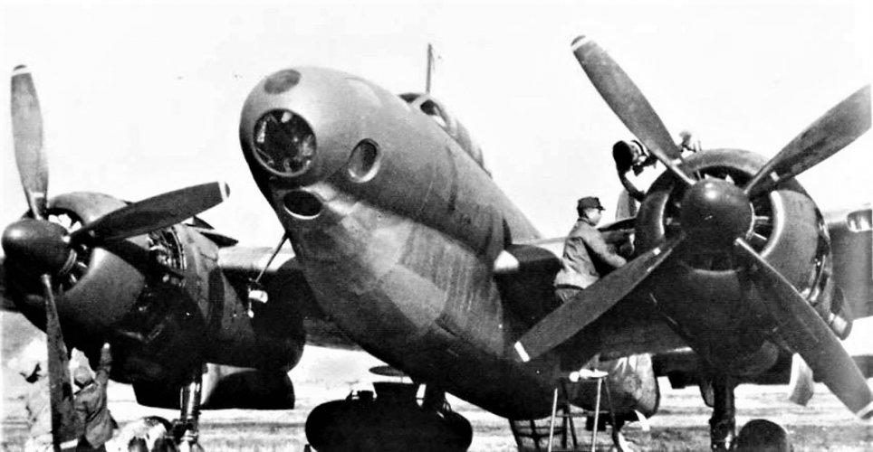
Ki-74's engine was turbo charged Nakajima HA-211ru Homare with forced cooling fan. ;)
Also Ki-74 had a pressurized cabin and remote controled tail turret. Ki-74 was a very advanced aircraft in Japan at the day.
Nakajima aircraft asked Tachikawa to deliver pressurized cabin technology for Fugaku bomber.
I imagine that Nakajima also asked Tachikawa to deliver remote control turret technology for Fugaku bomber,too.
 

Attachments

  • cabin pressurizing system.jpg
    cabin pressurizing system.jpg
    933 KB · Views: 159
  • remote control tail turret.jpg
    remote control tail turret.jpg
    900.1 KB · Views: 163
Oh engines are running. :eek: Tail shape looks like B-17.
 
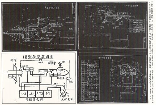
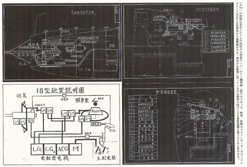
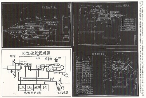
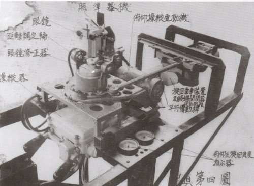
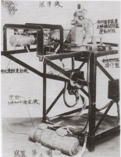
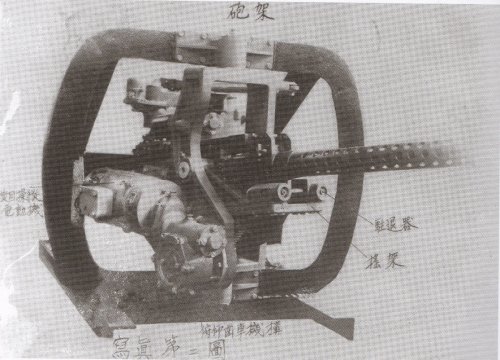
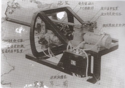
A sight and shooting of a tail remote machine gun were Leonard system through a self synchronizing motor.
ACG : AC generator?
SM : Self synchronizing motor?
M : Motor?
CM : Charge motor?
LG : Some kind of generator?
LM : Some kind of electric equipment?
Someone please help me. :-[

砲架 : Saddle and body、照準架 : Sighter body、照準器 : Sight、発射電磁石 : Firing Electromagnet、引鉄 : Trigger、主配電盤 : Main Switchboard、継電器 : Rejay、発射 : Firing、運転 : Operation、操縦器 : Controls、修正装置 : Compensator

Perhaps
SM1 : Turning control motor
SM2 : Turning control motor
SM3 : Elevation control motor
SM4 : Elevation control motor
LM1 : Turning movement limitation circuit breaker
LM2 : Turning angle transmitter
LM3 : Elevation movement limitation circuit breaker
LM4 : Elevation angle transmitter
LG1,LG2 : ?
 

Attachments

  • remote control tail turret.jpg
    remote control tail turret.jpg
    900.1 KB · Views: 395
LM could stand for linear motor. Why would the abbreviations be in English? ???
 
Winston said:
LM could stand for linear motor. Why would the abbreviations be in English? ???

Perhaps because Japanese didn't have the required words and once established in the Japanese industry, the abbreviations just followed on?
 
Kadija_Man said:
Winston said:
LM could stand for linear motor. Why would the abbreviations be in English? ???

Perhaps because Japanese didn't have the required words and once established in the Japanese industry, the abbreviations just followed on?
Good guess! Thanks.
I tried to translate these Japanese Kanji into English.

Source : ISBN4-05-604536-4 ”The Pacific War last years Air decisive battle weapon” Gakken, 15/11/2006

寫眞第一圖 : No.1 picture
砲架 : Saddle and body、發射電磁石: Firing Electromagnet、平行傅動桿 : Parallel transmission rod、旋回歯車装置 : Turning gear、旋回角度発信器 : Turning angle transmitter、旋回操縦電動機 : Turning motor、俯仰角度発信器 : angle of elevation transmitter、装填電動機 : Charging motor、装填用歯車装置 Charging geae、砲側接續筐 : Gun side connection steel case、

寫眞第二圖 : No.2 picture
駐退器 : Recoil brake、揺架 : Cradle、俯仰歯車機構: Elevation gear mechanism、旋回俯仰操縦電動機 Turning Elevation control motor

寫眞第三圖 : No.3 picture
俯仰歯車装置及運動制限開閉器 : Elevation gear and movement limitation circuit breaker、操作盤 : Control panel、旋回操縦電動機 : Turning control motor、電動発電機 : Electric drive generator

寫眞第四圖 : No.4 picture
照準機 : Sight、俯仰操縦電動機 : Elevation control motor、旋回歯車装置及運動制限開閉器 : Turning gear and movement limitation circuit breaker 、平行傅動桿: Parallel transmission rod、俯仰及旋回角度指示器 : Elevation angle and turning angle indicator、眼鏡 : Spectacles、距離調定輪 : Distance settlement ring?、眼鏡修正器 : Spectacles compensator、操縦器 : Controls
 

Attachments

  • 02718242_1.jpg
    02718242_1.jpg
    20.1 KB · Views: 126
  • Sight pic1 (2).jpg
    Sight pic1 (2).jpg
    435.6 KB · Views: 190
  • Sight pic1 (1).jpg
    Sight pic1 (1).jpg
    1.2 MB · Views: 210
  • Tail turret pic2.jpg
    Tail turret pic2.jpg
    673.5 KB · Views: 222
  • Tail turret pic1.jpg
    Tail turret pic1.jpg
    661.6 KB · Views: 261
Hi!
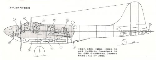
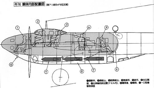
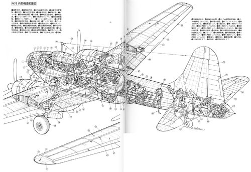
1. Bomber seat, 2. Bombing controller, 3. Ten-type bombing sight, 4. Bomber seat switchboard, 5. Astronomical observation window, 6. Small aerial camera
7. Bomber pillow, 8. Bomber seat, 9. Pitot tube, 10. Autopilot, 11. Sextant, 12. Cockpit main instrument panel, 13. Pilot seat, 14. Engine control lever
15. Rudder operation handle, 16. Cockpit switchboard, 17. Fuel cock control lever, 18. Engine control lever, 19. Main switchboard, 20. Vice pilot instrument panel
21. Co-pilot seat, 22. Antenna support, 23. Antenna, 24. Tail gun gun sight, 25. Crew exit, 26. Oil storage tank, 27. Radio operator desk, 28. Long-distance radio
29. Short-distance radio, 30. Frame type antenna, 31. Bomb bay door, 32. Direction detector receiver, 33. Pressurizer operation panel,
34. Pressure chamber rear end door, 35. Passenger doorway, 36. Bomb bay open / close motor, 37. Oxygen cylinder, 38. Automatic aerial camera,
39. Hanging antenna twine, 40. Hanging antenna post, 41. Tail wheel, 42. Tail leg cushion, 43. Tail wheel storage position, 44.12.7mm machine gun magazine,
45.12.7 mm machine gun (Ho103), 46. Inter cooler, 47. air filter, 48. Third fuel tank, 49. Lubricating oil tank, 50. Main wing girder, 51. First fuel tank inlet,
52. Second fuel tank inlet, 53. Third fuel tank inlet, 54. Auxiliary injection tank
55. Second fuel tank, 56. Lubricating oil tank inlet, 57. Main wheel storage position, 58. Main leg storage position, 59. Main wheel,
60. Inner and outer wing main girder fittings 61. Aileron correction tab, 62. Flap, 63. Inner aileron, 64. Outer aileron, 65. Fourth fuel tank,
66. Forth fuel tank inlet, 67. Fifth fuel tank, 68. Fifth fuel tank inlet, 69. Wing tip light 70. Cascade light, 71. Wing tip cover, 72. Rudder
73. Rudder correction tab, 74. Elevator, 75. Elevator correction tab
ki74-2.jpg
 
Last edited:
Of the 16 prototypes constructed, were any of them the Ki-74-II otsu? This one had a payload of 2000 kg
 
Ki 74-II
A long-range bomber type that was developed in April 1944. This machine was also called "Ya-Go." The scale of the aircraft was expanded to a total length of 20. 0 m, a total width of 29. 6 m, and a total height of 5. 5 m, and the engine became the Mitsubishi "Ha 211 Le". The fuselage has also been redesigned, the pressurized cabin became only at the nose part. The cockpit shifted to the front, smoothly connected to the fuselage, resembling a normal double-seat bomber. There are 7 passengers. Due to the work delay caused by the air raid and the evacuation, only the mockup was produced and the war ended.

Ki 74-Ⅱ Type A(Ko)

A mainland US bombing plane with an emphasis on long range cruising performance. The number of crews was reduced to three, and the total fuel capacity was increased to 12,000 liters by using only two 500 kg bombs. The cruising range was planned to be 8,000 km, and it was supposed to make a one-way attack against the mainland US. Completion of the first prototype was scheduled for August 1944.

Ki 74-Ⅱ Type B(Otsu)
A type that emphasizes the amount of bombs loaded. The cruising range is inferior to the Type A, but it was possible to carry bombs up to 2,000 kg. The first prototype was scheduled for completion in October 1944.
 

Attachments

  • ki-74.png
    ki-74.png
    712.4 KB · Views: 63
Last edited:
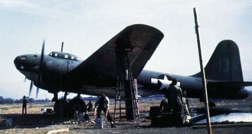
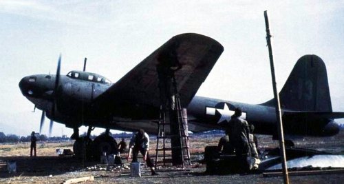
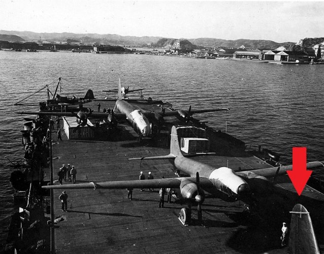
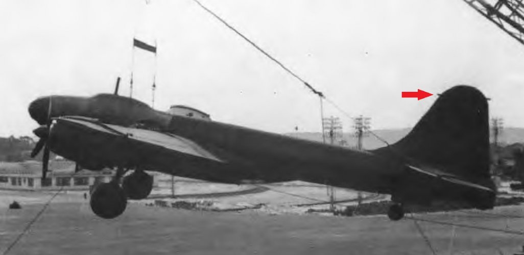
Using the picture below (from another thread), I tried to solve the mistery of the unknown aircraft aboard the USS Bogue in 1945. Looking at the rudders of all the multi-engine planes of similar size, it seems to me that the only one that has a similar rudder is the Ki-74, so two of them were on the aircraft carrier.
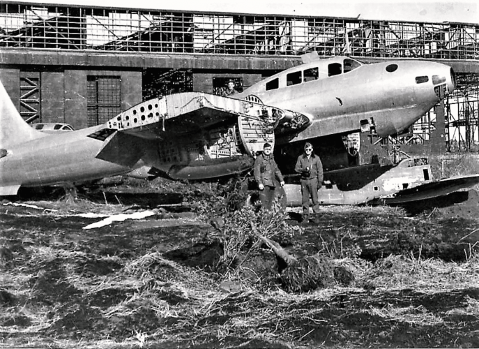
At least a dozen of Ki-74 were built, 4 where found by the Americans, 2 in flyable conditions, according to a document cited by Robert Mikesh in its "Broken Wings of the Samurai. The Destruction of the Japanese Airforce", 2015, p. 110. So it could be that a couple was transported to the USA. It was usual to ship more that one "special" aircraft of the same type, for example on the USS Barnes there were 4 D4Y4, 2-3 J8M1, 2 J5N1.
Maybe the guy who took the pictures didn't also take a picture of the plane closest to the USS Bogue island because it was similar to the one that appears with the G8N1 Renzan.
What do you think?

USS-Bogue-carring-captured-Japanese.jpg

ScreenHunter 1381.jpg

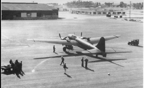
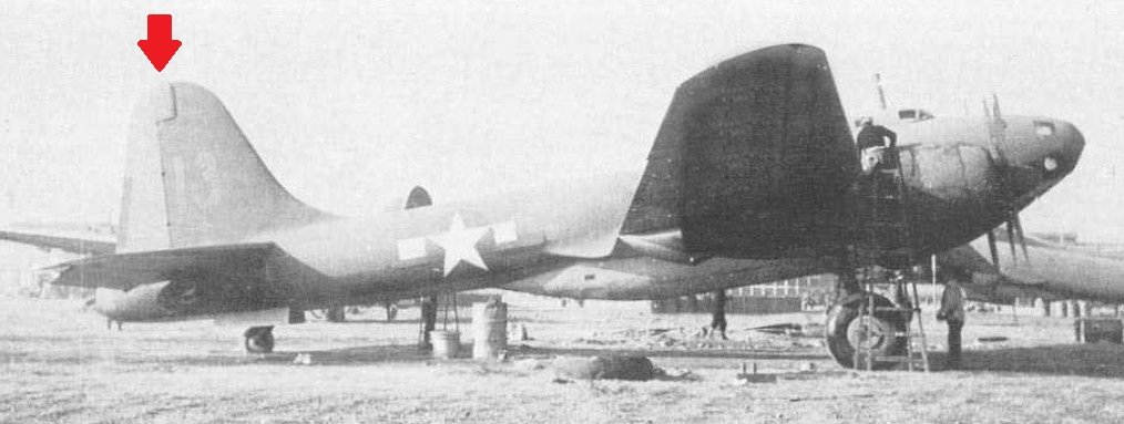
EDIT: In the following picture, taken from the same book, p. 130 (caption"... this Tachikawa Ki-74 “Patsy” is being offloaded at Newark, New Jersey"), the "rudder locking system" is in the same position of the unknown aircraft (the Ki-74 near to the Renzan has a larger locking and positioned in a lower position).

Ki-74 in USA.jpg

In the same book, pages 141-142, a list of the Japanese aircraft in the USA quotes two Ki-74 with Air Technical Intelligence Number T2-2208 and T2-2209. So maybe the mistery is solved... :D
 
Last edited:
Thanks! Amazing❣️
 
Last edited:
Using the picture below (from another thread), I tried to solve the mistery of the unknown aircraft aboard the USS Bogue in 1945. Looking at the rudders of all the multi-engine planes of similar size, it seems to me that the only one that has a similar rudder is the Ki-74, so two of them were on the aircraft carrier....
Replaying to my own post:

According to the book "War prizes" (Phil Butler, Midland Publishing, 2000 page 247) these were the Ki-74s brought to the USA after the war (the same FE numbers reported by blackite in post #25):

Tachikawa Ki 74 'Patsy'. Army Experimental High-Altitude Long-Range Bomber. Twin-engined high-altitude long-range reconnaissance bomber. Only 16 of the type were made. Two of these aircraft were surrendered at the Tachikawa factory and two at the IJAAF Test Bureau at Fussa (Yokota). All four aircraft were included in the 10th March 1946 list.
FE-2206/T2-2206. It was in storage at Atlantic Overseas Air Materiel Center (AOAMC) Newark on 1st August 1946, but had been assigned for disposal.
FE-2207/T2-2207. It was in storage at Middletown on 1st August 1946. It was listed for transfer to the Air Museum on 18th September 1946. No further record.
FE-2208/T2-2208. It was in storage at AOAMC, Newark, on 1st August 1946, but was assigned for disposal.
FE-22091/T2-2209. It was in storage at AOAMC, Newark, on 1st August 1946, but was assigned for disposal.

A couple of notes from the same book to understand the "10th March 1946 list":
Page 161: Foreign Equipment was at first evaluated by the Foreign Equipment Unit of the Technical Staff within the Engineering Division. Later, after the formation of the Technical Data Laboratory in December 1942, came the Evaluation Branch of the Technical Data Laboratory, giving rise to the 'EB-' series of numbers. The Foreign Equipment Unit then became part of the Evaluation Branch, which was in turn one of the six branches of the Technical Data Laboratory. The Technical Data Laboratory's tasks included “Procurement, evaluation and dissemination of technical information on foreign aircraft and aeronautical equipment, particularly enemy aircraft and equipment, of technical or military interest to the Engineering Division and American manufacturers producing AAF materiel”. Later the Evaluation Branch identities were changed to 'FE-' for 'Foreign Equipment', presaging the formation of a Foreign Equipment Branch in April 1945 as one of Evaluation Branch's successor organisations (the Flight Data Branch being the other). Finally, in July 1945, came a re-organisation in which the Technical Data Laboratory became part of 'T-2 Intelligence' within the organisational structure, with other T designators indicating Personnel, Engineering, Administration and other functions. By November 1945, 'T-2' was transferred to a new Collection Division, under the command of Harold Watson, charged with the collection and assessment of equipment and technical information recovered from Germany, Japan and other sources. This Division remained in being until its task was completed in April 1947.

Page 207: FE/T2 markings. These markings were used to identify Axis aircraft evaluated by the USAAF at Wright Field and other Air Force test establishments. The logic behind the allocation of the individual aircraft identity numbers is not known. It is evident that the first main series, starting at 100, applied to single seater fighter types and that a certain commonality of type or aircraft duty applied to other series of numbers. However, neither the basic logic nor a complete list of allocations has been traced in documented form. The most complete source of the numbers is the list of “German Aircraft available for study by Industry” originally published on 10th March 1946, together with it various updates [It includes also Italian and Japanese types].

(This script was a previous "EDIT 2" part of my previous post #27, I preferred to make a new post to make the thread more readable and to have an update in the forum so others can read it)

 
Back
Top Bottom