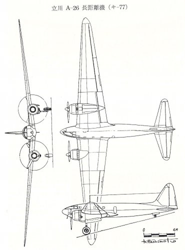
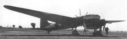
Hi! The Tachikawa A-26 Long-distance plane(Ki-77).
Wing span:29.437m, Overall length:15.3m, Height:3.85m(ground position), Wing Area:79.56m2, Empty weight:7,237kg, MTOW:16,725kg, Max Speed:440km/h(4,600m), Range;18,000km, Service ceiling:8,700m, Engine:Nakajima HA115 special type(1,170hp in take off).
A-26 marked non stop 16,435km flight in Manshu(1944/7/2 to 7/4). Flight time:57hours12minutes, Average speed:288.2km/h, Residual fuel after flight:800L.
If she used all fuel, she could fly 18,000km.
Source:My No.2 bible.
The Ki-77 was a twin-engine research prototype for long-distance flight, of which only two were built, with development costs shared between the Imperial Japanese Army and the Asahi Shimbun Company, and development and design handled by Tachikawa Aircraft and the University of Tokyo's Aviation Research Institute. Nicknamed the A-26, the "A" stands for Asahi, and the "26" stands for 2600 years in the Imperial calendar.
The first aircraft set an unofficial world record for circling the Xinjing Airfield (now Changchun) in 1944, but the second aircraft was lost over the Indian Ocean after taking off from Singapore airport on a connecting flight to Germany in 1943.
Development history
The Asahi Shimbun Company planned a goodwill flight from Tokyo to New York to commemorate the 2600th anniversary of the founding of the Japanese Empire in 1940 (Showa 15), and ordered the development of the aircraft to be carried out by the Tokyo Imperial University Aviation Research Institute. The flight plan members included Iinuma Masaaki and Tsukagoshi Kenji, who had been pilots on the Kamikaze. Development of the aircraft was once halted due to the deterioration of Japan-US relations, but development was resumed at the direction of the military, which had taken notice of the aircraft's exceptional long-distance flight performance (capable of flying to the US mainland). This was for the development of the long-range strategic bomber Ki-74 planned by the Japanese Army, and the main parts, except for the fuselage such as the wings and tail, were designed to be reusable as they were. Two aircraft were completed in 1942 (Showa 17). The first flight was successful on November 18th, when test pilots Kamata Zenjiro and Nagatomo Shigemitsu made their first successful flight.
Reflecting on the failure of project management during the development of the KOKENKI (project management by researchers and detailed design considering construction methods were unreasonable) and the speed was too slow, development was led by aircraft manufacturers to make a realistic and practical aircraft. When selecting the manufacturer, Tachikawa, which had more spare capacity than other manufacturers, was selected. Another reason is thought to be that it was close to the Army's testing grounds.
Design
As a new technology, the fuselage was planned to be pressurized, but due to many technical difficulties, the idea was abandoned. The aircraft has a beautiful streamlined shape like the Type 100 Reconnaissance Aircraft. The dorsal fins, which were added to improve straight-line performance without compromising maneuverability, make the line from the fuselage to the vertical tail look beautiful.
The main wings use integral tanks, the first of their kind made in Japan. In order to develop a construction method, members of the First Wing Assembly Section investigated and studied the assembly of the G4M at Mitsubishi's Oe (Nagoya) during the war and returned to Tachikawa. However, the first aircraft continued to leak fuel, and about 250 kg of repair material was used. Taking this into consideration, the second aircraft significantly revised the construction method, including the number of outer panels stacked at once and the method of sealing, and the fuel leaks were almost completely stopped. The person who came up with this construction method was a former joiner. About 460 people were put into the difficult task of manufacturing the main wings.
There was no room for new engine development, and Nakajima Ha-115 (Navy name "Sakae") series engines were used with only a change in the reduction ratio. The shape of the engine nacelles was too small, making it difficult to cool the engine, and the ignition plug cords were plagued by burnout, so the first aircraft was modified with an oil cooler and other modifications before the record flight.
Long-distance flight
In 1943 (Showa 18), the Ki-77 was to be used for the wartime contact flight (Se flight) to Germany, where sea traffic was cut off during World War II. The second aircraft was selected because it was considered to be better than the first. In order not to provoke the Soviet Union, which was neutral with Japan, it was decided to take a southern detour route via Syōnan (Singapore) for this flight to Germany. On June 30, the second aircraft, carrying pilot Nagatomo and five other Asahi Shimbun Aviation Department crew members and three army officers, took off from Fussa Airfield, and on July 7, it headed straight for German territory from Syōnan, a stopover point, but went missing on the way. There is no record of it being shot down by the Allied forces, so the reason for its disappearance is completely unknown. There is footage of it taking off from the stopover point.
On July 2, 1944, the first aircraft, with Captain Toshio Omata, pilot Hisayoshi Tanaka and six others on board, flew 16,435 km in a triangular course from Xinjing to Harbin to Baichengzi in 57 hours and 12 minutes, setting a world record for circumnavigation distance and an international speed record. However, since this was during wartime, the record was not officially recognized by the Fédération Aeronautics Internationale (FAI).
At the end of the war, it was abandoned at Kofu Airfield and was in no condition to fly, but it was repaired by order of the US military and loaded onto an aircraft carrier at Oppama. Engineer Jiro Tanaka, who would later work for Prince Motors, was in charge of repairs and maintenance. Engineer Tamotsu Toyama was in charge of transportation (the famous photo of it flying with Mt. Fuji in the background was taken by Engineer Tamotsu Toyama from an escort aircraft at this time). According to official documents, the aircraft (No. 1) was damaged in a storm during transportation. It was brought to a naval base in Pennsylvania in a wrecked state along with the Ki-74 that was sent at the same time around 1946. It was scrapped around 1949.
No. 1 had been left abandoned for a while before its record flight, so it had been repaired twice.
The First Wing Assembly Section continued to manufacture the Ki-36, Ki-74, Ki-106, etc. until the end of the war, and was disbanded at the end of the war. Many of the craftsmen returned to their original jobs as carpenters, joiners, and furniture makers after the war. Currently, documents remain at the National Museum of Nature and Science and the Museum of Aeronautical Sciences in Chiba Prefecture, and there is a book called "Tragic Wings A-26" (by Kazuya Fukumoto) based on the design documents of Professor Hidemasa Kimura. In addition, the house of a person who belonged to the First Wing Assembly Section has the process diagrams of the main wing at that time (including diagrams of the layout of the spars and ribs and the layout of the main landing gear structure).
A beautiful US military aircraft flying low over Mount Fuji?
No, it's the final, majestic sight of a Tachikawa Aircraft Ki-77, a world record holder for long-distance flight that was taken prisoner by the US military when Japan was defeated in August 1945. This is the title photo for an article contributed to the May 1960 issue of Fuji Precision News, the company's in-house magazine, by Toyama Tamotsu, who was the company's managing director at the time.
"TWing of tragedy" includes a full paper on the A-26's basic design by Professor Kimura Hidemasa of the Department of Aeronautical Engineering, Faculty of Engineering, Tokyo Imperial University, who was the A-26's chief designer. The following is a summary of the description of the main wing:
This B-series composite laminar flow airfoil, designed by Aeronautical Research Institute member Fukatsu Ryozo, has the unique feature of maintaining a constant maximum camber value of 24.88% of the maximum wing thickness, regardless of wing thickness.
With a linearly tapered wing like the A-26's, the wing thickness decreases from the center to the wingtip, and the maximum camber value of each cross section decreases proportionally. If the maximum camber value were constant, it would be easy to determine the maximum camber value that would minimize airfoil resistance at a design lift coefficient of 0.6. However, when the maximum camber varies along the wing span, the process of determining the maximum camber value that minimizes airfoil resistance is complex and difficult.
The final designs decided upon were B16 for the center section of the wing (maximum thickness 16%, maximum camber 4%) and B9 for the tip section (maximum thickness 9%, maximum camber 2.25%).
For each section, the positions of maximum thickness and maximum camber were at 45% of the chord.
"TWing of tragedy" includes a full paper on the A-26's basic design by Professor Kimura Hidemasa of the Department of Aeronautical Engineering, Faculty of Engineering, Tokyo Imperial University, who was the A-26's chief designer. The following is a summary of the description of the main wing:
This B-series composite laminar flow airfoil, designed by Aeronautical Research Institute member Fukatsu Ryozo, has the unique feature of maintaining a constant maximum camber value of 24.88% of the maximum wing thickness, regardless of wing thickness.
With a linearly tapered wing like the A-26's, the wing thickness decreases from the center to the wingtip, and the maximum camber value of each cross section decreases proportionally. If the maximum camber value were constant, it would be easy to determine the maximum camber value that would minimize airfoil resistance at a design lift coefficient of 0.6. However, when the maximum camber varies along the wing span, the process of determining the maximum camber value that minimizes airfoil resistance is complex and difficult.
The final designs decided upon were B16 for the center section of the wing (maximum thickness 16%, maximum camber 4%) and B9 for the tip section (maximum thickness 9%, maximum camber 2.25%).
For each section, the positions of maximum thickness and maximum camber were at 45% of the chord.
Without wanting to spread my science or play straighteners , I would just like to specify that the average curvature line of a wing profile passes through the exact middle of the profile thickness (we talk about the skeleton of the profile), which the red line in the figure does not represent ... (I know well that the art of geometry is to reason just on false figures, but well ... ).
When the Pacific War ended with Japan's defeat, the A26s were evacuated to Kofu Airfield in Yamanashi Prefecture. A few days after the U.S. military entered Japan, Tachikawa Aircraft's Engineer Tamotsu Toyama received an order to "immediately prepare the A26 for flight and airlift them to Oppama Airfield in Yokosuka." Engineer Toyama refused, arguing that the A26 had been abandoned for a long time and were no longer in flight-ready condition. However, the victors were not convinced and responded, "The United States is very interested in the A26, which set a world record for long-range flight, even if it is unofficial. If you continue to refuse to hand it over, the United States is prepared to take strong measures. Are you willing to accept this?" Unable to resist this threat, Engineer Toyama laboriously gathered together a team of mechanics and managed to prepare the first A26 for flight, even replacing the Japanese flag with the U.S. military insignia on its fuselage. The first A26 was airlifted to Oppama Airfield, loaded onto a U.S. aircraft carrier anchored in Yokosuka Port, and sent to the United States for performance testing. There are many theories about the A26's fate. For example, one theory is that the A26 that arrived on the U.S. mainland was scrapped at Wright Field, Ohio, without undergoing sufficient performance testing. After the war, Professor Kimura would visit the U.S. every time he visited, he would investigate the fate of the A26, but he was never able to find out where the actual aircraft was.
However, Professor Kimura, who had written an article about the A26 at the request of a British aviation magazine, received some interesting information about the A26 from Major Mikesh of the United States Air Force in Japan, who had read the article. Major Mikesh had a deep knowledge of Japanese military aircraft during the Pacific War and was very familiar with the A26. According to him, "The aircraft carrier that was heading to the United States loaded with A26 encountered a severe typhoon in the Pacific, and several aircraft moored on the deck were swept away by the high waves. It is possible that the A26 was among them."
Also Asahi newspaper got same information.
In September 1971, 26 years after the end of the Pacific War, Professor Kimura flew nonstop from New York to Tokyo on a Boeing 747SP at the invitation of Boeing. "It was a long wait, but it was a comfortable flight," he told reporters in the VIP room at Tokyo International Airport.
Of the Five Samurai involved in the construction of the YS11, Jiro Horikoshi (second from the left), Takeo Doi (third from the left), and Hidemasa Kimura (far right) are three. On the far left is Eitaro Komabayashi, former head of the Japan Aviation Technology Department. (Photo courtesy of Kakamigahara Aerospace Science Museum)
Attachments
Of the Five Samurai involved in the construction of the YS11, Jiro Horikoshi (second from the ...jpg
The Kawanishi Aircraft TB was a super-large bomber planned by Kawanishi Aircraft for the Imperial Japanese Army. The "TB" in the name was an abbreviation of "Toyou Bakugekiki" (Transoceanic Bomber), and the internal name of the aircraft at Kawanishi Aircraft was "KX9."
Background:
In the summer of 1943, the Cabinet Planning Agency (later the Ministry of Munitions) ordered Kawanishi Aircraft Company to build a large bomber for bombing the US mainland. The Army and Navy were not involved in this order, and the military did not assign a prototype name, but the TB project itself was led by the Navy in collaboration with the Ministry of Munitions. The required performance was similar to that of the Nakajima Aircraft Company's Fugaku, which the Army and Navy were also developing at the time, with a range of 22,222 km and the ability to land in German territory after bombing the US mainland, refuel, and return to Japan.
Kawanishi worked on the design in collaboration with the Tokyo Imperial University Aeronautical Research Institute (KOKEN), with the latter taking the lead in the design. The overall design was handled by Professor Kimura Hidemasa of KOKEN and Kawanishi engineers, the main wing design was handled by Professor Tani Ichiro of KOKEN, and the fuselage and tail were handled by Kawanishi. One month after the start of design, Kawanishi and the Naval Air Technical Arsenal (Kugisho) conducted two wind tunnel tests using a full model, which achieved good results. After determining the external shape and internal structure, the plan was finalized on January 14, 1944. After examining the results of the wind tunnel tests, an explanatory meeting was held for military personnel, mainly the Navy, but the only question from the military was from Staff Officer Genda Minoru regarding the lack of speed, and Kawanishi's design chief Shizuo Kikuhara, who attended the meeting, recalled that he sensed no enthusiasm from the military for the TB.
The TB was repeatedly considered, including the Fugaku, Ki-74, and Ki-91, and from January 1944 the Army and Navy began a final comparison with the Fugaku. As of March of that year, the Navy was promoting the TB, which had potential for engine development, but the Fugaku was ultimately selected and the TB development plan was scrapped.
Incidentally, even before the TB was ordered, in December 1942 the Army had instructed Kawanishi to research a long-range bomber for bombing the US mainland, and wind tunnel testing was completed by January 1943. The key performance requirements for this research were broadly similar to those of the Fugaku and TB.
The TB was planned as a four-engine aircraft using modified existing engines, with a design principle that integrated technologies already in place or likely to be perfected in the future. Unlike the original Fugaku design, which featured six newly developed 5,000 hp engines, the TB would have a smaller bomb load than the Fugaku, but a more solid design.
The engines would be either the Mitsubishi Heavy Industries Ha-43 or the Nakajima Aircraft Ha-45-20, modified with a three-stage supercharger, intercooler, forced-cooling speed-up fan, and a different gear ratio.
The main wing featured a laminar-flow airfoil (LB wing) design, a design developed by Professor Tani to reduce drag. This resulted in a high lift-to-drag ratio of nearly 35 in wind-tunnel tests of the wing alone. The tail was designed with only the minimum area necessary to maintain stability.
The fuselage was designed as slim as possible to reduce drag, and liquid oxygen was released into the aircraft without a pressurized airtight chamber. The main wheels were dual-wheeled, with one of the wheels designed to be jettisoned after takeoff due to lack of storage space, then retrieved and reused. Various measures were considered to shorten the takeoff runway as much as possible, including the use of automatic flaps, solid rockets for takeoff assistance, an electric trolley, and a sloped runway.
Specifications (Planned Values)
Source: "Fugaku [Bomb the US Mainland]" page 451; "The Tale of the Giant Aircraft" pages 322-328.
• Length: 28.0 m
• Wingspan: 52.5 m[27] or 52.4 m[20]
• Wing area: 220.0 m2
• Weight: 26,500 kg
• Standard gross weight: 45,000 kg
• Overload gross weight: 74,000 kg
• Engines: 1,900 hp x 4
• Maximum speed: 600 km/h (at 12,000 m)
• Combat altitude: 12,000 m
• Range: 23,700 km[27] or 22,224 km[28]
• Armament:
4 x 13 mm cannons (1 twin, 2 single)
2,000 kg–6,000 kg bomb load in the bomb bay, up to 15,000 kg under the wings
However, Professor Kimura, who had written an article about the A26 at the request of a British aviation magazine, received some interesting information about the A26 from Major Mikesh of the United States Air Force in Japan, who had read the article. Major Mikesh had a deep knowledge of Japanese military aircraft during the Pacific War and was very familiar with the A26. According to him, "The aircraft carrier that was heading to the United States loaded with A26 encountered a severe typhoon in the Pacific, and several aircraft moored on the deck were swept away by the high waves. It is possible that the A26 was among them."
At this page there are the two images posted by Blackkite in post #6, and a third one of the USS Bouge with four big Japanese aircraft on the deck (from the stern to the bow):
G8N1 "Renzan" (Rita)
Ki-74 (Patsy)
?? (behind the aircraft carrier island in the third picture)
Ki-77 (A-26, Pat)
The caption of the third picture is:
Ray Dunham, AETM2/c, comments: "The Bogue was at anchor in Yokohama Harbor, Tokyo Bay for Christmas,1945. We had taken on some Japanese planes which the photo shows on the flight deck. We left Japan & sailed for San Francisco."
Laurice E. Willoughby, Coxswain, adds: "The photo was taken [...] when the Bogue was entering the San Francisco Bay near the Alameda Naval Air Station." Laurice was a crewman aboard the Bogue until she was placed out of commission in reserve, 30 November 1946 at Tacoma, WA.
Lt. Roy Steinmetz, USN (Ret.), provides the exact date: "8 January 1946 - Arrived Alameda, CA." Lt. Steinmetz was in the Bogue from October 1943 until 28 February 1946.
So it seems like that all the planes arrived in California at the beginning of January 1946. Below the third picture taken from that site.
From this page (taken from "COM 12 - War Diary", Record Group 38 Records of the Office of the Chief of Naval Operations
Series:World War II War Diaries, Other Operational Records and Histories, NAID: 77652087Container ID: Roll A2058 at the national Archives), USS Bogue actually arrived at Alameda on 8 January 1946 (but from an unmarked port of departure). Maybe someone can find a more detailed document on the USA archives.
From the following document "Chronology of USS Bogue (CVE-9)", taken here, the port of departure was Yokosuka, but with an an unknown cargo on board.
EDIT: Robert Mikesh in its "Broken Wings of the Samurai. The Destruction of the Japanese Airforce", 2015, p. 116, states that he located only the USS Barnes inventory of the 45 transported aircraft in the USA, or at least departed from Japan on that ship. He also cites an "unconfirmed report" about some aircraft tossed in the sea during a severe storm encountered by one (or more) of the ship(s) used in the trasport. USS Bogue was the last of the three aircraft carriers transporting Japanese airplanes to the USA, starting from Yokosuka: Barnes (November 16 from Japan), Core (November, day unknown) and Bouge (December 26th), respectively CVE-20, 13 and 9. He confirmed also USS Bogue arrived in Alameda on January 8th of the following year. Most, if not all, of the aircraft on USS Bogue continued the journey with the ship to Newark (NJ) on the East coast, via the Panama Canal.
"TWing of tragedy" includes a full paper on the A-26's basic design by Professor Kimura Hidemasa of the Department of Aeronautical Engineering, Faculty of Engineering, Tokyo Imperial University, who was the A-26's chief designer. The following is a summary of the description of the main wing:
This B-series composite laminar flow airfoil, designed by Aeronautical Research Institute member Fukatsu Ryozo, has the unique feature of maintaining a constant maximum camber value of 24.88% of the maximum wing thickness, regardless of wing thickness.
With a linearly tapered wing like the A-26's, the wing thickness decreases from the center to the wingtip, and the maximum camber value of each cross section decreases proportionally. If the maximum camber value were constant, it would be easy to determine the maximum camber value that would minimize airfoil resistance at a design lift coefficient of 0.6. However, when the maximum camber varies along the wing span, the process of determining the maximum camber value that minimizes airfoil resistance is complex and difficult.
The final designs decided upon were B16 for the center section of the wing (maximum thickness 16%, maximum camber 4%) and B9 for the tip section (maximum thickness 9%, maximum camber 2.25%).
For each section, the positions of maximum thickness and maximum camber were at 45% of the chord.
Requisition and Transport:
After the war, the Imperial Japanese Navy's rocket fighter "Shusui" was seized for technical research. One prototype (No. 403) was transported from Yokosuka to the United States aboard the escort carrier "Barnes."
Exhibition Location:
The transported Shusui (No. 403) is now on display at the Planes of Fame Air Museum in Chino, California, alongside the Navy's local fighter "Raiden."
Other Shusui
Scrapped Aircraft: Another Shusui prototype (No. 81) was also sent to the United States, but was scrapped after investigation.
Source : Japanese wikipedia
FE-154 Tachikawa Ki-77
A low-wing cabin monoplane with twin piston engines and a tail wheel undercarriage, Tachikawa A-26 (Ki-77) No 1
was derived from a design commissioned by the Asahi Shimbun newspaper to break the flight distance record set
by a rival. Due to war preparations nothing came of the intended non-stop flight to Berlin, but the plan was
revived when an Italian plane managed to visit Japan. It was the intention that the 2nd prototype should make
the attempt, but it vanished during the flight, probably shot down by long-range allied fighters. The sole
remaining first prototype of the Tachikawa Ki-77, that in the meantime had been used to set an inland
distance record, was found by US forces at the end of the war at Yamanashi airfield in Japan. Shipped from
Yokosuka, Japan to the USA 16Dec45 on USS Bogue (CVE-9), arriving NAS Alameda, California 8Jan46. T-2 Office
of Air Force Intelligence, Technical Data Laboratory, Air Materiel Command, Wright Field, Dayton, Ohio.
Middletown Air Materiel Area, Middletown, Pennsylvania. Renumbered as T2-154.
This site uses cookies to help personalise content, tailor your experience and to keep you logged in if you register.
By continuing to use this site, you are consenting to our use of cookies.




 , I would just like to specify that the average curvature line of a wing profile passes through the exact middle of the profile thickness (we talk about the skeleton of the profile), which the red line in the figure does not represent ... (I know well that the art of geometry is to reason just on false figures, but well ...


