Any news relating to the future long range AAM development for the PAK-FA (T-50)? I heard recently that the R-172 was canceled leaving just the R-37 in production. The R-37 is too big to be fitted inside the bays of the T-50.
Any news relating to the future long range AAM development for the PAK-FA (T-50)? I heard recently that the R-172 was canceled leaving just the R-37 in production. The R-37 is too big to be fitted inside the bays of the T-50.
Its derivative (RVV-BD - a development of 810?) will fit in the weapon bays of the T-50...
It is an interesting choice - very good ballistic performance and range, but may face limitations in terminal maneuverability.
I've been wondering if the higher diametre of the missile could allow for more advanced or mult-mode seekers which are being developed to hit stealthy targets - but this last bit is just speculation. What is clear is that the missile has plenty of 'room' for development.
It certainly has room for such improvements. Nonetheless it may not need much of maneuverability as its purpose is to hit targets like AWACS or bombers.. which isn't really maneuvereable.
...but if it is your entire BVR armament - is the PAK-FA only supposed to use its two self-defense WVR missiles against fighters? The RVV-BD has to be able to engage maneuvering targets if it is going to be the main BVR weapon.
Well the LEVCONs work as rudders...
Interesting to have that confirmed...
It is also interesting to note how little the elevator is used (with the exception of the very beginning/end of quick high AOA turns it seems the elevator isn't used)...
It is also interesting to see how all of the control surfaces are used as aerodynamic brakes during landing...
Any news relating to the future long range AAM development for the PAK-FA (T-50)? I heard recently that the R-172 was canceled leaving just the R-37 in production. The R-37 is too big to be fitted inside the bays of the T-50.
There is this:
http://saidpvo.livejournal.com/205048.html
http://missiles2go.ru/2013/08/30/новая-зур-рзв-мд-на-макс-2013/
It is billed as a SAM, but I would not be at all surprised if the next generation SRAAM turned out to be very closely related indeed. Here's why:
1. It is designed by Vympel, traditionally associated with air-to-air weapons (including, for example, the R-73).
2. The layout, size and concept are strikingly reminiscent of the British CAMM - a close derivative of ASRAAM.
3. In fact, forum member Mercurius has hinted that Vympel's engineers regard ASRAAM as the short-range missile 'to beat'.
If this isn't actually a sister design to the SRAAM for the T-50, it probably is a at least one of the contenders in the requirement that led (or will lead) to it.
The range estimates would have to be reassessed for an air-launch. It still won't be BVR capable though. Anyway, it is certainly compact enough for the side-bays.
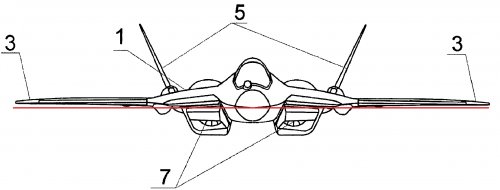
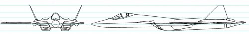
Regarding the frontal view in the patent drawing, is that from 0 AOA or from perpendicular to landing gear plane? I have a feeling its the latter because the tunnel in the drawing isn't flat.
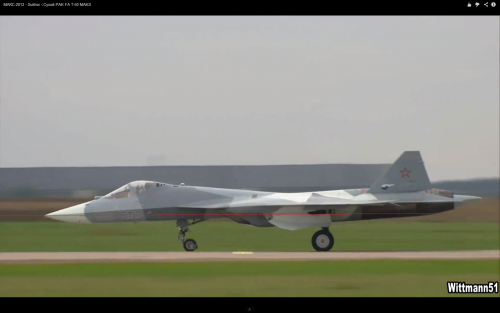
It isn't drawn from the landing gear plane - if you look at the start of the videos you can see it has a nose down attitude - which certainly makes it look like a mean MF...
It isn't drawn from the landing gear plane - if you look at the start of the videos you can see it has a nose down attitude - which certainly makes it look like a mean MF...
It isn't drawn from the landing gear plane - if you look at the start of the videos you can see it has a nose down attitude - which certainly makes it look like a mean MF...
True, but the frontal view drawing from the patent looks like the nose is point down a little. Also, the flat plane between the engine nacelles is angled downwards slightly.
Paralay added these handy horizontal lines to patent drawings. The nozzles do seem to be angled upwards slightly in those views, though it doesn't appear to be as much as I thought it would be from the landing gear plane.
Why would an aircraft have its engine pointed downwards slightly at 0 AOA?
Compressor face is mounted low while the back end is higher(engine is also toed in); it makes the intake duct "straighter" and suffer less from distortions. You could call it semi-S-duct.
Paralay added these handy horizontal lines to patent drawings. The nozzles do seem to be angled upwards slightly in those views, though it doesn't appear to be as much as I thought it would be from the landing gear plane.
Why would an aircraft have its engine pointed downwards slightly at 0 AOA?
You're making the mistake of assuming the stance it has on the ground, or how it's drawn in the drawings, is somehow relative to the AOA it has in flight. Most fighters, at least in flight at subsonic speeds have a slight tail down/nose up attitude in flight.
Having said that, a fan blocker will work well with regard to LO, as the primary purpose is to hide the compressor face. The only thing I don't know, and perhaps some of our LO experts here could chime in on, is how the inlet trunk will attenuate those signals. Does the fan blocker itself accomplish that in much the same sense that an S-Duct possibly does or is the difference negligible? Is there also some sort of LO matching that takes place between the fan blocker and inlet trunk? Are the answers to those questions too far above our pay grade and security clearances?
It's probably futile for me to ask this, but has the Russian Air Force supercruise speed requirement been made public or leaked anywhere?
I've seen supercruise speed claims all over the place for the T-50. This source lists Mach 1.7 to 1.8, (and some people say this is with 117 engines). Piotr Butowski has said in multiple articles that it's Mach 1.3 with 117 engines and Mach 1.6 with Product 30 engines (seems pessimistic). And I think an official Russia-1 TV program listed Mach 2 supercruise and 500 km/h faster than F-22.
Status: as of 27.03.2012 - deystvuetPoshlina: accounted for 6 year from 16.12.2010 to 15.12.2011 [/size]
[/t]
[/t][/t][/q]
(54) Combustion Afterburner Turbojet engines
(57)
AfterBurning Turbojet combustion Chamber Comprises in series in the direction Flow, Front device Arranged with A V-Shaped flame stabilizer and the central body. Within the V-Shaped Placed burners flame stabilizer, and the stabilizer is Made of two Annular Apart segments spaced at A Distance not less than the Maximum Cross-sectional thickness of the central body. The central body Comprises A fixed body with A flat surface on both sides and into contact with the Planar deflectable panel Thickened Rounded in Cross-section and A Tapered Front portion of the output. Wedge-Shaped outlet portion and contacting the flat surface of the body and deflected panels Covered with Radar absorbing Materials. Flat panel and HINGE connection with the casing of the central body are hollow and Made Drive was Done on both sides of A hollow spring . Inside the hollow of each panel fixed swivel Arranged Cylindrical hollow rod, Outer surface on Which Carries Movable landing with the inner surface of the hollow Joint. The ends of each Cylindrical hollow rods Extend Inside the hollow springs, Pylons and through lateral Openings in the wall of the Afterburner Chamber connected with the Cooling air ducts. Swivel joints and Cylindrical rod Provided with two rows of through holes Disposed at an angle to each Other so That the rest undeflected Position Opening the panel rods and joints Coincide with each Other in the direction of the Flow Front and rear row - do not Coincide, and Vice versa When A deflected Position rear panel holes are lined in rows, and Front - not the Same. The Internal cavity of each flat bar on the one Hand, through holes connected to Inside the Chamber of the Afterburner and the Other Side panels in A deflected Position is connected through Matching A hole in the rod and the HINGE connection with the inner cavity of the Cylindrical rod. The Outer surface of each panel swivel Across ITS length is Made Thin -walled screen streamlined shape, forming a cavity between the inner screen and the outer surface of the swivel which is connected with the original undeflected position coinciding front panels through the rows of holes in the rod and pivotally connected to the inner cavity of the cylindrical rod and the Opposite direction from the swivel Edge of each flat panel is in the form of an Ellipse and the Event in both panels panels projection Onto the Plane of the Cross-section represents the Camera screen as A Circle. The Invention Improves the Reliability of the afterburner combustion chamber and reduces the infrared radiation to the rear hemisphere of the engine. 8 ill.
The invention relates to aircraft engine, in particular to the afterburner combustion.
Known afterburner combustion chamber turbojet engine comprising an outer wall, and sequentially in the flow direction, front device arranged with a V-shaped flame stabilizer and the central body inside the V-shaped flame stabilizer placed burners, and the stabilizer made of two ring segments located to the central body in the corresponding cross-sectional semicircle afterburner chamber and spaced apart by a distance not less than the maximum thickness of the cross section of the central body, the central body is fixed to the wall by means of an afterburner streamlined pylon due to the cooling air ducts comprises a stationary housing with flat surfaces on both sides and into contact with the planar deflectable panel thickened rounded in cross-section and a tapered front output portion deflectable its front panel secured to the front side of the case from the central fairing body and connected by a swivel actuator for deflecting them from contacting flat surfaces of the body, wedge-shaped outlet portion and contacting the flat surface of the body and deflected panels covered with radar absorbing materials (see the Russian Patent number 2,258,830, IPC F02K 7 3/10, 13.01.2004 g).
HOWEVER, the presence of the Flow Deviation in the tube panels articulated lever system unwieldy Increases the Total pressure loss in the Afterburner Chamber and, consequently, specific fuel to Increase Consumption as A Whole. Supplying Cooling air through Openings in the walls of the central body plane virtually flat panel off in the deflected condition and thereby reduces the reliability and reduces the effect of reducing the level of infrared radiation to the rear hemisphere of the engine.
The invention is to achieve an optimal combination of reliable performance afterburner, the values of hydraulic losses and reduce the effectiveness of infrared light in the rear hemisphere motor.
Said technical result is achieved in that the afterburning turbojet combustion chamber comprises an outer wall and sequentially in the flow direction, front device arranged with a V-shaped flame stabilizer and the central body inside the V-shaped flame stabilizer placed burners, and the stabilizer made of two annular segments spaced apart at a distance not less than the maximum thickness of the cross section of the central body, the central body is fixed to the wall by means of an afterburner streamlined pylon due to the cooling air ducts comprises a stationary housing with flat surfaces on both sides and in contact with them deflectable flat panel thickened rounded in cross-section and a tapered front output portion deflectable its front panel secured to the front side of the housing through a pivot connection fairing central body and connected with a drive to deflect them from contacting the flat surfaces of the housing, a tapered outlet portion and contacting a flat surface of the housing panels coated deflectable absorbing materials, wherein flat panels are hollow and the drive was done with both end sides of a hollow spring, passing through the lateral openings in the wall of the afterburner chamber and pylons, each spring with one end connected to the actuator for example, a hydraulic cylinder, while others, such as through a spline connection, - a mating bracket fixed to the side end panels, swivel inside the hollow of each panel is placed a fixed hollow cylindrical rod, on which outer surface carries landing movable with the inner surface of the hollow swivel the ends of each cylindrical hollow rods extend inside the hollow springs, pylons and through lateral openings in the wall of the afterburner chamber connected with the supply of cooling air ducts, selected for example from the compressor motor, the swivel joints and cylindrical rods across the width of deflectable panel provided with two rows of through holes disposed at an angle to each other so that the undeflected rest position and the rod panels hole swivel coincide front row, when deflected position, the rear row of panels, the inner cavity of each flat bar on the one hand through-holes, formed on the inner surface and the absorbing materials, connected with the interior of the afterburner, and the other panels in a deflected position is connected through a matching hole in the rod and pivotally connected to the inner cavity of the cylindrical rod, moreover, the outer surface of each panel swivel the whole its width is made thin-walled screen streamlined shape to form a cavity between the inner screen and the outer surface sharmirnogo compound is coupled with the original undeflected position panels through matching holes in the connection bar and hinged to the inner cavity of the cylindrical rod and in the opposite direction from each edge of the swivel plane panel is in the form of an ellipse, when a deviation of both panels projection panels plane cross section represents the camera screen as a circle.
BRIEF DESCRIPTION drawings.
1 is a sectional afterburner combustion turbojet Original undeflected position of flat panels of the central body.
2 shows the element "A" afterburner enlarged explaining cooling air inlet to the central body and actuator bias the flat springs hollow panels via mating spline connection brackets fixed on the sides of the flat panel.
Figure 3 is a side view in section of the afterburner in the initial position flat panel deflectable central body.
4 is a side view on a cut afterburner with a deflected position of flat panels of the central body.
Figure 5 shows the element "B" input 4 of the flat body in a starting position deflectable flat panel explaining connection of internal cavities and hollow cylindrical rod pivots with internal cavities between the screen and the external surfaces of the swivel path, and Incoming cooling air for cooling the central body.
6 shows an element "T" input portion 5 is a flat body in the deflected position flat panel explaining connection of internal cavities and hollow cylindrical rod pivots with internal cavities of hollow panels and route of cooling air through the openings on the inner wall panels and through openings radar coatings on the interior of the afterburner.
7 is a view on arrow "B" reheat combustor 3 for explaining the location of annular segments V-shaped flame stabilizer and a central body with pylon relative to each other in the initial position of panels.
8 is a view on arrow "A" 4 afterburner combustion explaining the location on the projection plane panels cross section in the afterburner combustion deviation panels at a predetermined angle from the reference position to form the masking of the screen as a circle.
Turbojet engine afterburner comprises an outer wall 1, a front device V-shaped flame stabilizer 2, the central body 3, four burners arranged in annular segments 5 2 flame stabilizer, pylons 6, 7 piping cooling air, the housing 8 of the central body 9 flat surfaces, the flat panel 10 are deflected by the rounded shape of the thickened input 11 and output 12 portions of the wedge and the hinge connection 13, 14 associated with the deflection actuator panels, radar-absorbing material 15, the lateral side panels 16, hollow spring 17, the cylinders 18, 19 splined , bracket 20, hollow cylindrical rod 21, the rows of through holes 22, 23 on the ball joints 13 and 24, 25 of the hollow cylindrical rod 21, the internal cavity of flat panels 26, through holes 27 on the inner surfaces of the panels and 28 - by absorbing materials, internal the afterburner chamber 29, thin screens 30, internal cavity 31 between the screen and the external surfaces of the articulation, the opposite edges of panels 32 and the projection of both panels on the cross-sectional plane of the chamber, forming a masking screen 33 in a circle.
When the engine operating conditions, the cooling air bleed, for example, from the engine compressor, pipeline 7 is constantly supplied to the hollow cylindrical rod 21. When the original undeflected position of flat panels 10 of the hollow flat surfaces 9 of the fixed body 8 of the central body 3, 6 fixed by pylons on the outer wall of the afterburner 1, the front rows of holes 22 in the strut 21 coincide with the front row of hollow joints 24, 13 of the cooling air internal cavities cylindrical rod 21 enters into the inner cavity 31 of thin screens 30 and flowing around and cooling the outer surface of the central body 3 enters into the afterburner combustion gases mixed with the combustion chamber and through the output device is emitted.
On modes of low visibility, where reduced levels of infrared and radar reflections on admission of the control system (the figure is not shown) of the control signal to the hydraulic cylinders 18, 18 rods of hydraulic cylinders, moving, turn the drive 14, which under the influence of a spline connection 19 pivot brackets 20 mounted on the sides panels 16, 10 is deflected to the needs of their angle. The needs of the angle is calculated or experimental way of the conditions for obtaining acceptable loss of total pressure in the chamber and at the same time ensuring the effective reduction of infrared and radar reflection in the rear hemisphere motor. Turning to the needs of the initial angle position of the flat panel 10 of the central body 8 of the body 3 in the direction opposite from the hinge joints 13 to the curved edge 32 of the panel 10 as an ellipse form mask 33 as a display range. Simultaneously, the deviation angle of the need rear panels 10 rows of holes 23 in the strut 21 coincides with the rear rows of hollow joints 25, 13 and cooling air from the internal cavities of the cylindrical rod 21 enters into the inner cavity 26 of the panel 10 and further through through 27 on the inner surfaces of the panels 10 and through holes 28 for the absorbing materials 15 off the flat panel 10 enters into the afterburner, which forms a protective layer of cool air around the panels 10 is mixed with the gases in the afterburner combustion chamber and through the output device is emitted. Thus, the interaction surfaces cooled panels 10 forming the masking screen 33 in a circle and out of the cold air, the visibility of hot parts of the closing motor from the rear hemisphere of the engine reduces the level of infrared radiation. When entering the radar signal from the locator from the rear hemisphere engine, it fell to the radar-absorbing material 15 is deposited on the surfaces of the flat panels 10 on the tapered outlet portion 12 and contacting a flat surface 9 of the body 8 of the central body 3, and if they are not completely absorbed, the attenuated signal is then repeatedly reflected by falling and radar absorbing material 10 in the panels on flat surfaces 9 and 12 of the wedge shaped outlet which are arranged at angles to each other, completely extinguished and not returned to the locator.
In cases where the reduction of the radar and infrared reflection is not required, the actuator 14 is actuated, hollow spring 17, flat panel back to its original position, thus forming together with the input and output portions of the wedge 11 and 12 and the streamlined body 8 forms a central body 3 with the cooling air at the outer surface and the engine operates normally in all other operating modes.
Implementation of planar deflectable actuator on both sides through the hollow spring can bring gas flow from the combustion chamber flow hinged lever actuators, to reduce pressure losses in the chamber and thus seize the specific parameters of the engine.
Perform deflectable flat panels and their joints with the housing and hollow seating inside the hollow of each panel swivel fixed hollow cylindrical rod allow cooling air from the internal cavity of cylindrical rods or in the internal cavity formed by the thin wall and the outer surface of screen joints with initial undeflected position panels or in a deflected position through the through hole panels on the inner surfaces and absorbing materials with the interior of the afterburner, which allows cooling air or cooling at the position of the central body panel in the initial position or deflected position panels further cool them and create the cooling curtain panels for air to flow, which ultimately increases the efficiency of the protection device and reduces the infrared radiation to the rear hemisphere of the engine.
Performing the opposite edges in the direction of the flat-panel joints to impart an elliptical shape allows streamlined central body at an initial undeflected position panels, which reduces the pressure losses over the path and the mass chambers and panels in the event a predetermined projection angle of both panels on the cross-sectional plane of the chamber masking screen forms a circle, which allows virtually the entire block the visibility of hot parts of the engine from the rear hemisphere of the engine, thereby reduce the level of infrared radiation and thus form an annular channel around the duct for the gas.
This embodiment turbojet augmentor combustion engine screen masking functions by combining it with radar absorbing material, and simultaneously the cooling air effectively reduces the level of infrared and radar reflections in the rear hemisphere engine, and hence the simultaneous optimal combination of reliable augmentor combustion improved specific parameters, reduce the quantities of hydraulic losses and overall engine weight.
Claim
Afterburner combustion turbojet engine comprising an outer wall and successively arranged in the flow direction from the front device V-shaped flame stabilizer and the central body inside the V-shaped flame stabilizer placed burners, and the stabilizer made of two ring segments spaced at least the maximum cross-sectional thickness of the central body, the central body is fixed to the wall by means of an afterburner streamlined pylon due to the cooling air ducts, selected for example from the engine compressor comprises a stationary housing with flat surfaces on both sides and in contact with them deflectable flat panel thickened rounded in cross-section and a tapered front output portion deflectable its front panel secured to the front side of the housing through a pivot connection fairing central body and connected with a drive to deflect them from contacting the flat surfaces of the housing, a tapered outlet portion and contacting a flat surface of the housing panels coated deflectable absorbing materials, while the flat panel and hinge connection with the casing of the central body are made hollow and drive was done on both sides through the hollow spring, which pass through openings in the side wall of the afterburner chamber and pylons and connected to one ends of the drive, e.g. a hydraulic cylinder, and others, for example via a splined connection - with the mating bracket fixed to a side of the panel, inside the hollow of each panel swivel arranged fixed hollow cylindrical rod, on the outer surface of which is associated with the movable planting the inner surface of the hollow articulation ends of each cylindrical hollow rods extend inside the hollow springs, pylons and through lateral openings in the wall of the afterburner chamber connected with the supply of cooling air ducts, wherein the joints and cylindrical rods by a length equal to the width of the deflectable panels, provided with two rows of through holes disposed at an angle to each other so that the undeflected rest position opening panel rods and the joints coincide with each other in the direction of the flow front row and rear - do not match, and conversely, when the opening panel deflected position coincide rear rows and front - do not coincide, the inner cavity of each flat bar on the one hand through-holes formed on the inner surface and absorbing materials, connected with the interior of the afterburner, and the other panels in a deflected position is connected through a matching hole in the pivot bar and Connection with the interior cylindrical rod, moreover, the outer surface of each panel swivel across its length is made thin-walled screen streamlined shape forming a cavity between the inner screen and the outer surface of hinge joint which is connected in an undeflected starting position coinciding front panels through the rows of holes and a boom pivotally connected to the inner cylindrical cavity of the rod, the opposite direction of the swivel plane edge of each panel is in the form of an ellipse, and a deviation of both panels panels projection onto the plane of the cross-section represents a camera screen as a circle.[/t]
http://www.findpatent.ru/patent/225/2258830.html
Combustion afterburner turbojet engines[size=8pt]
(57)
Afterburning turbojet combustion chamber comprises an outer wall and arranged sequentially along a path with the engine duct zaturbinny cowl front device with the V-shaped flame stabilizer, which is placed inside the nozzle of the burner. By longitudinal axis of the afterburner combustion chamber is located inside the central body with a cavity formed by upper and lower planar walls, and having a thickened and rounded front portion tapered outlet. V-shaped flame stabilizer is made up of two annular segments, each of which is symmetrical to each other relative to the longitudinal axis of the afterburner combustion chamber is located in the semicircular cross section afterburner combustion chamber to the central body and spaced apart from the other ring segment at a distance not less than the maximum cross-sectional thickness of the central body. The central body is fixed by streamlined hollow pylons on the wall and the afterburner combustion chamber is provided with two flat panels hingedly attached to its front portion above and below the flat wall to the central fairing body. The rear portions of panels on each side, for example, hinged-lever system connected to the actuator to perform their deviations from planar walls. On the input side and the flat walls of the central body has through holes connected to the inner cavity which communicates with hollow pylons and further through openings in the wall of the afterburner combustion - with the interior cooling air supply pipes, for example, single-loop engine or compressor one of the outer contours multiplanimetric engine. 2 FIELD -REFERENCE 6 ill.
The invention relates to the field of aircraft engine, in particular to the afterburner combustion masking screens to counter the enemy's combat weapons.
Known afterburner turbojet engine combustion chamber containing zaturbinny channel zaturbinny fairing, front-line unit with a V-shaped flame holder, burner nozzles, supports, channels cold air (see the Russian Patent number 2,028,487, IPC 7 F 02 K 3/10, published . 02.09.1995 g). However, this camera has a large size and a substantial blockage of the flow of both increased zaturbinnym radome and various counters, screens, cooling air channels, rotary valves with their control system, which reduces the level of infrared radiation to the rear hemisphere of the engine, but leads to an increase loss of total pressure in the chamber to increase fuel consumption to flow separation from the elements afterburner causing vibrogorenie and reduced reliability of the camera. Moreover, the structure of such a chamber does not provide protection from the radar radiation in the rear hemisphere motor (not provide effective reduction of the reflecting surface).
Object of the invention is to achieve an optimal combination of reliable augmentor combustion quantity of hydraulic losses, dimensions, weight, and effectively reduce the level of infrared and radar (reflected) radiation of the rear hemisphere engine.
This technical result is achieved by the afterburner combustion jet engine comprises an outer wall and sequentially arranged along the highway engine zaturbinny channel with a fairing, front-line unit with a V-shaped flame holder, which is placed inside the nozzle of the burner, and located on the central axis of the camera body the inner cavity formed by the upper and lower planar walls, and having a thickened and rounded front portion tapered outlet while V-shaped flame stabilizer is made up of two annular segments, each of which is symmetrical to each other relative to the longitudinal axis of the afterburner combustion chamber, is located in a semicircle cross section of the afterburner combustion front of the main body and spaced apart from each other at a distance of not less than the maximum thickness of the cross-section of the central body fixed by the streamlined shape of hollow pylons on the wall of the combustion chamber and afterburner equipped with two flat panels hinged to the front of it above and below the plane walls a fairing central body, wherein the rear portion of panels on each side, for example, a lever pivotally connected to the actuator system to implement their deviations from planar walls, wherein the input portion and the flat walls of the central body has through holes connected to the its inner cavity which communicates with the internal cavities of the pylons and further through openings in the wall of the afterburner combustion - with the interior cooling air supply pipe, such as a compressor motor or single loop of one of the outer contours multiplanimetric engine.
Cooling outlet of each through hole formed on the front part of the central body was done on the outer surface of the flat panels in their original undeflected position in the direction of gas flow path chamber.
Wedge output portion of the central body and the outer surface of its planar walls, as well as into contact with the inner surface of the panels coated with absorbing materials, and the dimensions of each through hole for the passage of cooling air into the absorbing materials made in 3 ... 5 times smaller than the wavelength of radio .
Performing V-shaped flame stabilizer ring of two segments, each of which is symmetrical to each other relative to the longitudinal axis, is located in a semicircle cross-section of the chamber to the central body and spaced apart by a distance not less than the maximum cross-sectional thickness of the central body allows to form a zone in lacking burners and thereby create longitudinal axis for stabilizing the segments, a space in which afterburning is free from flame, and this space to place the central body and fasten it through the side streamlined hollow pylons on the wall augmentor. Implementation of the central body with an inner cavity formed by the upper and lower flat walls with a thickened tapered input and output portions provided with two flat panels hingedly attached to its front portion above and below with flat walls fairing central body and the rear connection panels each side, e.g. a toggle drive system for the implementation of the variance of the flat walls and the presence of through-holes on the front portion and the flat panels communicated with the inner cavity of the central body, which is in turn connected with the interior hollow pylons and further with inner space cooling air pipes, for example, single-loop engine compressor or from one of the outer contours multiplanimetric engine modes allow for low visibility, such as overcoming strip defense due bias flat panels and simultaneous cooling air through holes in flat walls substantially reduce infrared radiation in the rear hemisphere, and on the other modes of engine operation, due to the return to the original flat panels and their contact position with the flat walls of the central body, the central body can form a streamlined shape, while providing acceptable minimum total pressure loss a reheat combustor shut off cooling air through holes in the flat walls of the central body and simultaneously open the flow of cooling air to the outer surface of flat panel, thus ensuring protection of the central body film cooling air on the afterburning modes and saving the flow rate of compressed air, bleed from the compressor motor or single loop of one of the outer contours multiplanimetric engine, and hence acceptable thereby providing the specific parameters of the engine as a whole.
Coating of absorbing materials, such as heat-resistant ceramic-based material, the outer surface of the tapered outlet section of the central body and the outer surface of its planar walls, as well as into contact with the inner surfaces of flat panels for flat panel deflection at a certain angle to the modes, for example, in overcoming air defense strip, can significantly reduce the reflection of radar radiation in the rear hemisphere engine is not only due to the absorption of radio-directional radar beam coated with sequential multiple reflection of the structural elements, but also due to the disposal of directional radar beam out of sight of his reflection by acquisition and tracking systems combat enemy weapons, and having dimensions of through-holes for the passage of cooling air into the radio-absorbing coatings formed in 3 ... 5 times smaller than the wavelength of radio waves such as wavelength range
= 3 ... 10 cm, reduce the efficiency of absorption, since in this case the structure of radar absorbing material receives radar signal as a continuous medium. In this application as radar absorbing coatings on the inner surfaces of flat panels and the exterior surface of the central body and the presence of multiple reflection successive radar beam can increase the overall total thickness of radar absorbing coatings and thereby increase its efficacy for protection against radar radiation.
BRIEF DESCRIPTION drawings.
Figure 1 is a longitudinal sectional turbojet augmentor combustion engine in an initial position the central body panels.
Figure 2 is a longitudinal sectional turbojet augmentor combustion engine main body panels deviation from its initial position to the desired angle.
Figure 3 is a longitudinal sectional afterburner combustion chamber for a turbojet engine on to the central body.
Figure 4 is a cross sectional turbojet augmentor combustion engine (sectional view A-A).
Figure 5 is an enlarged schematic diagram of the central body.
Figure 6 is an enlarged front part of the central body with the supply of cooling air, and radio-absorbing coating on the outer surfaces of the body and the inner surfaces of flat panels.
Afterburner 1 turbojet comprises an outer wall 2, channel 3 zaturbinny fairing 4, 5 front device, V-shaped flame stabilizer 6 with nozzles 7 and 8 burning devices, the central body 9 with an internal cavity 10, upper and lower planar walls 11 and 12, thickened rounded inlet portion 13 and the tapered outlet portion 14, segments 15 of the flame, pylons 16, the flat panel 17, hinged-lever system 19 with the actuator 20, through holes 21 and 22 in the central body, the inner cavity 23 of pylons 16, through holes 24 in the outer wall, the inner pipe 26 of the cavity 25, radar-absorbing material 27 applied to the outer surface of the tapered outlet 14 of the central body, the outer surface of its flat walls 11 and 12 and the inner surface of its flat panels 17.
The drawings also shows the side holes 28 of the central body 9 connected with the inner cavity 23 of hollow pylons 16, channels 29 for supplying cooling air to the through-holes 21, the gaps 30 formed by a circular cylindrical surface 31 of the front portion 13 of the central body 9 and the cylindrical surface 32 of the cam profile flat panel 17 and the jet nozzle 34.
Afterburner turbojet combustion engine single-loop or multi-loop works as follows.
When the engine operating conditions, all the cooling air from the engine compressor single loop or multi-loop circuit of one of the motor conduits 26 through holes 24 in the wall 2 of the afterburner 1 enters into the inner cavity 23 of pylons 16 and then through the side holes 28 of the central body 9 in its internal cavity 10. From the internal cavity 10 of the feeding channels 29, air is fed through holes 21 to the inlet portion 13 rounded thickened central body 9. Further the cooling air from the openings 21 flows through the gaps 30 formed by a circular cylindrical surface 31 of the front portion 13 of the central body 9 and the cylindrical surface 32 of the cam profile of the flat panel 17. From the air gap 30 is in the augmentor flow combustor 1 in the direction of movement of the gas flow path to the combustion chamber 1, and interacts with it washes the outer surface of the flat panel 17 of the central body 9, cooling them to their original undeflected position. Flat panel display 17 is in the rest position, are pressed under the action of hinged-lever systems 19 and actuators 20, and their inner surfaces contacting with flat top and bottom walls 12 of the central body 9 overlap the cooling air outlet of the through holes 22.
On modes of low visibility, where reduced levels of infrared and radar reflected radiation, such as overcoming the band defense (plane flight speed of 900 km / h at sea level), with the entering of the control system (the figure is not shown) of the control signal to the actuator 20 hinged-lever system 19 rejects the flat panel 17 from the initial position relative to the axis of the hinge shaft 33 to the needs of the angle (angle of deviation needful flat panel 17 is determined experimentally or by calculation of the conditions for obtaining acceptable loss of total pressure in the chamber and effective to reduce the level of infrared and radar radiation in the rear hemisphere engine modes of low visibility). When turning from the initial position of the flat panel 17 on the needs of the angle, which in this situation act as a masking screen 32 curved surfaces 17 of panels 30 and gaps selected overlap the cooling air flow from the through holes 21, simultaneously opening the through holes 22 on the upper and lower planar walls 11 and 12 of the central body 9. Through the open through holes 22 from the inner cavity 10 of the central body 9, the cooling air enters into the afterburner combustion zone 1, a deviation flat panels 17, the upper and lower planar walls 12 and the tapered outlet portion 14 of the central body 9. This cooling air, cooperating with the inner surfaces of the flat panels 17, cools them, closes the visibility of hot parts of the engine from the rear hemisphere of the engine and reduces reflection of infrared radiation. When entering the radar signal from the radar of the first motor rear hemisphere it is adjudged radar-absorbing material 27 on the inner surfaces of the flat panels 17, and if it is not completely absorbed, the attenuated signal is reflected from the flat panel 17, and falls on the radar-absorbing material 27 on the flat walls 11 and 12 or tapered outlet portion 14 of the central body 9. Thus, repeatedly reflected and passing through the radar-absorbing material 27 on the flat panel 17, the flat walls 11 and 12 and the output portion 14, a radar signal is suppressed and returned to the radar. Thus dimensions of the through holes 22 for the passage of cooling air into the cover 27 for the radio-planar walls 11 and 12 are formed in 3 ... 5 times smaller than the wavelength of radio waves do not reduce the absorption efficiency, since in this case the radar signal receives radar absorbing structure material as a continuous medium.
In cases where the reduction of the radar and infrared radiation is required, the actuator 20 is actuated hinged-lever system 19, the flat panel 17 returning to its original position in contact with the outer surfaces of the planar walls 11 and 12 overlap the cooling air flow through the through-holes 22 , одновременно открывают поступление охлаждающего воздуха через сквозные отверстия 21, образуя при этом обтекаемой формы центральное тело 9 с подачей охлаждающего воздуха на наружную поверхность плоских панелей 17, и двигатель работает как обычно в компоновке всех остальных эксплуатационных режимов.
Such an arrangement structure turbojet augmentor combustion engine screen masking by combining its function in a single system using absorbing materials and simultaneous supply of cooling air to the low visibility mode provides effective reduction of radar and infrared radiation reflected by the rear hemisphere of the engine, and hence the effective technical means of countering enemy reconnaissance while simultaneously achieving the optimal combination of reliable operation of the afterburner combustion acceptable values of hydraulic losses, the overall dimensions and weight.
Claim
1. Afterburner combustion turbojet engine comprising an outer wall and sequentially arranged along a path channel zaturbinny engine cowl front device with the V-shaped flame stabilizer, which is placed inside the nozzle of the burner, and arranged along the longitudinal axis of the afterburner combustion chamber a central body with an internal cavity formed by the upper and lower planar walls, and having a thickened and rounded front portion tapered outlet while V-shaped flame stabilizer is made up of two annular segments, each of which is symmetrical to each other relative to the longitudinal axis of the afterburner combustion chamber, is located in the cross-sectional semicircle augmentor combustion to the central body and spaced apart from the other ring segment at a distance not less than the maximum thickness of the cross section of the central body, fastened by a streamlined shape on the wall of the hollow pylons afterburner combustion chamber and provided with two flat panels hingedly attached to its front portion above and below with flat walls fairing the central body, wherein the rear portion of panels on each side, for example, hinged-lever system connected to the actuator to perform their deviations from planar walls, wherein the input portion and the flat walls of the central body has through holes connected to the its inner cavity which communicates with the internal cavities of the pylons and further through openings in the wall of the afterburner combustion - with the interior cooling air supply pipe, such as a compressor motor or single loop of one of the outer contours multiplanimetric engine.
2. Afterburner combustion engine according to claim 1, wherein the cooling air out of each through hole formed on the front part of the central body was done on the outer surface of the flat panels in their original undeflected position.
3. Afterburner combustion engine according to any one of claims 1 and 2, characterized in that the tapered outlet portion of the central body and the outer surface of its planar walls, as well as into contact with the inner surfaces of flat panels are covered with absorbing materials, while the overall size of each through hole for the passage of Cooling air absorbing materials made in 3 ... 5 times smaller than the wavelength of the radio emission.
Fixed-wing antenna array (57)
The present invention relates to antenna technology, in particular to a phased array antenna, installed on board of aircrafts. Airplane array contains n emitters secured on the front wall of the nose of an airplane wing, a removable cowling closed and n active microwave devices, the inputs and outputs of which are connected to respective emitters, and outputs to inputs of an input-output of summing circuit. The technical result is a reduction in the influence of microwave devices placed on the strength characteristics of the aircraft, reducing the thermal load on the active microwave devices, improved shielding compartments edge flaps. For this purpose the radiators installed in a vertical polarization plane perpendicular to the transverse axis of the wing leading edge, and the active microwave devices and summing circuit mounted in the bays or the movable or stationary wing leading edge between main transverse diaphragms. Compartments nose wings, which set the microwave active devices and summing circuit may be closed within absorbing materials. The active microwave devices and circuits are fixed sum to wear a wing transition rack placed on the power of transverse apertures leading edge flap. 2 FIELD -REFERENCE-2-yl.
The present invention relates to antenna technology, in particular to a phased array antenna, installed on board of aircrafts.
Known "Airborne scanning antenna system by inter-isolators» (US 4,186,400 publ. 29.01.1980) established under the wing fairing, which includes the antenna arrays on the basis of Yagi-Uda emitters along the leading edge of the wing. The emitters are placed in the horizontal and vertical planes. The disadvantages of such an antenna system is cumbersome design of radiators and the complexity of their placement, the need to introduce additional means of fastening elements of the emitters on the fairing and the space under the cowl.
Also known "Airborne scanning antenna system is based on a linear array of emitters such as Yagi» (US 4,336,543 publ. 22.06.1982) established under the cowling of an airplane wing, and contains a linear antenna array consisting of emitters such as Yagi-Uda, located in a horizontal plane. The disadvantages of such an antenna system is the large dimensions, the need for a shroud design in a plurality of transverse baffles for mounting radiators, the presence of which affects the radiation characteristics of the antenna array.
In addition, the famous "Linear array antenna with adjustable radiation suppressor E-plane» (US 5,151,707 publ. 29.09.1992) established under the wing fairing and consisting of printed radiators placed on a flat dielectric, which are located along the leading edge of the wing and set the metal screen, with the back of the screen is adjustable for suppressing radiation bent and attached to the front wall of the nose of an airplane wing. The disadvantages of such an antenna system is the large overall size, the complexity of mounting the radiators on the screen inside the fairing.
The closest to the technical nature is a "modular array» (US 4,749,997 publ. 07.06.1988) conformal installed on the aircraft and includes n sublattices. Each sublattice is composed of n (4) horizontal polarization emitters placed under the cowl and mounted parallel to the front edge of the wing section to the conductive shield, n (4) active microwave devices, the inputs / outputs are via a transformer impedance connected emitters, as well as the scheme summation. Active devices installed at the rear side of the conductive screen, a screen pierced with slots through which the emitters are connected to the active devices located at the rear side of the conductive shield (front wall of the nose of the wing). Also on the back side of the front wall of the schema of the summation, which are connected by means of microwave cables active devices.
To provide the necessary of the antenna array is also installed under the cowl dielectric tube, located along the length of the array along the cowl and mounted on a partition that separates one from the other sublattice, and certain parts of the tube are covered with a conductive layer. The fairing of each sublattice swings on hinges to allow access to the rear of the front wall of the nose wing.
The disadvantages of such an antenna array is low due to lack of strength properties and integrity of the fairing having a plurality of through holes in the front wall of the nose of the wing. When placing the active microwave devices on the rear surface of the front wall of the wing leading edge to them are increased requirements for climatic influences. Dividers separating module array, degrade the properties of the antenna array radiation.
The technical result of the proposed antenna array is to reduce the influence of microwave devices placed on the strength characteristics of the aircraft, reducing the thermal load on the active microwave devices, improved shielding compartments edge flaps.
SUMMARY utility model is that the airframe array contains n emitters secured on the front wall of the nose of an airplane wing, a removable cowling closed and n active microwave devices, the inputs and outputs of which are connected to respective emitters, and outputs, the inputs to the inputs-outputs summing circuit.
The new features of the claimed technical solutions are such as vertical emitters are arranged in the plane of polarization perpendicular to the transverse axis of the wing leading edge, and the active microwave devices and summing circuit mounted in the bays or the movable or stationary wing leading edge between main transverse diaphragms. Compartments nose wings, which set the microwave active devices and summing circuit may be closed inside absorbing materials, and the active microwave devices and summing circuit mounted in the toe wing transition bracket mounted on the lateral force toe wing apertures.
Figure 1 shows an embodiment of the proposed apparatus organize airborne antenna array in the movable part of the wing leading edge.
2 is a bottom view of the blocks.
Airplane array consists of a radiating system 1 made of two separate emitters installed on the panel 3. The radiant system 1 is mounted on the front wall of the 4 leading edge flap and closed removable radome 5, which is a part of the wing leading edge.
The active microwave devices (eg, transceiver modules) 6, the adder 7, switchgear and phasing 8 are behind the front wall of the 4 leading edge flap, in the compartments between the power transverse diaphragms 9 sock wing. Removal and installation of the equipment moving part of the wing leading edge is provided readout radome 4, as well as access through the lower leading edge of the wing hatches 10.
Placing the active microwave devices 6 and summing circuit 7 compartments edge flaps to reduce the temperature load on the airborne antenna array blocks, which in turn allows to increase the reliability without using forced air cooling. Application whole shroud improves the strength characteristics of the wing leading edge and emission characteristics of the array, as the strength of the fairing construction is provided without installation of the longitudinal aperture inside the fairing.
Closing compartments edge flaps radar absorbing materials can escape these sections and blocks of microwave radiation, which ensures stable operation of the low-frequency control devices. Placing emitters perpendicular to the transverse axis of the wing leading edge and securing them with metal panels allow for vertically polarized radiation airborne antenna array and placing it in a thin and small socks wing.
Thus, the proposed antenna array is different aviation-simplified scheme for accommodation in edge flaps, thereby achieving greater compactness, simplicity and reliability of the design.
Claim
1. Airplane array comprising n emitters secured on the front wall of the nose of an airplane wing, a removable cowling closed and n active microwave devices, the inputs and outputs of which are connected to respective emitters, and outputs to inputs of an input-output of summing circuit, characterized in that Emitters installed in a vertical polarization plane perpendicular to the transverse axis of the wing leading edge, and the active microwave devices and summing circuit mounted in the bays or the movable or stationary wing leading edge between main transverse diaphragms.
2. Airplane array antenna according to claim 1, characterized in that the nose of the wing sections, which devices are installed and active microwave circuit summation closed within absorbing materials.
3. Airplane array antenna according to claim 1 or 2, characterized in that the active microwave devices and summing circuit mounted in the toe wing transition brackets mounted on the transverse strength of the wing leading edge apertures.
The output device TURBINE aircraft gas turbine engines (57)
The invention relates to a connection between structural members turbine casing aircraft gas turbine engine and its internal components, namely the construction of turbine output device. Output device contains hollow profiled turbine housing support is placed in the flow of the rotor wheel in the last stage of the turbine. Average line pipe outlets mullion directed along the longitudinal axis of the turbine. In the cross section in the circumferential direction of the turbine outlet edge of each front profile arranged opposite the front edge of the preceding profile rack. Average input line mullion portions turned towards a longitudinal axis of rotation of the turbine impeller side of the last stage of the turbine at an angle of 20-40 °. The invention allows to reduce the infrared radiation from the last stage rotor blades in the turbine side of the engine output. 4 ill.
The invention relates to a structural element the connection between the power turbine housing aircraft gas turbine engine and its internal components, namely the construction of turbine output device.
An output device known turbine aircraft turbomachine comprising a turbine casing profiled rack placed in the flow of the impeller after the latter stage of the turbine, whose average output line portions profiles directed along the longitudinal axis (see Canadian Patent
2647058, IPC F01D 25/30, publ. 14.06.2009 g). The decision profiled rack perform two main functions: the function of the power connection between the turbine housing and the internal support elements of the turbine rotor and a communication function for the internal cavities of turbine service, which is why these hollow rack operate. Because these racks are in flow section in order to reduce hydraulic losses, they are necessarily performed profiled.
This solution reduces some infrared radiation from the turbine, but the decrease is insignificant, because the input and output edges of each profiled rack arranged one behind the other along the longitudinal axis of the turbine and infrared illumination turbine blades very noticeable rear engine. Therefore, the motor must apply various technical solutions that reduce infrared radiation engine has design of the nozzle. And it is technically very difficult and is associated with heavy losses not only in the short term for the lowest level of infrared visibility of the aircraft when the aircraft is in the danger zone and can be attacked by the enemy, but also on all other flight regimes.
Object of the invention - using what stands are made shaped as a profiled front to open up the input and output edge in the circumferential direction of each power rack so that when you look at the gaps between the turbine behind the front edge of each of the following profile rack and trailing edge the previous profile column were minimal or absent altogether.
Further object of the invention - a power turn leading edge strut towards the turbine impeller rotation for increasing the efficiency of the impeller.
This object is achieved in that the output device aviation turbomachine turbine comprising the turbine housing profiled rack placed in the flow of the impeller after the latter stage of the turbine, whose average output line portions profiles directed along the longitudinal axis of the turbine in the turbine in a cross-sectional each profiled front edge of the input offset relative to its trailing edge in the direction of rotation of the last stage turbine wheel so that the leading edge of each subsequent profiled front edge located opposite a previous output profiled bar.
Further object is achieved in that the median lines of input portions mullion rotated to the longitudinal axis of the turbine in the direction of rotation of the last stage turbine wheel at an angle 20-40 °.
Placing cross-section in the circumferential direction of the turbine inlet edge of each next profiled front edge opposite the output rack can preceding shaped when viewed from the side of the turbine engine output to minimize or completely eliminate the gaps between the front edge of each of the following profiled front edge of the previous output and the profiled bar, minimizing the infrared radiation from the last stage rotor blades in the turbine side of the engine output, and therefore the aircraft with the engine becomes less noticeable to the means of detecting operating on reception of infrared radiation.
Input offset edges profiled struts with respect to its trailing edge in the direction of rotation of the impeller of the last stage turbine to minimize pressure losses of the gas flow turn to the profile uprights.
Turning center lines of input portions mullion at an angle 20-40 ° to the longitudinal axis allows to increase the efficiency of the impeller of the last stage turbine.
Figure 1 shows a longitudinal section of the turbine output device.
Figure 2 shows a cross section profiled uprights at the impeller and the last turbine stage for the case when the average line input and output portions mullion directed along the longitudinal axis of the turbine.
Figure 3 shows a cross section profiled uprights at the impeller and the last turbine stage in the case where the average input line mullion portions turned towards a longitudinal axis of rotation of the turbine impeller side of the last stage of the turbine at an angle of 20-40 °.
Figure 4 shows a rear view of the turbine output device.
Output device aircraft gas turbine engine turbine comprises a profiled housing 1 rack 2 arranged in the flow tube 3 in the turbine impeller 4 5 last stage turbine 4. In cross-section the turbine 4 in the circumferential direction of each front edge 6 next profiled rack 1 is placed opposite the outlet edge 7 of the previous profiled rack 1, with profiled front edge 6 rack 1 in the circumferential direction is displaced towards the rotational impeller 5 last stage of the turbine 4 with respect to its trailing edge 7. Average line 8 input and output sections of the profiled struts 1 are directed along the longitudinal axis 9 of the turbine 4 (FIG. 2). Average input line 8 mullion portions 1 can be rotated to the longitudinal axis 9 of the turbine 4 in the direction of rotation of the impeller 5 of the last stage turbine 4 at an angle of 20-40 ° (3).
If the turbine hot gas stream to the impeller of the last stage turbine outlet is supplied to the turbine device. Thus infrared radiation from the last stage rotor blades in the turbine engine outlet obstructed output device and a plane of the nozzle is hardly noticeable to the motor infrared sensors.
Turning midline input portions mullion to the longitudinal axis of the turbine in the direction of rotation of the impeller of the last stage turbine can be possible to increase the swirl flow in the impeller of the last stage turbine providing axial gas outlet from the turbine, which increases the overall efficiency of the turbine.
The advantages of the invention is to be attributed, and its applicability as for single-aircraft gas turbine engines, and for the double-circuit.
Claim
Turbine output device comprising hollow profiled front body arranged in the flow of the impeller for the last stage of the turbine, whose average output line portions profiles directed along the longitudinal axis of the turbine, characterized in that the cross-sectional circumferential direction of the turbine outlet edge of each profile rack placed opposite the front edge of the preceding profile bar, and the average line input mullion portions turned towards a longitudinal axis of rotation of the turbine impeller side of the last stage of the turbine at an angle of 20-40 °.
Russia’s NIIP radar design bureau, the traditional supplier for Sukhoi-design aircraft, has developed prototype models of the N050 active electronically scanning array (AESA) radar set.
However, the N050 is a hand-assembled product and “currently the industrial base capacity to series produce the N050 does not exist,” said the same analyst. Furthermore, “the PPMs [transmit/receive modules] are produced at the Istok military electronics enterprise on a limited scale, which has made the radar’s cost prohibitive.”
Probably true, and so what? Economics of scale 101.
In the same vein, the T-50’s composite panels are also handmade using the same basic technology as the well known Sukhoi range of all-composite aerobatic sports aircraft.
Again, as above. Nothing outrageous in it since it is a prototype. A much better question would be if they will be able to make them on bigger scale in the future. MS-21 composites production is being set up and they aim is a fair number of wings per year, so we will see.
The fifth-generation engine that is to power later versions of the T-50 is still mostly on paper, say Russian industry experts. The flight-test aircraft are powered by the same Saturn 117S engine that is installed in the Su-35, and this will also be the engine for the initial production batches of the T-50.
That pretty much sums it up, really. About the only subject he correctly addresses is that official predictions about service entry are ludicrously optimistic and probably impossible to achieve - but then, by some metrics it is still doing better in this regard than most Western contemporaries. All in all, the author has accomplished either one of two things with this article - exposing that he doesn't know how the industry works, or that he is biased (in that he is singling the T-50 project out for "issues" by not mentioning that they are actually very typical). Take your pick.
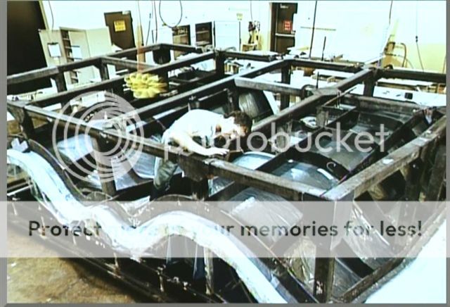
Just for completeness' sake, the photo posted by flanker shows YF-23 prototype manufacture.
This (rather old) article here claims the 117 engine thrust to be 9.5 tonnes. Sounds possible since that will give the 117 a wet/dry thrust ratio similar to 117S.
Regarding engine performance, I'm making a guess here, but maybbe the variable intake ramps can mitigate potential pressure recovery losses from RCS blocker?
Regarding engine performance, I'm making a guess here, but maybbe the variable intake ramps can mitigate potential pressure recovery losses from RCS blocker?
I don't mean to change the specific topic, but can anyone tell me the concensus on the length of the t-50? each time I see it quoted at 20.4 meters, I immediately find a quote for 19.4 meters. Sorry if this has been previously cleared up.
There are some talks and rumors of a stealthy compressor face due to some new kind of materials. Do these talks hold any water? A compressor face is pretty much directly facing the front, so I'm not quite sure how different materials or RAM will make that much difference.
- T-50-5 is almost ready for flight. MoD comision got a tour.
- Other source claimed T-50-6 will be the static frame (previous info said T-50-7) but it is reconfirmed: -7 is static. Current plan sets May as deadline.
- T-50-6 and -8 to follow.
This site uses cookies to help personalise content, tailor your experience and to keep you logged in if you register.
By continuing to use this site, you are consenting to our use of cookies.