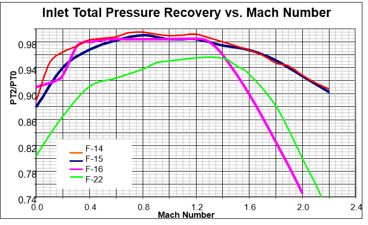
. The lack of adjusting the air intake throat in the F-22 aircraft is a disadvantage. For this reason, the air intake performance at supersonic flight regimes is below the level typical for adjustable air intakes (System Analysis of Technical Aspect of “Raptor” F/A-22 aircraft, Report of FGUP “GosNIIAS” No.68 (15396), 2005). Apparently, the air intake is not designed to fly with a Mach number over M=2.0
From what I have heard, the practical top speed of the F-22 is Mach 2.
On the other side, Su-57's air intakes are capable for Mach 3 .
СПОСОБ РЕГУЛИРОВАНИЯ СВЕРХЗВУКОВОГО ВОЗДУХОЗАБОРНИКА
Изобретение относится к авиационной технике, а именно к воздухозаборникам силовых установок сверхзвуковых самолетов. Преимущественной областью применения изобретения являются самолеты с ТРДД с максимальным числом Маха не более 3-х.
В качестве прототипа изобретения принят способ регулирования сверхзвукового воздухозаборника, при котором осуществляют изменение площади горла и положение скачков уплотнения (RU 2343297 C1). В известном решении реализуется пространственное торможение потока за счет использования V-образного клина (т.е. двух примыкающих друг к другу стреловидных клиньев, ориентированных друг к другу на виде спереди под тупым углом). Воздухозаборник выполнен с приданием стреловидности всем кромкам входа. Регулирование воздухозаборника осуществляется при помощи двух пар поворачивающихся относительно соответствующих осей панелей. Передние панели каждой из пар являются частью поверхностей торможения. Задние панели являются частью канала. При регулировании каждой пары панелей между их смежными торцевыми сторонами возникают поперечные щели, а между их боковыми сторонами возникают продольные щели как по стыкам с боковыми стенками, так и по стыкам друг с другом. Данное техническое решение имеет следующие недостатки:
- способ регулирования воздухозаборника не обеспечивает необходимую площадь горла на дозвуковых и малых сверхзвуковых скоростях полета, т.к. амплитуда перемещения подвижных панелей мала. В противном случаем возникают упомянутые продольные щели неприемлемых размеров. Это означает, что воздухозаборник не обеспечивает работу ТРДД во всем эксплуатационном диапазоне скоростей и не является многорежимным;
- технически сложная реализация способа регулирования воздухозаборника.
Технический результат, на достижение которого направлено изобретение, заключается в обеспечении возможности изменения угла раствора ступеней одного из стреловидных клиньев торможения и минимальной площади проходного сечения воздухозаборника (горла) без образования в его канале нежелательных продольных щелей и заедания подвижных элементов. Такое регулирование позволит, в свою очередь, обеспечить устойчивую работу двигателя на всех режимах полета летательного аппарата вплоть до числа Маха М=3.0 с коэффициентом восстановления полного давления на входе в двигатель на уровне не ниже типового для регулируемых плоских воздухозаборников и суммарной неоднородностью потока ниже максимально допустимой величины («Аэродинамика, устойчивость и управляемость сверхзвуковых самолетов», под ред. Г.С.Бюшгенса. - М.: Наука. Физматлит, 1998). При этом за счет параллелограммной формы входа воздухозаборника на виде спереди и придания всем его кромкам стреловидности достигается снижение РЛ-заметности объекта, на котором он установлен. Наибольший эффект снижения РЛ-заметности будет достигаться в случае, когда кромки воздухозаборника параллельны каким-либо элементам объекта (передним или задним кромкам крыла, оперения и др.).
METHOD OF ADJUSTING SUPERSONIC AIR INTAKE
The invention relates to aircraft technology, specifically to air intakes for supersonic aircraft power plants. The invention is primarily applicable to aircraft powered by turbofan engines with a maximum Mach number of no more than 3.
As a prototype of the invention, a method for regulating a supersonic air intake is adopted, in which the throat area and the position of the compression shocks are changed (RU 2343297 C1).In a known solution, spatial flow braking is achieved by using a V-shaped wedge (i.e. two adjacent arrow-shaped wedges oriented towards each other in the front view at an obtuse angle).
The air intake is designed with a sweepback shape at all inlet edges. The air intake is adjusted using two pairs of panels that rotate relative to their respective axes. The front panels of each pair are part of the braking surfaces.The rear panels are part of the channel. When adjusting each pair of panels, transverse gaps appear between their adjacent end faces, and longitudinal gaps appear between their side faces, both at the joints with the side walls and at the joints with each other.
This technical solution has the following disadvantages:
-The method of regulating the air intake does not provide the required throat area at subsonic and low supersonic flight speeds, since the amplitude of movement of the movable panels is small.
Otherwise, the aforementioned longitudinal gaps of unacceptable dimensions will appear. This means that the air intake does not support turbofan engine operation across the entire operating speed range and is not multi-mode;
- technically complex implementation of the air intake regulation method.
The technical result that the invention is aimed at achieving is to ensure the possibility of changing the opening angle of the steps of one of the arrow-shaped braking wedges and the minimum cross-sectional area of the air intake (throat) without the formation of unwanted longitudinal cracks in its channel and jamming of moving elements.
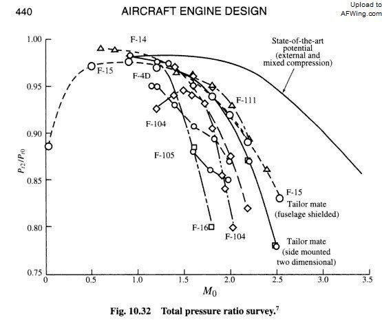
Such regulation will, in turn, ensure stable operation of the engine in all flight modes of the aircraft up to the Mach number M = 3.0 with a recovery coefficient of the total pressure at the engine inlet at a level not lower than the typical one for adjustable flat air intakes and a total non-uniformity of the flow below the maximum permissible value (“Aerodynamics, stability and controllability of supersonic aircraft”, edited by G.S. Byushgens. - M.: Nauka. Fizmatlit, 1998).
At the same time, due to the parallelogram shape of the air intake inlet in the front view and the fact that all of its edges are swept back, the radar signature of the object on which it is installed is reduced.
The greatest effect of reducing radar signature will be achieved when the edges of the air intake are parallel to some elements of the object (leading or trailing edges of the wing, empennage, etc.).

www1.fips.ru