Spruance-derived helicopter destroyer (DDH)

Triton

Donald McKelvy
Senior Member
Joined
14 August 2009
Messages
9,707
Reaction score
2,021
Website
deeptowild.blogspot.com
For fiscal year 1978, Congress authorized the production of two additional Spruance-class destroyers, though they funded only one. These were intended to be built as helicopter destroyers (DDH), provided they would not cost more than a standard Spruance-class. Litton-Ingalls completed design work for DDH-997, which moved the helicopter deck aft, stretching the length of the hangar and displacing the Sea Sparrow launcher to the top of the hangar. The design would have accommodated two SH-3 Sea Kings or four smaller SH-60 Seahawk or SH-2 Seasprite helicopters. While the prospective DDH-997 probably wouldn't have cost much more to build than a standard Spruance-class, the detail design and engineering work required before the ship could be built would have been substantial (similar work for the Kidd-class cost $110.8 million). This raised the cost of the DDH substantially above a standard Spruance-class destroyer. While this additional cost might have been justified if the DDH was going to enter series production, it was difficult to justify for a single ship. Accordingly the Navy built USS Hayler (DD-997) to the same design as the rest of the class.

http://en.wikipedia.org/wiki/USS_Hayler_%28DD-997%29
 

Attachments

  • DDH997.jpg
    DDH997.jpg
    30.3 KB · Views: 1,839
As depicted on Shipbucket:

USA%20DD-997%20Spruance_%20Hayler%201.gif
 
From Layman and McLaughlin's The Hybrid Warship: The Amalgamation of Big Guns and Aircraft:

The air defence and ASW potential of VTOL aircraft has led to the consideration of a new type of vessel, the 'air-capable' warship. There are links between the modern air-capable ship and the flying-deck cruiser of the 1930s, both in form and intended functions; another interesting reflection of the 1930s is the fact that the air-capable ship has come at one point to the attention of the US Congress.

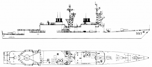
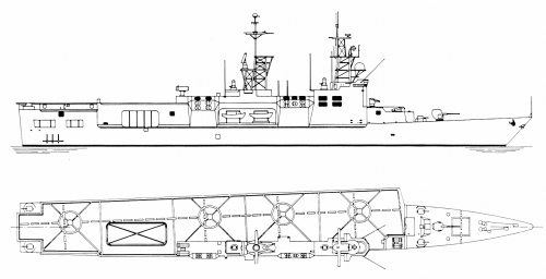
In the Fiscal Year 1978 shipbuilding programme, Congress approved the construction of a single air-capable Spruance (DD963) class destroyer. This would have involved simply increasing the size of the hangar and flight deck, allowing the ship to operate up to four helicopters, or, ultimately, some form of VTOL aircraft.

index.php


The US Navy did not really want this ship, and in the end managed to get the funds redirected to a standard unit of the class. However, the basic idea has inspired several other projects.

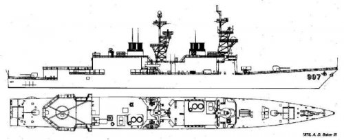
One of the earliest of these designs to appear was the work of Dean A Rains and Donald B Adams, both of Ingalls Shipbuilding Division, for a 'flight deck DD 963'. This proposal resembled Croker's 'through-deck cruiser', and called for a complete revision of the Spruance design. The beam would be increased from 55ft to 68ft, the superstructure would be rearranged and a hangar built on the main deck; there would be a flight deck forward of the hangar, including a ski-jump in some versions of the design, and a landing deck abaft it. In no meaningful sense a hybrid, this was really an attempt at a small carrier.
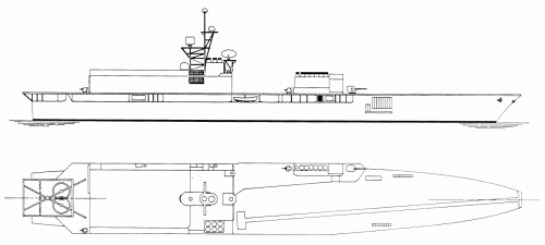
index.php


Another Spruance conversion design was worked out by the Grumman/Santa Fe Corporation and bears a strong resemblance to traditional hybrids. This scheme is one of several proposed 'mid-life' modernisations of the Spruance class ships. It shows the basic destroyer design from the bow to the after superstructure, but aft a large hangar has been built onto the hull, with a flight deck above. The resulting 9000 ton ship could embark as many as eight helicopters or four ASW VTOL aircraft; the sketches show an early version of the never-built Grumman turbofan Model 698 aircraft. This gull-winged aircraft featured swivelling engine nacelles attached to the fuselage and was intended to travel at up to 500 knots.

index.php


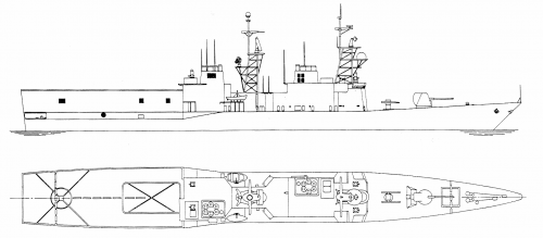
Still another Spruance-based VTOL design bore a strong resemblance to HMS Invincible and was intended to provide the advantages of STOL operations. Proposed by Commander Ronald J Ghiradella, US Naval Reserve, it featured a basic Spruance hull lengthened to 606ft overall; the gas turbine uptakes are trunked to starboard where an island superstructure is located, making room for a 470ft flight deck angling to port. Forward, there are conventional weapons: a 5in gun and Harpoon anti-ship missile canisters, with 30mm guns sited on each quarter to provide close-in AA defence, and a Basic Point Defense Missile System is located aft of the island. There is a long, narrow lift (62ft by 26ft) aft of the island. Ghiradella foresees two hangar decks, the main one on the original main deck, with a lower hangar deck extending from the lift aft to the stern. In spite of the fact that the lift is too narrow to handle Harriers, Ghiradella gives the aircraft complement as twelve 'medium-sized' helicopters and four 'Harrier-type' aircraft.

index.php


Source:
http://www.shipbucket.com/forums/viewtopic.php?f=17&t=2171
 

Attachments

  • GrummanSantaFeSpruance.png
    GrummanSantaFeSpruance.png
    169.3 KB · Views: 1,776
  • RainsAdamsSpruance.png
    RainsAdamsSpruance.png
    110.8 KB · Views: 1,726
  • SpruanceAirCapable.png
    SpruanceAirCapable.png
    176.5 KB · Views: 1,757
  • SpruanceInvincible.png
    SpruanceInvincible.png
    181.5 KB · Views: 1,819
Fascinating stuff. I never knew that these proposals existed.

I can see problems with all of these ideas. The "air capable destroyer" didn't really add much capability. Do an extra two helicopters really matter all that much? And it only makes sense if the plan was to put the ship into series production.

As for the more extensive redesigns, they too had a tough hill to climb. For starters, the Navy never wanted smaller carriers and the carrier mafia would have fought that like crazy. And if you want to support VTOL capability, the best way to do that was with the amphibious helicopter carriers and Harriers, just like the Navy did. Probably the only thing that could have made this concept viable would have been a VTOL anti-submarine aircraft. That would have allowed the small carriers to operate as sub hunters in the open ocean and might have made more sense.

There's a technical problem with the drawing for the "Invincible" version. Look at the side view. Note the level of the flight deck at the stern. Now note the level of the flight deck forward of the island. It's lower than the flight deck at the stern. Unless that flight deck angled downward, it wouldn't look like this. (Note also that on the side view there is what looks like a missile launcher forward of the island, but it's missing in the top view. Oops.) Also, note that the island is about the same width as the Sea Sparrow launcher, which is less than 12 feet wide. Can you really have an effective island only 12 feet wide?

Still, they're some neat ideas. Thank you for sharing.
 
Wouldn't these ships be useful as anti-submarine warfare (ASW) escorts for Atlantic convoys to Europe against Soviet submarines? Wasn't the idea to free aircraft carrier battle groups from convoy duty in the event of war in Europe? A variation of the Sea Control Ship (SCS) idea?
 
Triton said:
Wouldn't these ships be useful as anti-submarine warfare (ASW) escorts for Atlantic convoys to Europe against Soviet submarines? Wasn't the idea to free aircraft carrier battle groups from convoy duty in the event of war in Europe? A variation of the Sea Control Ship (SCS) idea?

Yeah, but the Spruance and the Perry's already performed that duty. That's why I think that the bigger variation would really only have made sense if they had a V/STOL anti-submarine aircraft with longer legs than a helicopter.
 
blackstar said:
Also, note that the island is about the same width as the Sea Sparrow launcher, which is less than 12 feet wide. Can you really have an effective island only 12 feet wide?

...and notice all the ducting for the gas turbine intakes and exhausts still have to go through them. It would be unworkable for that reason alone.
 
Great subject!
A pity I think that some of these designs were not pursued

Can I deviate a little and ask where I can find more on these Croker 'Through-Deck' design's ???

Regards
Pioneer
 
Looking at the other two designs, I cannot see how they would work either.

Look at the RainsAdamsSpruance design. Note that the forward exhaust is in front of the bridge. Now imagine the ship with a crosswind coming across the deck. Could that blow exhaust gasses straight at the bridge?

The GrummanSantaFeSpruance looks like it would also have problems. That's a lot of metal above the main deck, and a very high flight deck. It seems like it would roll a lot, and the flight deck, being so high, would move a lot in even moderate seas, making flight ops impossible.

Of all of these, the Air Capable Spruance looks like the only realistic design. If the Navy was going to build a bunch of them to increase the number of helicopters that each ship could bring to its duties, that might have made sense. But the Spruance was too small to get substantially more aircraft capabilities. You really needed a bigger ship, such as the proposed Sea Control Ship from earlier in the decade.
 
If the USN decided it had wanted to operate more Sea Kings in support of the smaller LAMPS helos, constructing a few bigger-hangar destroyers after the JMSDF DDH types might have been reasonable, though obviously a luxury.
 
Madurai said:
If the USN decided it had wanted to operate more Sea Kings in support of the smaller LAMPS helos, constructing a few bigger-hangar destroyers after the JMSDF DDH types might have been reasonable, though obviously a luxury.

It would be worthwhile comparing the capabilities of the Sea Kings and the LAMPS at that time. The Sea King was generally headed for retirement, and I suspect that they were not being upgraded as much as the LAMPS was.
 
In 1978? That's another 15 years before they were fully replaced by the SH-60F.
 
Madurai said:
In 1978? That's another 15 years before they were fully replaced by the SH-60F.

But they were not carrying the full electronics capabilities of the LAMPS. Could a Sea King do what a LAMPS was doing at the time?
 
Given that LAMPS III didn't reach the fleet until 1985, Sea King was clearly the superior option compared to LAMPS I.
SH-3H had the same basic sonobouy setup as LAMPS I, plus a dipping sonar. By the mid-1980s, Sea King also had on-board rather than off-board sonobouy processing. Frankly, it was superior in many ways. It's just that the USN felt (for some reason) that it was too big for small ships.
 
Okay.

The Navy did use the Sea King a lot for search and rescue during Vietnam, operating it from destroyers and frigates, although apparently not basing it on them. This might have convinced Navy brass that it was too big to operate from anything other than carriers.
 
I've found this artist painting depiction of the then ordered Spruance class destroyers from 1970. Intriguing is the mirrored funnels eg the forward funnel is on the starboard side and the aft on the port instead of the other way around as on the real ships and on the Ticonderogas as well as they are more streamlined.
Simpler mast structures not that forward leaning as on the final ships, and what looks like to be some sort of variable depth sonar launching apparatus on the stern?
View: https://i.imgur.com/j1CzrbU.jpg

j1CzrbU.jpg
 
The attached comes from a (very bad) scan of Conway’s All The World’s Fighting Ships 1947-1995…
It was actually a second edition covering this period, the original was split into two volumes NATO and Warsaw Pact Navies…
 

Attachments

  • F3E6DEB2-7468-45AB-9D2D-4B223916F098.jpeg
    F3E6DEB2-7468-45AB-9D2D-4B223916F098.jpeg
    119.9 KB · Views: 241
I've found this artist painting depiction of the then ordered Spruance class destroyers from 1970. Intriguing is the mirrored funnels eg the forward funnel is on the starboard side and the aft on the port instead of the other way around as on the real ships and on the Ticonderogas as well as they are more streamlined.
Simpler mast structures not that forward leaning as on the final ships, and what looks like to be some sort of variable depth sonar launching apparatus on the stern?
View: https://i.imgur.com/j1CzrbU.jpg

j1CzrbU.jpg

The original Spruance spec called for the SQS-35 Independent Variable Depth Sonar (IVDS), also fielded in some Knox class DEs. The passive towed array (TACTASS) that became the ultimate fit was as yet unproven but became the preferred solution while the ships were in development. (But not quite soon enough -- a few ships had van-mounted TACTASS before the proper version was available.)

The transom cutouts were apparently for long-range chaff rockets, probably the second-generation Mk 84 CHAFROC. This was an early effort at antiship missile defense and was really tricky to use, since it had to be illuminated by a shipboard repeater jammer (ULQ-6) to actually accomplish a pull-off deception. It was rapidly replaced by RBOC/Super RBOC, which generated clouds with much larger RCS.

I'm not clear on why the stacks (and thus machinery spaces) in this drawing are reversed from the actual ship. They did got through a ton of machinery configurations (steam, 3 or 4 gas turbines, multiple CODAG and COSAG options, etc.). The offset stacks were considered a novelty but freed up space for the hangar. I think the choice of which machinery room would be to port and which to starboard was more or less arbitrary, so possibly it changed over time. Or possibly this was just an artist's error.

The streamlined stacks in the early drawings apparently stemmed from a conscious choice by the Litton design team to emulate the RN County class aesthetics. Some very basic tests (asking a bunch of aircraft execs) suggested that the County shape made ships look larger and more impressive than the comparable USN ships, the Farragut class.

(Source for this is mostly Electronic Greyhounds by Capt. Michael C. Potter, USNR).
 
Last edited:
I see, thanks! Is there more info on the various Spruance preliminaries?
Also wouldn't these ships considered for AEGIS conversion knowing that the Ticonderogas are basically Spruances with different superstructures?
 
I see, thanks! Is there more info on the various Spruance preliminaries?
Also wouldn't these ships considered for AEGIS conversion knowing that the Ticonderogas are basically Spruances with different superstructures?

Oh, they're way more modified than that. The Ticos were really marginal in stability thanks to the extra weight to the AEGIS deckhouses. So they have a bunch of specialized design changes to give them acceptable stability margins -- thicker hull plating, strengthened bulkheads, a cross-flooding duct, fuel tanks replacing voids, and a bunch of ballast. You could not take an existing Spruance hull and add AEGIS while preserving the acceptable stability limits.

Electronic Greyhounds has a really good discussion of the original Naval Ship Engineering Center DX and DXG notional designs, the various permutations of the Litton design, some notes on the competing alternatives from Bath Iron Works/Gibbs & Cox and General Dynamics, and even NavSEC's unsolicited alternative.
 
I see, thanks! Is there more info on the various Spruance preliminaries?
Also wouldn't these ships considered for AEGIS conversion knowing that the Ticonderogas are basically Spruances with different superstructures?
There were a few designs under DX AEGIS but all of them had the issue of not having enough weapon.

They basically either had a single Mk26 with 44 shots or two Mk13s and no guns. This was due to both cost and weight limits of the hull.

The Ticos while were a Spraunce base hull did get seversl modes to their hull to allow the fitting of the Twin Mk26s, later MK41s, the two 5 inchers, and Aegis.

Shipbucket has a good break down of several of the designs.

 
Is there a source, book or site providing the data of these designs? Dimensions engines, armament etc?
 
Is there a source, book or site providing the data of these designs? Dimensions engines, armament etc?

Most of that Shipbucket thread is from US Destroyers by Friedman, I think (some only in the text, with the drawings being speculative). The air-capable designs are probably from The Hybrid Warship by Layman and McLaughlin. And the competing designs I mentioned are from Electronic Greyhounds by Potter.
 
Last edited:
Thank you for the compliment @Firefinder, I worked long and hard on Project DX, and I hope to find the time to expand it further, update the drawings and text a bit and fix some small errors I have learned off later.

TomS, I have the general dynamics iterations work in progress but got stuck at some point. The curse of the perfectionist: do it well or don't do it. I do hope to add them in the future though.....

Tzoli, the sources for these designs and the accompanying text is indeed Electronic Greyhounds, US Destroyers and various articles I gathered over the years (maybe even threads here on secretprojects). If "The Hybrid Warship" expands on the information I have gathered for that, I might want to add it to my bookshelf.

Something which might be off note of the original spruance spec, is that at that point the ship had only 3 LM2500 gas turbines but had an electrical cross connection between the shafts. The mirrored arrangement of the propulsion layout might have been related to the changes in the propulsion when that was changed to 4 LM2500 as the navy would rather have more power and less efficiency (trailing one shaft when running on one turbine) then the electrical cross connection between the shafts. I would have to check my books to see if this swap of engine rooms and shafts was related to that, I do recall that the swap was mentioned in the text (so it is not an drawing error by the artist of this artist impression)

The offset funnels and air intakes were a direct result of the COGAG arrangement with 1 or 2 turbines per shaft; the more length uptakes and intakes are for gas turbines, the larger their diameter has to be. As there was no real need to keep the intakes and uptakes amidships (and even some advantages to not being amidships by having these spaces next to the hangar allowing for a single big hangar instead of a split one), the turbines could be lifted for off-ship maintenance directly up trough the air intake channels, and the channels could all go straight up from the turbines, which were of course not positioned amidships but off-centre too, with their respective shafts.
 
TomS, I have the general dynamics iterations work in progress but got stuck at some point. The curse of the perfectionist: do it well or don't do it. I do hope to add them in the future though.....

No worries. I'd be a little cautious with the Electronic Greyhounds drawing as a source. It's by the author, not official, and I suspect he cribbed part of it from a DDG-51. The flight deck and hangar geometry looks like G&C, not General Dynamics.

I would have to check my books to see if this swap of engine rooms and shafts was related to that, I do recall that the swap was mentioned in the text (so it is not an drawing error by the artist of this artist impression)

You're right. Or at least, the switch happened during the design refinement process along with the elimination of the electric cross-connect. Electronic Greyhounds says it improved helo ops when operating with a carrier. With the destroyer steaming parallel to the carrier during flight ops (with the wind down the angle on the carrier), the same wind would carry exhaust from the aft (starboard) stack clear of the helo deck instead of across it. Talk about a subtle change!
 
Reuven Leopold's Innovation Adoption in Naval Ship Design includes a list of description of all the types of propulsion investigated by Litton for their DX design which became the Spruance.

The writing is tiny and the scans are not of the best quality, so it is difficult to fully parse the information:

Screenshot_20210224-212244~2.png
Screenshot_20210224-212253~2.png
Screenshot_20210224-212306~2.png
Screenshot_20210224-212316~2.png
 
Found this drawing (for sale apparently) showing the same layout as the one I've posted earlier but with more details in cut-away sections:
 
Found another Spruance variant model photo from a German book or magazine, showing the Spruance with more squere-ish superstructure elements and separate forward and aft superstructures.
View attachment 694644
That's Bath Iron Works competitor to Litton's winning design. Overall length was 571 ft 6 in, Length Between Perpendiculars was 530 ft, Beam was 61 ft 6 in. Powerplant was four LM2500s of FT-4s with mechanical cross-connect. The forward pair of turbines drove the port shaft, and the aft pair the starboard shaft, but the arrangement of the gearing and parallel shafts ensured that any single turbine could drive both shaft at low power. There were two side-by-side forward stacks, acting as ballistic protection for the CIC which was nestled between them. There were modernisation margins for 300 tons high up in the ship.
 
Last edited:
Found another Spruance variant model photo from a German book or magazine, showing the Spruance with more squere-ish superstructure elements and separate forward and aft superstructures.
View attachment 694644

Excellent find. If I'm not mistaken, that's the Gibbs& Cox/Bath Iron Works alternative design.

This ship was shorter than the Litton proposal. Note the BPDMS on the hangar roof instead of aft of the flight deck, and the Sea King helicopter on the flight deck.
 
Found another Spruance variant model photo from a German book or magazine, showing the Spruance with more squere-ish superstructure elements and separate forward and aft superstructures.
View attachment 694644
That's Bath Iron Works competitor to Litton's winning design. Overall length was 571 ft 6 in, Length Between Perpendiculars was 530 ft, Beam was 61 ft 6 in. Powerplant was four LM2500s of FT-4s with mechanical cross-connect. The forward pair of turbines drove the port shaft, and the aft pair the starboard shaft, but the arrangement of the hearing and parallel shafts ensured that any single turbine could drive to drove both shaft at low power. There were two side-by-side forward stacks, acting as ballistic protection for the CIC which was nestled between them. There were modernisation margins for 300 tons high up in the ship.
So it has basically 3 funnels?

Yes. (or four, with the two aft ones trunked together, which is kind of a semantic difference).

It's interesting that this design was rated as highly competitive with the Litton design. I see a lot of issues that would come back to bite them on the possible conversion to a DDG and especially to AEGIS. Most obviously, where does the aft Mk 26 or VLS go? I think you have to lose either the aft 5-inch gun or the helo hangar.

Potter says the wider beam would make the AEGIS conversion easier, which is true, to a point. But the rest of the arrangement is so constrained that you'd probably struggle to match the missile capacity of the Ticos as built.
 
TomS, I have the general dynamics iterations work in progress but got stuck at some point. The curse of the perfectionist: do it well or don't do it. I do hope to add them in the future though.....

No worries. I'd be a little cautious with the Electronic Greyhounds drawing as a source. It's by the author, not official, and I suspect he cribbed part of it from a DDG-51. The flight deck and hangar geometry looks like G&C, not General Dynamics.
Is there an possibility of another source existing for this? I mean cross-referencing with something could solve me being stuck on her as well ;)
 
And from Friedman's book the Fire Support Ship variants of the Spruance:
View attachment 696340
Is anything mentioned in the book about the propulsion arrangement? I find it interesting that she would still have 2 big funnels for only a quarter of the propulsive power. It seems like a lot of ship (and cost) for what it would be (which makes us understand why she was never build)
 
Is anything mentioned in the book about the propulsion arrangement? I find it interesting that she would still have 2 big funnels for only a quarter of the propulsive power. It seems like a lot of ship (and cost) for what it would be (which makes us understand why she was never build)
No nothing. likely the Gas Turbines were to be re-rated / reduced to 10.000shp per module (If I'm right there was 4 20.000shp units installed, 2 per shaft 1-1 for high speed dash and 1-1 for economical cruising)
 
Regarding the 3 Spruance derivatives that were built: Spruance, Kidd and the Ticonderoga classes.
Which was the most capable?
Also didn't the Kidds were considered for VLS modernization?
 

Similar threads

Back
Top Bottom