Shenyang / Chengdu "6th Gen" Aircraft - General Discussion and Speculation

Yes, the GCAP features substantially improved power generation capability compared to previous generation fighter aircraft. Nevertheless, my personal assessment is that a peak generating capacity of 1 MW is still too conservative for the J‑36, considering that according to leaks, the J‑36 places heavy emphasis on electronic warfare. Both its large airframe and two‑seat configuration are tied to its EW requirements.

The WS-15 is expected to produce more power than the WS-10... having three engines means 50% more power... and not all systems will scale in their power draw the way radar or jammers will. So, even without improvements in the ability to draw extra power from the engine - we're still talking about an 150% more power than a late model J-20 and 200% more power than an early model J-20. So it could still be a major increase in capacity even without taking any additional steps to draw more power from the engines.

Given the implied power to weight ratio and relatively limited thrust requirements in cruise they could probably add additional mechanisms to draw power from the engines... which would increase those numbers further - but I don't think it is necessarily implied that they will need to in order 'place heavy emphasis on electronic warfare'. That said, if they did plan a modified engine to allow increased electricity production... ...I wonder if the reason for the dorsal engine placement is partly to fit a larger heat exchanger for cooling electronics?
 
Doesn’t the beam attenuate towards the edges of the radar? I’d imagine there will be some tradeoff form looking at head on targets.
I dont really see that as a concern. If you think of the total system then instead of each ship staring forward, each ship simply covers adjacent ships' sectors (total fused picture makes this a lot less confusing than in the past). When you bring in other offboard sensors into the picture like CCAs, AWACS, and legacy platforms, this becomes even less of an issue. Instead, it seems advantageous to me that the ownship arrays would be tailored for immediate tactical needs, and sidelooking arrays seem smart in that regard.
 
Doesn’t the beam attenuate towards the edges of the radar? I’d imagine there will be some tradeoff form looking at head on targets.
I'm not sure, not enough of a radar nerd to understand that.

It's my understanding that the overlap between the two arrays at ~45-50deg ~90-100deg eliminates that issue.

Edit: used sweep angle, not full included angle between arrays.
 
Last edited:
Not sure I like starter-generators inside the spools, that's going to greatly suck for maintenance.

The classic "starter-generator in the inlet bolted onto the front of the compressor" like J34 and J79 may be a better option (not sure how well or even if that works with a multi-spool engine). @F119Doctor can you start a multi-spool engine by starting the LP compressor?
A two spool turbojet, maybe. A two spool turbofan is unlikely since a lot of low spool airflow bypasses the core and doesn’t assist the turning of the core. The F100-100/200/220 (0.7 BPR) requires approximately 350 KIAS speed to perform a windmill air start. I doubt a low spoil starter motor could match that level of airflow to the core rotor.

That said, there is a lot of discussion with starter / generators mounted on both the low and high spools, primarily to provide additional electrical power for aircraft systems without overly loading the high spool. Could a low spool starter help the high spool starter? Would take a ton of current to operate both.
 
A two spool turbojet, maybe. A two spool turbofan is unlikely since a lot of low spool airflow bypasses the core and doesn’t assist the turning of the core. The F100-100/200/220 (0.7 BPR) requires approximately 350 KIAS speed to perform a windmill air start. I doubt a low spoil starter motor could match that level of airflow to the core rotor.
I was afraid of that.


That said, there is a lot of discussion with starter / generators mounted on both the low and high spools, primarily to provide additional electrical power for aircraft systems without overly loading the high spool. Could a low spool starter help the high spool starter? Would take a ton of current to operate both.
Still means two starter-generators in very hot places that are an absolute nightmare to repair or replace.
 
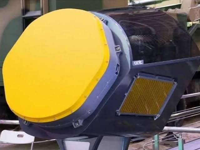
What you think about the seemingly extreme nose radome canting? Is some kind of V-shaped array possible?
Well, first it gets the radar away from glinting directly forward.

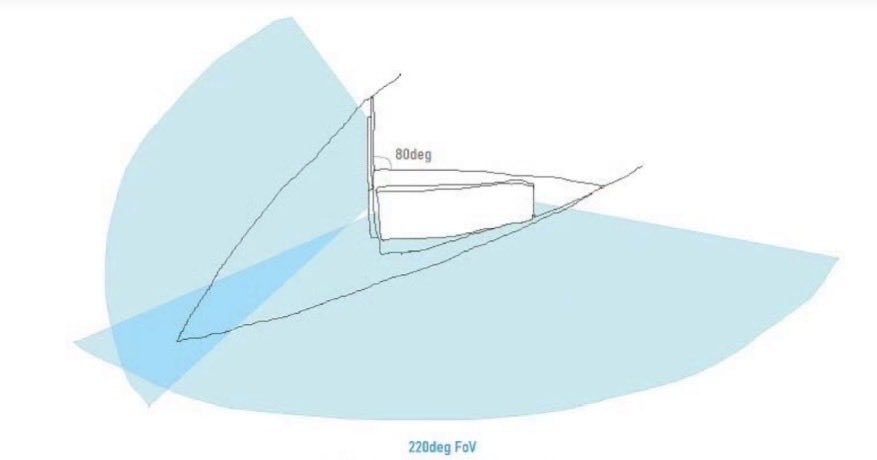
ESAs of both types have been demonstrated with 90deg between arrays (45deg "sweep") and seamless tracking as an object moves around them. One of the SPY6 versions (v3?) can handle 120deg between arrays (60deg "sweep") but apparently has some loss of data fidelity at the edges, 90deg is much preferred there.

But it'd be possible to have two arrays in there matching the ~50deg sweep of the main leading edges with no trouble. So now your nose radar is covering +-100deg across the front of the plane. Able to track a target abeam(!).
Doesn’t the beam attenuate towards the edges of the radar? I’d imagine there will be some tradeoff form looking at head on targets.
Might I also suggest – an isosceles trapezoidal arrangement (when viewed from above)? So one front-facing array flanked by two side-facing arrays (of comparable size) integrated into a single unit. Gives you even more area for the T/R modules and I imagine the implication of overlapping FoVs from a singlular radar unit is quite nice.

So basically this but significantly better.
 

Attachments

  • 1789744697507.jpeg
    1789744697507.jpeg
    25 KB · Views: 155
Last edited:
A large, highly advanced and complex tri-engine jet will be maintenance hog anyway I'd assume
Right, but when the generator bolted onto an accessory drive fails you can unbolt it from the accessory drive housing and replace it, engine still in the plane.

While when a generator inside the spools fails you have to pull and then disassemble the engine.

That's an order of magnitude difference in how long to repair. At least.
 
Might I also suggest – an isosceles trapezoidal arrangement (when viewed from above)? So one front-facing array flanked by two side-facing arrays (of comparable size) integrated into a single unit. Gives you even more area for the T/R modules and I imagine the implication of overlapping FoVs from a singlular radar unit is quite nice.
I'd need to crunch specific numbers, but I think you'd get more array area with just two large "side" arrays and skipping the forward array entirely. Plus not having a forward array means you have one less RCS spike direction.

Does anyone know how deep a typical GaN TRM is, how far the TRM goes into the backing plate? 10cm? 5?
 
I'd need to crunch specific numbers, but I think you'd get more array area with just two large "side" arrays and skipping the forward array entirely. Plus not having a forward array means you have one less RCS spike direction.

Does anyone know how deep a typical GaN TRM is, how far the TRM goes into the backing plate? 10cm? 5?
I was gonna do a numerical estimate but after thinking about it, it's highly context-dependant. The exact radome shape changes a lot of things, so it's probably better off to model the different configurations in CAD then estimate it.

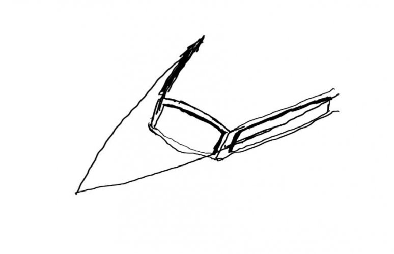
A v-shaped array might look like this:
HSi1Mr0bgAAwIzD.jpg

And a trapezoidal one might look like this (excuse the incredibly crappy quick sketch):
HSi1MZ-aoAA1tr9.jpg

Theoretically the latter gives you even more area via a more aggressive utilisation of the radome space + slight slanting. A v-shaped array might also do this BUT since the volume shrinks as you approach the front, it's probably more awkward.

Gives you more FoV, overlap, and more importantly, bistatic operation over a much wider range for LPD/LPI. A wedge array can only do that to a significantly more limited fashion frontally.
 
Last edited:
Geometry aside Transceiver size has the final practical say. And having 3 separate ones is the better practical solution for density, aperture size & resolution, and range to the detriment of mass & power, though.
 
I was gonna do a numerical estimate but after thinking about it, it's highly context-dependant. The exact radome shape changes a lot of things, so it's probably better off to model the different configurations in CAD then estimate it.

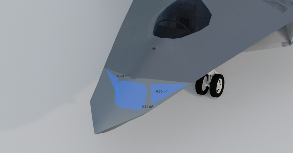
Two configurations.
 

Attachments

  • 1789792797138.png
    1789792797138.png
    835.1 KB · Views: 117
  • 1789792847934.png
    1789792847934.png
    1.2 MB · Views: 133
Two configurations.
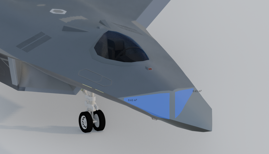
Fantastic work. The difference is 0.08 m^2 in this case. I'll admit the wedge array is significantly easier to optimise for but I'm sure the tri-array arrangement can have the same (if not more?) area with a little more aggressive use of the available radome volume though, since the whole point was pushing the front array a bit forward so that the side arrays wouldn't be smaller than the wedge solution + FoV gains.
 
Last edited:
To my very uniformed eyes, the tri-array has the apparent disadvantage of the side-arrays not seeing directly in front, with the frontal array being smaller than the radome size would allow, impacting range/EW etc. The V-shaped array however allows both arrays to see in front with the maximum number of TRMs. Of course there is some loss in lateral FOV compared to the triple solution, but still offers a much wider FOV than a conventional fixed array. It seems to be the best compromise, but i guess we'll have to wait years or decades to actually find out the solution they chose.
 
To my very uniformed eyes, the tri-array has the apparent disadvantage of the side-arrays not seeing directly in front, with the frontal array being smaller than the radome size would allow, impacting range/EW etc. The V-shaped array however allows both arrays to see in front with the maximum number of TRMs. Of course there is some loss in lateral FOV compared to the triple solution, but still offers a much wider FOV than a conventional fixed array. It seems to be the best compromise, but i guess we'll have to wait years or decades to actually find out the solution they chose.
But AESAs don't need to be physically pointed towards a target. The beam is electronically steered, which is the whole point. The side arrays for the tri-array solution can of course see forward, but they don't necessarily need to (for the most part). There's the front array for that, while the side arrays can look for off-bore targets for better situational awareness.

And the thing with the v-array is that when it looks directly forward, both panels are scanning heavily off-broadside, which means (potentially significant) cosine loss. Realistically the effective aperture area is much smaller. Even if it can house more TRMs (it might not) there could be no tangible advantage since they aren't radiating efficiently in that direction.

There's also kinda an elephant in the room. The v-shaped array forms a big ahh cavity so you get a dihedral corner reflector.
 
There's also kinda an elephant in the room. The v-shaped array forms a big ahh cavity so you get a dihedral corner reflector.
That's why it's not a 90deg corner, but closer to an 80deg corner.

Edit: I was also assuming that the arrays would be angled down slightly, maybe 10-15deg or whatever the lower-side angle of the fuselage is.
 
Last edited:
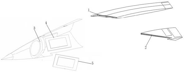
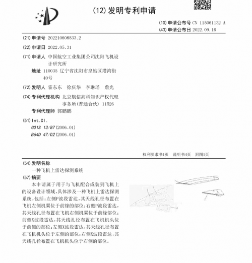
A radar patent filed around the same time as the J-XDS nose design patent by SAC, and figure shows a very slender nose and a three-sided radar array.
A Radar Detection System on an Aircraft
China National Intellectual Property Administration
Invention Patent Application
Application Publication No. CN115061132A (43) Date of Publication 2022.09.16
Application No. 202210608533.2
Date of Filing 2022.05.31
Applicant: Shenyang Aircraft Design and Research Institute of Aviation Industry Corporation of China (AVIC)
Address: No. 40 Tawan Street, Huanggu District, Shenyang, Liaoning 110035, China
Inventors: Huo Dongdong, Xu Qinghua, Li Linyao, Zhan Guang
Patent Agency: Beijing Hangxin Gaoke Intellectual Property Agency (General Partnership) 11526
Patent Attorney: Guo Pengpeng
Int. Cl.: G01S13/87 (2006.01); B64D47/02 (2006.01)

Abstract:
The present application belongs to the field of design of equipment for use with or mounted on aircraft, and specifically relates to a radar detection system on an aircraft, comprising: a left P-band radar, whose antenna aperture is arranged at a leading-edge portion of the left wing of the aircraft; a right P-band radar, whose antenna aperture is arranged at a leading-edge portion of the right wing of the aircraft; a front X-band radar, whose antenna aperture is arranged at a front portion of the nose of the aircraft; a left X-band radar, whose antenna aperture is arranged at a left portion of the nose of the aircraft; and a right X-band radar, whose antenna aperture is arranged at a right portion of the nose of the aircraft.

Claims:
  1. A radar detection system on an aircraft, characterized in that it comprises:
    a left P-band radar (1), whose antenna aperture is arranged at a leading-edge portion of the left wing of the aircraft;
    a right P-band radar (2), whose antenna aperture is arranged at a leading-edge portion of the right wing of the aircraft;
    a front X-band radar (3), whose antenna aperture is arranged at a front portion of the nose of the aircraft;
    a left X-band radar (4), whose antenna aperture is arranged at a left portion of the nose of the aircraft;
    a right X-band radar (5), whose antenna aperture is arranged at a right portion of the nose of the aircraft.
  2. The radar detection system on an aircraft according to claim 1, wherein the antenna apertures of the front X-band radar (3), the left X-band radar (4), and the right X-band radar (5) are distributed on the top side and two lateral sides of a trapezoid.
  3. The radar detection system on an aircraft according to claim 1, wherein among the left P-band radar (1), the right P-band radar (2), the front X-band radar (3), the left X-band radar (4), and the right X-band radar (5), signal processing modules are configured separately according to the P band and the X band.
  4. The radar detection system on an aircraft according to claim 1, wherein the left P-band radar (1), the right P-band radar (2), the front X-band radar (3), the left X-band radar (4), and the right X-band radar (5) share one broadband signal processing module.
  5. The radar detection system on an aircraft according to claim 3 or 4, wherein the left P-band radar (1), the right P-band radar (2), the front X-band radar (3), the left X-band radar (4), and the right X-band radar (5) share one digital signal processing module.
......

[0020] For the radar detection system on an aircraft disclosed in the above embodiment, a person skilled in the art can understand that the radar detection system on an aircraft is designed to comprise a left P-band radar 1, a right P-band radar 2, a front X-band radar 3, a left X-band radar 4, and a right X-band radar 5, i.e., P-band radar and X-band radar are simultaneously integrated on an aircraft. When the aircraft executes a mission, the P-band radar thereon can perform long-range position detection of a mission target, and after approaching the mission target, the X-band radar thereon performs short-range high-precision detection of the mission target. There is no need for formation cooperation with other aircraft, which can reduce the number and types of aircraft required to perform the mission, facilitate support and maintenance, and does not require complex cooperation strategies between aircraft, is easy to operate, has no problem of flight performance matching, has relatively high mission execution efficiency, and communication is limited to the interior of the aircraft, reducing the possibility of communication being interfered with.
[0021] For the radar detection system on an aircraft disclosed in the above embodiment, a person skilled in the art can also understand that the space required for arranging the antenna aperture of a P-band radar is relatively large, and generally only the leading-edge portion of the left wing and the leading-edge portion of the right wing on an aircraft have sufficient space for arrangement. The P-band radar is designed to comprise a left P-band radar 1 whose antenna aperture is arranged at the leading-edge portion of the left wing and a right P-band radar 2 whose antenna aperture is arranged at the leading-edge portion of the right wing, fully considering the space on the aircraft and enabling a relatively large angular difference therebetween, so that long-range detection in a relatively large angular range can be achieved.
[0022] For the radar detection system on an aircraft disclosed in the above embodiment, a person skilled in the art can also understand that arranging the antenna apertures of the front X-band radar 3, the left X-band radar 4, and the right X-band radar 5 at the nose of the aircraft can reduce the possibility and intensity of electromagnetic interference, and helps ensure the accuracy of short-range detection.

 

Attachments

  • 1789967657121.png
    1789967657121.png
    53.5 KB · Views: 235
  • 1789967700364.png
    1789967700364.png
    181.7 KB · Views: 239
Last edited by a moderator:
P is 280- 440 MHz, 1m wavelength +-. J-XDS increasingly appears as a "super felon" of sorts. Maybe befitting Shenyang product and a likely J-11/16 replacement.

Though I wonder how they're going to get low-band arrays in leading edges somehow stealthy... and at this antenna size, will it be just 1 row? Much higher array base(between pairs of arrays) than Felon, too, though this also is likely at least partially about band.

Band is curious in many ways; it's less universal than L, but it could also potentially jam the E-2 AEW series in your line fighter, with all sorts of interesting implications.
(and btw it is not unlikely that J-36 will have the same array in the leading edge).

Lots of questions, but tactical implications, putting it mildly, are very significant.
 
Last edited:
I’m not sure the two are completely comparable since the proportion of new tech on J-36 is much higher. That said, there is reliable news that they can LRIP before 2030.

I'm not so sure about there being a greater proportion of new tech on the J-36 to be honest... the technological jump from the J-10 to the J-20 might be higher than between the J-20 and the J-36. This is especially true if the first production variant uses a similar (but slightly enlarged) radar and the WS-15... aside from the flight control system - is there anything that we know for sure is a truly new type of technology that isn't seen on the J-20? Perhaps the EO/IR tracking system?
 
Last edited:
That and probably cheek arrays and some more.
 
Last edited by a moderator:
I'm not so sure about there being a greater proportion of new tech on the J-36 to be honest... the technological jump from the J-10 to the J-20 might be higher than between the J-20 and the J-36. This is especially true if the first production variant uses a similar (but slightly enlarged) radar and the WS-15... aside from the flight control system - is there anything that we know for sure is a truly new type of technology that isn't seen on the J-20? Perhaps the EO/IR tracking system?
Well from the looks of things when talking about programs from other countries, the ‘jump’ is more internal, the sensor fusion cloud, networking, AI, computational, radar processing, systems, electronics and a more digital and power centered architecture, aka. All the tech buzzwords. All these are basically non-visible, but could genuinely provide just as large of a leap in design and combat power than physical features.

This basically means we are essentially privy to none of that, as at least in 5th gen and below, many of the technological innovations were visible on the exterior, and access to top secret info wasn’t necessarily needed to gauge a fighters performance, but now we are screwed.

I mean just thinking about J-36 potentially running 3x VCE with a focus on power and cooling and what that can enable on the platform. It would be a generational leap compared to J-20. With progress on Chinese VCE rumored to be progressing well, I could see only the first batches would equip modified WS-15 engines as an interim solution. “WS-15G” as it is known, may be a stopgap with improved power and cooling specifically for the J-36.
 
Last edited:

Similar threads

Back
Top Bottom