It appears that SR were simply putting the case for flying boat development post war, their ideas being refered to as schemes or suggestions and not progressing beyond the study stage (according to the Putnam volume). This no doubt explains the artwork bearing such a strong resemblance to the A.37 Shrimp, a logical basis. The shift in favour towards land-based long range civil transports was contentious at the time, so Gouge and Fowler were keen to demonstrate the capabilities of flying boats.
 
http://www.fzt.haw-hamburg.de/pers/Scholz/dglr/hh/text_2010_06_03_SR_Princess.pdf


This link was already posted above with no comments - its a 215 page presentation "Saunders-Roe and the Princess Flying Boat" by Bob Wealthy for the Hamburg Branch of the Royal Aeronautical Society. It has some great stuff in it, including a landplane Princess, Nuclear Princess, Twin Princess, Duchess jet powered flying boat, twin-deck Duchess derivative and P.192 as well as lots of photos and drawings of the Princess.
 
PaulMM (Overscan) said:
This link was already posted above with no comments...

By all means, please let me be the first one to say this is an excellent, comprehensive and fascinating document. My only caveat concerns the Nuclear Princess, which was primarily (if not exclusively) a cooperative project with Convair San Diego, not Glenn Martin. There is ample supporting documentation at the Convair archive (SDAM).

Other than that, it's a must-read PDF.
 
PaulMM (Overscan) said:
http://www.fzt.haw-hamburg.de/pers/Scholz/dglr/hh/text_2010_06_03_SR_Princess.pdf


This link was already posted above with no comments - its a 215 page presentation "Saunders-Roe and the Princess Flying Boat" by Bob Wealthy for the Hamburg Branch of the Royal Aeronautical Society. It has some great stuff in it, including a landplane Princess, Nuclear Princess, Twin Princess, Duchess jet powered flying boat, twin-deck Duchess derivative and P.192 as well as lots of photos and drawings of the Princess.


Anther amazing PDF my dear Paul,


and a nuclear powered version of Princess,from the same source.
 

Attachments

  • Nuclear-powered Princess 1.JPG
    Nuclear-powered Princess 1.JPG
    46.9 KB · Views: 2,047
  • Nuclear-powered Princess 2.JPG
    Nuclear-powered Princess 2.JPG
    30.9 KB · Views: 2,045
PaulMM (Overscan) said:
This link was already posted above with no comments

Ouch. Typically the kind of file I save onto my computer for later viewing and then forget about. It is in my Princess file all right... :(
Thanks a lot for the reminder Paul!
 

Attachments

  • Saro Queen pic1.jpg
    Saro Queen pic1.jpg
    51.4 KB · Views: 604
  • scan0015.jpg
    scan0015.jpg
    20.5 KB · Views: 607
  • b27263df.jpg
    b27263df.jpg
    44.5 KB · Views: 603
  • duchess.jpg
    duchess.jpg
    25.4 KB · Views: 244
  • saro queen pic2.jpg
    saro queen pic2.jpg
    13.8 KB · Views: 204
  • Saro Queen 3 side view.jpg
    Saro Queen 3 side view.jpg
    33.8 KB · Views: 255
Someone posted a presentation as pdf file about history of the Saunders Roe and the Duchess. I seem to recall that the Queen was also mentioned there.
 
Never seen it called the 'Saro Queen' before, it's always been the P.192...

cheers,
Robin.
 
In 1958, the U.S. Navy sponsored a study of the application of nuclear propulsion to the
Saunders-Roe "Princess" flying boat. The companies participating in the study were
Saunders-Roe, the Martin Company, and Convair - San Diego for the aircraft, and General
Electric and Pratt and Whitney for the nuclear power plants.


Confirmation both Convair and Martin worked on nuclear Princess designs. Some drawings in the PDF linked below.


Source:

APEX-910: Aircraft Nuclear Propulsion Application Studies
http://www.osti.gov/scitech/servlets/purl/1048126
 
Such an amazing PDF file... I don't know how you landed on that page but that was inspired!!!
 
So what are we seeing here?

The bombs and (20mm?) cannon make sense. I'm unclear about what the forward fold-out bay contains or what the big sensor is though.
 
Good question about that forward bay, perhaps rocket launchers, as unguided rockets still were
an important weapon against subs ?
The Saro P.104 actually is an interesting project, according to Chris Ashworth "RAF Coastal Command"
it was judged superior to the desigans proposed by Shorts and Vickers Supermarine. The predicted
performance is said to have been comparable to land based aircraft and putting the flying boat into
consideration again.
But there wasn't just "the" P.104, but mentioned by Tagg/Wheeler "From Sea To Air" are 14 versions,
ranging from 89,900 to 135,00 lbs and span of 134 to 168 ft. And the differences can be seen by those
four designs shown in the mentioned book.
And the big sensor is a radar, said to be put in different locations, under the nose or under the belly,
 

Attachments

  • P-104-1.jpg
    P-104-1.jpg
    50.5 KB · Views: 593
  • P-104-2.jpg
    P-104-2.jpg
    52.2 KB · Views: 556
  • P-104-3.jpg
    P-104-3.jpg
    54 KB · Views: 539
  • P-104-4.jpg
    P-104-4.jpg
    58.6 KB · Views: 198
Jemiba said:
Good question about that forward bay, perhaps rocket launchers, as unguided rockets still were
an important weapon against subs ?

Zonal installation, perhaps?


EDIT: Just double checked, Zonal was supposed to be ship launched, so it's unlikely. Bootleg is probably too big for that bay (and later than 1948?).
 
Jemiba said:
Good question about that forward bay, perhaps rocket launchers, as unguided rockets still were
an important weapon against subs ?


And also against surface ships. The roll out bomb bay under the wings would be unusable for forward firing weapons because of the propellers. So additional bays with unobstructed forward regard would be needed to utilise rockets. Fitting weapons to flying boats is difficult because under fuselage bays interfere with water proofing and can't be loaded easily when the flying boat is floating in the ocean.


These are excellent images, thanks a lot for posting. The Sara twin boom flying boat configuration is something new. Putting the balancing floats on the underside of the tail is an innovative design. Would also help with keeping the tail out of the water when taking off and landing in rough seas. My Grand-Dad was in Catalinas during WWII and they had lots of hairy adventures with turning the rear observation blisters into underwater viewing blisters.
 
It'd be interesting to hear some of those stories (as you remember them) in a thread sometime.

I wonder if there are reasons why we don't usually see outrigger pontoons mounted very far behind the cg/cl?

I can think of a few exceptions (e. g. flying boats with swept wings) but they seem to be rare. Does anyone know more about this?
 
Abraham Gubler said:
...Putting the balancing floats on the underside of the tail is an innovative design. Would also help with
keeping the tail out of the water when taking off and landing in rough seas. ...

Actually I saw it, but didn't really recognised ...
Something similar we had here, I think http://www.secretprojects.co.uk/forum/index.php/topic,22754.msg230859.html#new

During take-off, when the aircraft is already rotated around its CG, but still on the surface, wouldn't such floats
be plunged, leading to quite severe stress for the tail booms ?
 
Jemiba said:
During take-off, when the aircraft is already rotated around its CG, but still on the surface, wouldn't such floats
be plunged, leading to quite severe stress for the tail booms ?


The aft floats on the Saro design look as if they are canted backwards and raised so would present their bottoms and rear to the water when rotating. Isn't unsticking more of an issue for flying boats to get airborne than rotation? The aft floats may actually help in unsticking as the aircraft rotates they contact the water and provide an upwards lever on the main hull to lift it (unstick) from the water. Also judging by their size (buoyancy) and shape they should stay above water when confronted by heavy wave action.
 
CJGibson said:
Saro P.104 - All will be revealed in Nimrod's Genesis. ...

One more reason for impatience ! ;)

About take-off of a flying boat with this configuration, I must admit, that it really got me stumped.
I tried to show, what I had in mind. Generally, the auxiliary floats are more or less on a level with
the point of rotation. I think. If the aircraft hits a wave, it is lifted by its buoyancy and (if all works
well !) the aux floats are lifted, too by the same amount. Positioning them aft could mean, that the
fuselage is dropping into a wave trough, but the floats are just on the peak of a wave. As you wrote
about your Grand-Dad, that happened in conventional designs, too, sometimes with unfortunate
results. But a conventional in most cases was designed to avoid the waves.
But as said before, I'm definitely not knowledgeable enough for such problems.
 

Attachments

  • take-off.gif
    take-off.gif
    57.7 KB · Views: 263
The idea behind a hull is for it to be INSIDE the water... Your simulation has the hull part completely OUTSIDE the water!

I do agree though that there doesn't seem to be enough hull on this design. Here is my own understanding of what it would look like (probably not perfect either, and open to criticism):
 

Attachments

  • test.gif
    test.gif
    16.4 KB · Views: 611
Jemiba said:
About take-off of a flying boat with this configuration, I must admit, that it really got me stumped.
I tried to show, what I had in mind. Generally, the auxiliary floats are more or less on a level with
the point of rotation. I think. If the aircraft hits a wave, it is lifted by its buoyancy and (if all works
well !) the aux floats are lifted, too by the same amount. Positioning them aft could mean, that the
fuselage is dropping into a wave trough, but the floats are just on the peak of a wave. As you wrote
about your Grand-Dad, that happened in conventional designs, too, sometimes with unfortunate
results. But a conventional in most cases was designed to avoid the waves.
But as said before, I'm definitely not knowledgeable enough for such problems.

I understood what you were saying before and for the fun of it have added a similar image about the effect of the aft floats on rotation to lever the hull out of the water (unsticking). But I guess if a wave hits the flying boat at takeoff while rotating the floats won’t automatically submerge because they have their own very high buoyancy which will be displaced by the sea. So assuming the airframe is stressed to withstand these different forces applying on its length this will lift the entire aircraft upwards as the main hull is on the peak of a wave and has its own upwards displacement force. If the wing is producing enough lift it will start to fly just like rotation on flat water. However if the wing can’t lift the flying boat then you will be back to where you were before rotation and running at a level attitude across the top of the waves.
 

Attachments

  • P-104-2_Buoyancy.jpg
    P-104-2_Buoyancy.jpg
    13.2 KB · Views: 855
An interesting thread. From my experience testing flying boats (part of the certification team on the Trident Trigull) I can offer a few extra points to ponder about those rear mounted floats.

First, the hull is only IN the water at low speeds. The forward hull is designed to act as a ski, and lift the hull using the planing forces at higher speeds. This allows faster acceleration in the second segment of the take off run, by reducing water drag.

Second, the shape of the forward hull has a major impact on the shape of the water immediately behind the hull. The NACA developed single step narrow hull, as used on the Trigull and later Martin boat hulls produces a large depression in the wake behind the step. This provides a volume of air into which the tail can lower when rotation occurs. You get the increased wing lift, without water drag or buoyant forces changing your pitch moments. A conventional boat hull needs a second step, placing the tail behind the second step well above the waterline, giving room for the tail to drop upon rotation.

The picture of the wake behind the aircraft in Jemiba's posts above starts to get this idea, but a well designed hull puts the peak wave in the wake well behind the aircraft. That is an interesting hull shape on this aircraft, maybe the rear placed lateral floats would have had an air volume to rotate down into.

And, from personal experience, having a wave hit a tip float, and even briefly submerge the tip float, will slow you down a bit, but it is not always catastrophic. Submerging more of the tip float just produces more buoyant force trying to raise the float.
 
Thanks for the input Bill.


The aft floats are located outboard of the centreline and might very well be outside the wake of the main hull. In which case they might not be affected by the effect on the surface of the water caused by a planning hull.
 

Attachments

  • P-104-2_Plan.jpg
    P-104-2_Plan.jpg
    17.7 KB · Views: 1,033
By co-incidence, Flight last week has agreement for India to licence Shinmaywa US-2A: islands patrol.
 
Interesting insights, many thanks ! I had no idea of the intentional use of the wake
for allowing the tail to be lowered.

@ Sky: Your drawing pobably shows well, what the flying boat would look at its mooring,
but the important moment to my opinion is just before lifting out of the water, or when
it just touches the surface during landing. And then only a very small part of the hull
would be still in the water, I think.
 
I'm just guessing here, but I think that in order for this hull and float combination to work the lateral floats would have to be INSIDE the depressed wake behind the step. This gives them room to drop when the nose is raised (the aircraft will tend to pivot around the step). The forward shape of this hull looks "unusual" to me, so I can't tell if this would really happen. On a NACA style single step narrow hull, the cavity behind the step is fairly narrow, just wide enough for a pointy aft fuselage to drop in to.

Of course, there may be a very good reason this configuration was never built :).
 
Confusion: Princess (military, civil), Saro P.104, P.162, Short P.D.2.

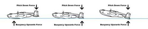
(Here: "portly" is to mean broad beam, Sunderland-esque; "parasol" to be Catalina-esque; "slender" hull is Martin P5M Marlin-esque).
Refs:
1. Princess: www.fzt.haw-hamburg.de/pers/Scholz/dglr/hh/text_2010_06_03_SR_Princess.pdf, fr. page 51. RAF page 173.
2. Buttler/Bombers,2004, P.143: portly twin-fin, dorsal turret "VS T.524, early-1949"
3. Flight cover, 26/2/54: the same image, no dorsal turret: "Saro Ocean Patrol Concept" (elsewhere stated as Nomad/P.162)
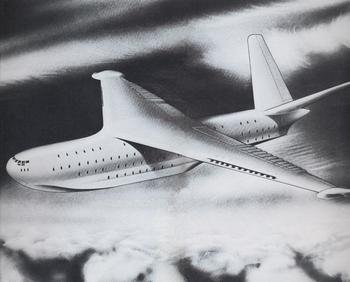
4. (CJG) Gibson/Nimrod Genesis, P.29, portly T-tail Saro P.162/6 (after 1951; wholly different to ref 3)
5. CJG/Nimrod Genesis, p.57, portly Short P.D.2, 7/49
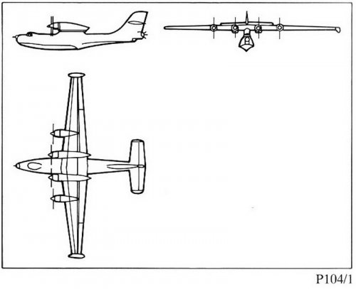
6. CJG/Nimrod Genesis, Pp.51/66: parasol P.D.2 (after 7/49), near-identical to:
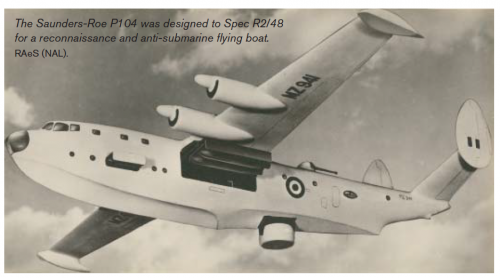
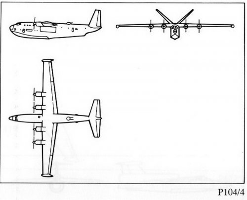
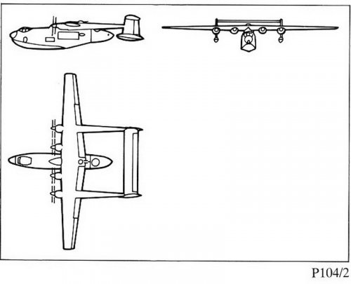
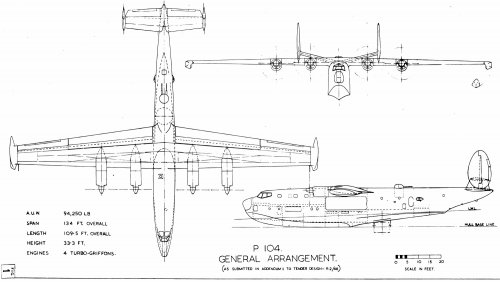
7. CJG/Nimrod Genesis,P.49: parasol Saro P.104/1 (5/49)
8. Robunos, here, Designation Systems: Saro: 14 P.104s dated 1948-53; P.162s 1952-56.

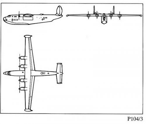
CJG/Nimrod Genesis, P.59
has R.4/48 Sunderland replacement "won" 7/49 by portly P.104/3; not funded; parasol P.D.2 funded "by 1950".

If
ref.2 is wrong (though it is credited to V-S historian E.Morgan) and is a P.162 (so later than early-1949); and if CJG, ref. 6, parasol P.D.2, is correct: then is this what happened?

A.Gouge
designs Shetland, 1942: he prefers portly boats; MAP imposes Saro (H.Knowler) to design the wing. MAP takesover Short, 23/3/43; Gouge to Saro: they scheme broad beams. Pay, 1945, to put big boats with vague markings on mag. covers. Why? UK was awash in Sunderlands (inc. straight from shop to chop), averse to Mariners, Coronados.

1/11/45 new Govt. policy: BSAAC to link UK-Argentina, happy to trade in £. 1945-50 UK will swap lots - retread Magister, Sandringham, heavens! even Prentice - for spam {yes, that's the word's origin}. Onway, more ports than airports. We need a big marine transport, even overlapping with Brabazon Committee's Type I 
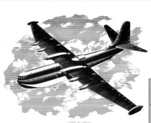
Transatlantic landplane (Bristol T.167). MAP Spec. 10/46 to tender. SR.45 funded 5/46, 1 prototype+3 for BSAAC. Portly. Traditionally built, broad in the beam.

UK, no MR interest - no enemy at sea. USN 6/46 funds the new notion of slender hull, by changing Mariner to Marlin. RAE thinks about it, Gouge/Knowler do not. CAS extracts funds, late-46, to supplement Sunderland G.R.V/Lancaster G.R.III with (to be) Shackleton M.R.1 (Tudor having failed, a prime candidate for any future Medium Bomber needed succour).

14/4/48: Cabinet declares USSR as world-wide Threat. Bombers, fighters awa'!...RAF marine MR Requirement out to tender; back 4/49 as portly T.524, P.D.2, P.104/3 - which, 7/49, is preferred (V-S busy, now, on (to be) Swift; V-A to help little Saro build boats apace)...ah, but...what about our empty SB&H/Sydenham. Pause for thought.

(By 1950) Saro's slender parasol P.104/1, Marlin-inspired (USN has more such slimlines in work), ah, inspires new P.D.2, MoS trickle-funded in design. BSAAC dies, 15/3/49; BOAC (for whom MCA orders 4 Princesses, 1948) by early-49 elects to abandon marine (so, 10/11/50). SR.45 should then have been aborted...but 1/1/50 new CAS MRAF Slessor had been AOC Coastal Command, 2/43-1/44. So, options open, SR.45 trickles on to flight 22/8/52, on MoS "Research" budget.

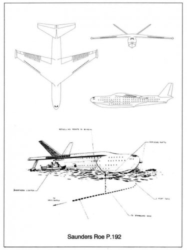
From 8/50, Korean War, UK basks in vast cascades of $, funding more Shackletons, loaning Neptunes. Saro pitches P.162s, Princess, Duchess variants 1952-54 to deaf ears until Cabinet, 14/1/55 says enough already, get on with Medium Bombers. Saro into DH, 9/56, Westland, 7/59 and Sir Arthur Gouge retires.
 
alertken,

I think that is about right but I would throw into the mix this succession of articles in Flight to add some context. The catalyst for the argument appears to have been the lack of support for flying boats from the Brabazon Committee.

Knowler The Case for the Flying Boat 25th Nov 1943
Pollitt Where Angels Fear 16th Dec 1943
Knowler The Case for the Flying Boat(2) 6th Jan 1944
Kemp The Future of the Flying Boat 27th Jan 1944
Gouge Flying Boats 10th Feb 1944
Pollitt The Flying Boat 24th Feb 1944
Gouge Flying Boat Morrings 3rd May 1945

All at http://www.flightglobal.com/pdfarchive/index.html
 
Ken, nice to see you're an early buyer! Thanks

Just seen your posts.

I'm doing this from memory. My take on the shenanigans is that Shorts got the R.2/48 job because the MoS wanted them to have it and happy to see Saro go down the pan. Shorts' problem as seen by the Air Staff was that they wanted a wide fuselage to take passengers and any boat they designed was designed for the civil market (later repeated with Britannic) Saro was deemed a better design than the Shorts, but lost out due to Govt shareholding in Shorts and need to keep employment in Belfast. The notion that Belfast was less vulnerable to Soviet attack than Cowes is risible.

Shorts initial portly PD.2 with nacelle weapons bays was laughed at by the Air Staff who told Shorts that if they were doing the job, they better do it right and sent them off to redesign the PD.2 - Parasol resulting.

By that time the flying boat had gone the way of the airship.

Anyone share any light on the lack of a Blackburn bid for R.2/48? That's listed in all the books but there is not even a mention of Blackburn in the R.2/48 files in Kew.

Also, OR.183 - Amphibious Air Sea Rescue type - The flying boat Catalina was acquired instead. Any idea why or was just the usual 'it was there and cheap'?

Must go - taxi at the door.

Chris
 
(Mods: humour us: not Secret but relevent background to schemes and dreams).

Blackburn post-war big boats: the Putnam, P.21 has the Board: "With reluctance, all work on marine projects was brought to an end and Maj.J.D.Rennie, the chief seaplane designer, resigned 5/46" (when his B-49 Clydesman lost to SR.45). So: surmise: its resurrection as scheme B-78 to R.4/48 was throttled when his rump team sought Co. budget to move up to a Tender brochure. Priority was on recovering from detritus of Firebrand and on coming second, with B-54, to Gannet.

Why Catalina? A.C Harris had been underwhelmed, being pitched the kitchen sink in US, 5/38. For GR/ASR we were well-suited with Interim Sunderland onway to definitive Lerwick, insured by B-20, but he acquiesced in 1 Model 28 for MAEE/Felixstowe (arrived, 7/39).
USN enhanced it as PBY-5, ordered 9/39, 40 for France, 12/39, by when...we knew we were not so well-suited. 30 (PBY-5) Catalina I were ordered (for cash money) 1/40 simply to secure some slots. Ditto RAAF, 18, 8/40, in preference to low priority if they ordered Sunderlands. Netherlands E.Indies AF ordered 36, 5/40: if they had thought of Sunderlands, they would also have seen slow delivery as an issue.

So, why, building Stranraers to 11/41, did Canada buy (to be) Canso, 9/40, first batch from US, then from Canadian-Vickers on end of Stranraer line; more from Boeing/Vancouver, 12/40. Some to be amphibs...but: endurance: Qantas would operate Perth-Ceylon, average sector of 27hr.
 
What ever happened with the Python? Did it ever find a production run elsewhere?
 

Attachments

  • Python_Gas_turbine.png
    Python_Gas_turbine.png
    1.2 MB · Views: 676
Back
Top Bottom