
You are using an out of date browser. It may not display this or other websites correctly.
You should upgrade or use an alternative browser.
You should upgrade or use an alternative browser.
OS-130: Competitors to the Vought F-8 Crusader
- Thread starter overscan (PaulMM)
- Start date
- Joined
- 17 May 2008
- Messages
- 702
- Reaction score
- 1,653
- Joined
- 27 December 2005
- Messages
- 18,727
- Reaction score
- 33,161
I decided to move Bill's post here, to the OS-130 topic.
- Joined
- 27 December 2005
- Messages
- 18,727
- Reaction score
- 33,161
As the Retromechanix Temco Model 31 article is no longer online, cached text here.
 web.archive.org
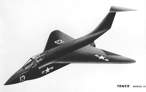
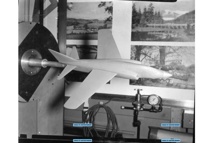
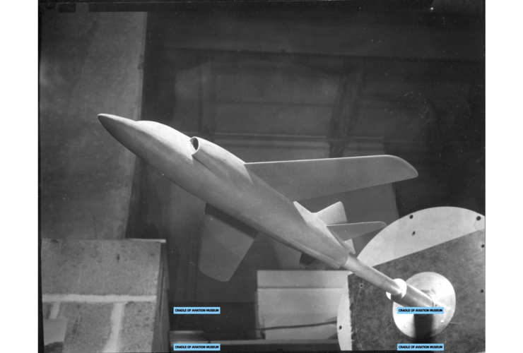
The TEMCO Model 31 was a Mach 1.25 VF Day Fighter designed to meet or exceed all performance requirements of BuAer outline Specification OS-130, as revised, while at the same time retaining the characteristics of simplicity and minimum weight—including use of an engine without afterburning—as called for in the original draft of the specification.
Minimum Aircraft Concept
TEMCO approached the entire problem of Day Fighter design from the standpoint of simplicity and minimum weight (minimum airplane concept) as called for in the original draft of Specification 130. By the time the change was made in the outline specification, shifting the emphasis to performance, and raising performance requirements, the company’s engineers had already done sufficient work on their original design to convince them that if the new performance requirements could be met while retaining the minimum airplane concept, the result would be an aircraft with marked advantages over one of similar performance but more complex design. A preliminary investigation was undertaken to determine the feasibility of meeting the new requirements within the minimum concept, and results were sufficiently favorable to warrant continuation of this approach. As the design developed, these preliminary conclusions were more than justified. It was found that by cleaning up the airplane to the utmost, it was not only possible to meet all performance requirements, but also that with a few additional improvements adding only slightly to complexity, it was possible to meet the specification in its entirety. As a result, TEMCO Aircraft proposed in its Model 31 a design which not only met Specification 130, but also because of its small dimensions and low weight offered such additional advantages as maximum maneuverability due to low degree of angular inertia; easy shipboard handling and maximum deck spotability; lower unit cost (assuming a fixed value for a pound of airframe), and greater reliability and lower maintenance costs due to the reductions in complexity.
Design Configuration
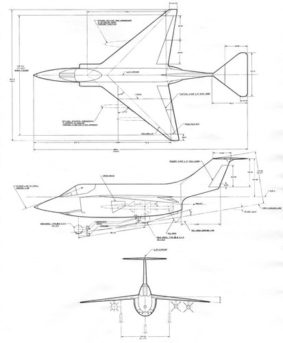
The TEMCO Model 31 combined a delta wing of a very low thickness over chord ratio (4.5 percent) with a relatively small conventional tail of the “T” type. The resulting configuration provided the structural and aerodynamic advantages of the delta wing while at the same time retaining the wider permissible CG range, higher maximum lift coefficient and better attitude control on take-off from runway or catapult, and better balance of the lateral/directional stability ratio over the full speed range of the aircraft which were inherent in a tail configuration. Another and even more significant result of the combined configuration was that it made possible the use of the NACA-16 series airfoil section. This series, originally designed as a supersonic propeller section, had a critical mach number 8 percent higher, a minimum drag coefficient 15% smaller, a maximum lift coefficient 5% higher and a lift curve slope 10% larger than any other conventional airfoil. The section had not been used prior to this time because of its relatively large trailing edge angle, but for thickness ratios of the magnitude of 4½%, the trailing edge angle was not only reasonable but had many advantages structurally and dynamically. Further with its higher lift coefficient and higher critical Mach number, the buffet limitations of the wing were improved and together with the comparatively light wing loading, the buffet boundary calculated to be much superior to any existing aircraft. Because of its high lift coefficient no high lift devices other than ordinary flaps were required for obtaining a reasonable landing speed.
The Model 31 airplane met and exceeded all the performance requirements outlined in Specification 130. In addition there was margin for covering contingencies which could have come up at a later date. Using military power, which was rated for 30 minutes, the airplane had a high speed of Mach1.25 at 35,000 feet and a combat ceiling of 53,500 feet. Its rate of climb was considered outstanding, calculated to be 20,000 ft/min stabilized at sea level combat weight. One of its unusual features was the relatively high cruising speed to and from the target area reaching 600 knots at 52,000 feet. Also worthy of mention was that additional combat time was available with only a proportionately small reduction in range. When viewed from the carrier operations standpoint the Model 31 performance data showed it could be launched from the C-11 catapult without rotating to maintain altitude because of its comparatively light gross weight, the energy requirements were well within the capabilities of the launching equipment. By the same token the energy requirements for arrested landing fell well within the capabilities of the MK-7 arresting gear and the steep slope of the NACA-16 series airfoil section together with the light wing loading established an approach attitude that was well below the visibility angle of the pilot. The slow speed stability and the exceptionally well rounded stall characteristics of the Model 31 wing section tended to require only a minimum of pilot proficiency to accomplish carrier landings. As previously mentioned, the airplane calculated to have superior characteristics with reference to buffet boundary. Factors contributing to its superiority were:
Preliminary buffet boundary calculations indicated that at Mach 1 and above, buffeting would not be encountered within the structural limitations of the airplane. These curves were undoubtedly conservative particularly between Mach .9 and Mach 1 inasmuch as the method used in computing the buffet characteristics had been so proven by flight tests of existing aircraft.
- Extremely low thickness to chord ratio (4½% at root).
- Comparatively light wing loading, 53 lbs/ft² at take-off weight.
- The 8% higher critical Mach number of the airfoil section and the steep lift curve slope.
- Minimum wing distortion under stress, attributable to the delta wing configuration.
Power Plant
The TEMCO Model 31 was powered by a J57-P-JT-3N engine with the afterburner omitted (JT-3M) in accordance with TEMCO’s adherence to the minimum airplane concept. Exclusion of afterburning eliminated weight and complexity, reduced fuel load required for a given mission by at least 50%, and added tremendously to future growth factor of the aircraft as will be discussed in more detail in the growth section further below. It should be noted here, however, that since the J-57 was an approved engine with afterburner, it was readily adaptable to an afterburner installation should performance in excess of the existing requirement be desired. The J-57 further suited the minimum airplane concept in that it is a two spool engine with windmilling capabilities down to and below the stall speed of the airplane, thus making it possible to reduce the requirement for standby systems and further lower the complexity factor.
Growth Factors
Even though the TEMCO Model 31 was designed in accordance with the minimum airplane concept, growth possibilities were not forgotten nor were they excluded. For instance, if in the future it should become desirable to obtain the maximum in performance at the expense of complexity the afterburner could be added to the engine without increasing the original dimensions of the airplane. Under the maximum performance concept external fuel tanks could be hung from the pylons already provided and dropped at the point of combat to preclude any drag penalty. Based then only on the attendant weight increase the maximum speed goes to very high limits. At 35,000 ft using augmentation the maximum speed increased to Mach 1.83. It was by necessity that the wing was designed for this speed potential originally in order to keep the drag rise well outside the limits required for the non-afterburning performance.
The landing speed would, of course, have increased with the installation of the afterburner even though the external tanks were dropped at point of combat. The increment of increase would have been consistent with the weight of the afterburner plus the additional equipment and shrouding, a total of approximately 1,500 lbs. If flight tests proved this increase to be outside the scope of pilot proficiency for carrier landings, slats could have been installed to reduce the landing speed to its original range.
Another potential growth factor lay in the possibility of adding elevators of 20% chord, which operated differentially, to the movable portion of the horizontal tail. By the use of the differentially operated elevators in place of the ailerons, the rolling pullout characteristics of the airplane could be improved considerably. The high location of the horizontal tail increased the effectiveness of the surfaces as ailerons to the point of providing rates of roll in excess of 220º per second at Mach 1 and better. By using the elevator surfaces alone, the buffet boundary in rolling pullouts could be made to approach that for symmetrical flight conditions. This system was not incorporated in the basic proposal because of the unknown dynamics factors involved. Sufficient time was not available to conduct a dynamic analysis of this configuration to determine its structural and dynamic feasability.
There had been much discussion in the industry with regard to contractor-furnished equipment and in this connection an investigation was conducted by TEMCO in conjunction with the Texas Instruments Corporation of Dallas, Texas, to determine the feasibility of an equivalent fire control system tailored to fit the Model 31 airplane. A proposal describing this installation is shown below. The primary advantages indicated were space, weight and reduced maintenance time.
As a result of an investigation conducted with the view towards determining future weight reduction potential of the airplane, it was found that the cockpit lighting comprised a sizable portion of the empty weight. TEMCO, of course, was not in any position to estimate, nor recommend, possible relaxations in the lighting requirements of Day Fighter Aircraft, however, if it should ever become possible to bracket the use of such an airplane to the extent of requiring only emergency type cockpit lighting, the company pointed out that 100 to 150 lbs weight could be saved.
Producibility
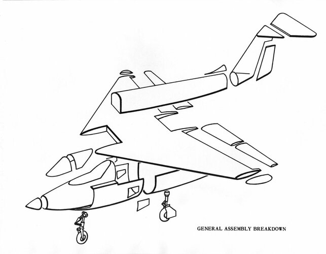
The very size of the Model 31 airplane was an indication of its adaptability to production in large numbers by virtue of its low airframe weight. The general assembly breakdown, as shown in the slideshow below, was felt to be adequate from an access standpoint and for major subassembly purposes.
Only a few large forgings were employed in the airplane, one left and one right main gear drag truss members, one at each end of the two engine mounting stations and one tying the horizontal stabilizer stub to the vertical fin.
Wing—Due to its short span and low thickness ratio, the wing was designed to be fabricated in one piece, extending from wing fold to wing fold being continuous through the fuselage. Jigging required for interchangeability was held to a minimum by attaching to the fuselage with vertical bolts extending through the wing in oversized holes. The wing leading edge was casting two halves and was bolted together, with light gauge skins bonded to the outer surfaces to produce the best possible aerodynamic smoothness. The leading edge was attached by piano hinge type fastening and was easily removed for access to controls and wiring. The wing tips, being folded by hand, automatically precluded a large number of machine parts with close tolerances. The movable surfaces, being piano type hinges, precluded the necessity for many castings and resulting close tolerance machining.
Fuselage—The fuselage was broken down into four sections, the upper, lower, forward, and nose sections. The main structural back bone of the forward section was the inlet ducts. By the use of structural ducts, the side panels could be removed, giving access to much equipment which was located adjacent to outside of the ducts. The inner fuselage section consisted of an engine pod which was readily removeable from the wing and forward fuselage section. Access to the forward fuselage from the inside could be gained through this opening.The upper part of the fuselage was of double skin construction plastically bonded to hat sections extending radially between the sheets. The fuel cells were of the bladder type which could be folded and installed through access holes in the top of the upper fuselage section.
Empennage—The vertical tail was conventionally constructed and was assembled at a production break point. The horizontal stabilizer, being only a small portion of the horizontal tail, was fabricated integrally with the vertical fin to reduce deflection and eliminate heavy fittings with attendant close tolerance. The movable portion of the horizontal surface was fabricated in one piece for the same reason.
Materials
Aluminum alloys formed the major portion of the airframe, 14S being used to small extent for very large forgings with 24S constituting 75% of all other materials used. 75S would be used for the major part of the forgings and all0y 356 for all castings. Magnesium would receive only limited use (.4%) for internal items. Titanium and stainless steel would be used interchangeably for the engine shrouding and tail structure in the vicinity of the jet stream, the exact application of each being dictated by its fabrication characteristics. Total of the two materials represented weightwise approximately 12% of the fuselage structure.
Centrifugal type castings with 7% minimum elongation were contemplated for use in the wing leading edge, wing tips, and wing tip trailing edge. Plastic type bonding metal t0 metal was planned for the area around the fuel cells and wing leading edge structure forward of the 20% line. Lockfoam plastic was considered for interior of wing tips and control surfaces to give reinforcement to skins handling damage.
Forgings were being employed in all sections of the airframe where simplification and structure by their use would give equal or greater strength about 15% of the structure. The pod area structure would be approximately 30% forgings which would include the engine points and tie-in of arresting gear. Two medium large forgings of thin section form part of the empennage structure. The landing gear would have one forging for the side brace which in the overall would be roughly 3½ x 26 x 40 inches. Honeycomb structure would be employed for wing panels outboard of station 100 to simplify internal structure and maintain aerodynamic smoothness.
Model 31 Structural Considerations
Wing—The planform of the Model 31 airplane wing was essentially a delta configuration, with low aspect ratio, high taper ratio, and 45º sweep back. The entire wing was assembled in one piece with all spars together with the major portion of the skin passing completely through the fuselage. Whenever possible, the spars followed the element lines of the wing, with all ribs being parallel to the air stream except in the neighborhood of the major gear attach point. Here the arrangement was altered to accommodate the folded strut and drag brace. Most of the bending moment due to gear loads was carried by a straight beam passing through and normal to the fuselage. This beam was extended outboard of the gear such that its intersection with the swept spar just forward of the gear attach points formed in effect an “A-frame”, thereby providing a rigid cradle for the landing gear.
Integrally stiffened skin, tapered wherever practical was used for covering on the inner panels. It was stressed not only in torsion, but also was utilized for bending. The skin, along with the spars, passed through the fuselage, and when assembled, acted as a part of the fuselage structure . Outboard of the gear attach point, where strength requirements are not so great but rigidity is still of prime importance for the cover skin, panels made up of aluminum honeycomb are used because of their flexural rigidity and smoothness of surface.
The only structural function of the leading edge was to transmit air loads and barrier-crash loads to the main part of the wing. The sharp contours necessary for the leading edge were obtained by utilizing a centrifugal casting process. The upper and lower surfaces were cast separately and aerodynamic smoothness was provided by stretching and bonding a relatively thin non-structural aluminum sheet over the “waffle-type” cast frame. The leading edge was attached by “piano hinge” fastening and was made removable in order to provide access to control systems, wiring, etc.
Both ailerons and flaps were “piano-hinged” to the trailing edge of the wing, and acted as simple flaps, having no mass-balance or aerodynamic balance. The conventional spar and rib structure was used.
The wing fold was located immediately outboard of the aileron and was parallel to the air stream. The folding mechanism allowed one man to manually unlock, fold, and lock in position the tip within 10 seconds. When the tip was extended, there were four attach points, thus providing structural continuity. Both leading and trailing edges of the tip were cast so as to provide attachment for spars and ribs. Extra rigidity was obtained by completely filling between skins with Lockfoam.
In order to obtain a design which combined aerodynamic smoothness, ease of assembly, and structural efficiency, TEMCO used castings, integrally stiffened skin, sandwich construction, metal bonding and plastic fillers wherever applicable.
Fuselage—The structural analysis of the fuselage had been broken down into three sections. The forward area extended from the nose to F.S. 190 and included the cockpit, canopy nose wheel well, guns, and engine air intake ducting. The shoulder height wing was continuous through the fuselage at W.L. 100 and was used as the break line for the remaining sections. The area over the wing contained the fuel bay which extended from F.S. 190 to F.S. 405. Below the wing and aft of F.S. 190 was the third section of fuselage. This portion provided for the speed brakes, rocket pod, main gear wheels, catapult fittings, tail bumper, arresting hook, and engine.
Forward Fuselage—The pilot’s enclosure was designed primarily for internal pressurization plus external air loads as occurring simultaneously. In addition to pressurization the flooring and bulkhead aft of the pilot’s seat was designed to carry seat loads for a crash condition. The transparent portion of the enclosure was supported around the edges by attachments to the fore and aft close out bulkheads and on the sides by the upper longerons. A ring frame supported the plexiglass and laminated glass windshield (center section) and also formed the front of clam shell arrangement of opening the enclosure.
The nose wheel well was approximately 75″ long. The vertical loads from the wheel went primarily to the forward bulkhead and then transferred to the outer fuselage skin with the remainder going to the aft bulkhead and to the fuselage skin. The fore and aft loads went primarily to the lower cap of the wall and from these caps to the fuselage skins. A portion of the fore and aft loads went to the enclosure floor and from there direct to the fuselage skin. The unbalance on the wheel well wall due to the distribution of the fore and aft load was balanced by a couple load into the fore and aft bulkheads. Side load was carried by forged frames just forward and aft of gear attach point. The torque from the gear produced by side load was taken into the well walls as differential bending going fore and aft to the bulkheads where it was carried to the fuselage skins. The fuselage had no torque box in the cockpit nose wheel area; therefore, the torque going to the forward bulkhead had to be carried aft by the fuselage skins as differential bending. The side load went into the forged frames which reacted the side load in the pilot’s floor and the lower fuselage skin. The side load in the pilot’s floor then distributed fore and aft to the closeout bulkheads of the enclosure and from there to the fuselage skins.
The engine air intake ducts were structural being made from skins having integral bulb stiffeners along their length. The integral stiffeners were closely spaced and machined off at frames to provide frame attachment to the duct. The duct was free and clear of internal support to provide an undisturbed airflow so frame spacing would provide support for the internal pressures both positive and negative in the duct. The frames that picked up the duct in the cockpit area were comparatively heavy to provide support for the side walls of the pilot’s enclosure and upper longeron as well as support for the duct. The duct picked up shear from the pilot’s floor and carried it down on the inside of the duct across the bottom and out to the fuselage skin in a shear panel between the bottom outer edge of the duct and the lower longeron. Since the duct was structural in its entirety, cap area for bending was maintained at the corners. The entrance or leading edge of the duct was a centrifugal permanent mold casting attached to a frame slightly aft of the leading edge. This would prevent denting or manufacturing roughness.
The radar and electrical equipment carried in the nose would produce loads that were carried in shear by the fuselage skin and in bending by an extension of the upper longeron and side cap members of a lower shelf back to the cockpit close out bulkhead where the bending loads were redistributed to the lower longeron. Access doors in this area forced most of the shear to go on the right side of the nose fuselage skin between bending caps. This created torque which was carried as differential bending between the upper longeron for one beam and the lower shelf cap for the other beam. The ditching loads would carry out in the same manner as equipment loads.
Upper Section of Fuselage—This portion of the fuselage break down was the most simple and straight forward. The entire area contained the fuel cells and the structure along its length was of necessity an arch. Main bulkheads located at the wing spars split the fuel area into four bays and supported the upper longerons. An additional “beefy” frame was used to pick up the rear engine mount loads and also to add support to the upper longerons which provided the longitudinal stiffness in this upper section. The upper longerons were also utilized as attaching members for the fuel tank access doors and the tank shrouds.
The arch structure below the longerons was sandwich skin with “hat” stiffening frames. The skins were bonded to the hat sections by the “Redux” process. All fuel access doors were structural and were adequately stiffened to support the fuel tanks in inverted flight maneuvers. Quickly removable access panels were provided in the structural doors to facilitate the adjusting and replacing of fuel gauges, and the disconnecting of vent lines. The bulkheads located at F .S. 190 and F.S. 405, as well as those at the wing spars, were capable of withstanding all fuel surge pressure loads due to catapulting and arrested landing.
Lower Section of Fuselage—There were three major discontinuities in this section of the fuselage; the rocket pod cut-out, the speed brake area, and the main landing gear wheel wells.
The rocket pod extended from F.S. 190 to F.S. 250 and across the entire width of the fuselage between the lower longerons. The rocket package was lowered in flight by means of a scissors mechanism located at the forward end and by dual actuators attached to F.S. 250 frame at the rear. The platform to which the rockets were attached was so designed that it could serve as the ammunition stowage area for the guns when the rockets were not installed.
The space between F .S. 190 and F .S. 250 above the lower longerons housed the speed brakes and the catapult bridle structure. The speed brakes were trapezoidal-shaped waffle type doors capable of carrying the air loads induced by their maximum opening of 60°. The catapult fitting back up structure provided the lower speed brake door sill as it was installed diagonally along the fuselage from the lower longeron at F.S. 216 to the forward engine mount located at F.S. 250 frame. Side load from the launching bridle was taken by the torque box bounded by the engine intake duct and the structural skin aboard of the speed brake door. A non-structural indentation in the fuselage to accommodate the main landing gear wheel was located between F.S. 285 and F.S. 315. The well height measures from the lower longeron up to the wing. Longeron support was provided by a structural access door below and between the longerons. This door allowed entry to the engine accessories.
Aft of F.S. 330 the lower longerons swung upward and formed a splice with the empennage lower longerons at F.S. 405. Auxiliary longerons continued horizontally, however, and provided the axial members to pick up the arresting hook and tail bumper loads. The fuselage skin aft of F.S. 329.6 frame was structural and aided in the rapid dissipation of these high loads.
The arresting gear pivot point was located at F.S. 372 with its attaching fittings tied to F.S. 369 frame. This frame was continuous around the entire fuselage periphery, and therefore picked up both vertical and side loads from the hook.
Tail bumper loads due to tail down landings were reacted by a canted ring which tied to the bulkhead at F.S. 405. Drag load was taken by the lower auxiliary longerons.
To expedite engine change, the entire lower fuselage pod was removable from F.S. 250 aft. Attaching flanges were provided on the major wing ribs at B.L. 30 and B.L. 19 with an additional member continuing aft of the wing to F.S. 405. A combination of shear pins, bolts, and hi-shear quick release (HSQR) fasteners were used to keep structural continuity through this removable shell under flight and landing loads. Access to the lower longeron ties at F.S. 250 was provided through the rocket pod opening. All vertical, drag, and side loads were reacted by the wing spars through the various load paths explained in detail above.
Empennage — The horizontal tail was of delta configuration and was attached to the upper extremity of the vertical fin. The very thin airfoil section of the horizontal tail precluded design of what was known as an “all flying tail”. However, by hinging the elevator at the 37.5% root chord point (from L .E.) the same results were obtained with a much more rigid structure. The small triangular stabilizer blanketed only a minor portion of the elevator and was built in as part of the fin through a large “T” forging at the rear spar intersections. The actuating mechanism for the horizontal tail was contained in the fin and tied into the movable portion of the horizontal tail aft of the hinge line.
The vertical tail was of conventional swept configuration with rudder hinge line at 76% chord. The vertical fin and a portion of the aft fuselage structure were built as a unit and spliced to the main fuselage structure at F.S. 405.
Horizontal Tail Structure —The movable portion of the horizontal tail made up a large percentage of the total horizontal tail area and, therefore, supplied most of the tail load. The structural configuration of the movable portion consisted of three main load-carrying spars running spanwise along constant percentage lines of chord plus a light closing spar near the leading edge to afford buckling restraint for the leading edge skin. The middle and rear spars were continuous to the horizontal tail centerline at which point they were spliced across the main centerline rib. The forward spar formed an intersection with the outboard hinge rib and the hinge fitting.
Rolled tapered skins were used in order that the most efficient strength-weight ratio was obtained. Local skin doublers were required in the center box area to provide for high shear concentrations.
The hinge loads were carried into the fixed stabilizer portion at three hinge points by means of a one piece fitting running spanwise between the two outboard hinge points. The third hinge point was at the centerline.
The movable surface hinge fitting attached to a forging in the fixed stabilizer which contained integral fittings for attaching the horizontal tail to the rear beam and tip rib of the vertical tail. Secondary attachments of the fixed stabilizer t0 the vertical tail were made at each of the other two vertical fin beams. Suitable structure in the fixed stabilizer was provided for taking air loads and local loads due to fitting eccentricities.
Vertical Tail Structure — The vertical tail structure consisted of three main structural spars plus light closing intercostals with stringers near the leading edge to provide buckling restraint for the leading edge skin. Stringers were also used between the spars to utilize the bending section more efficiently and to reduce panel sizes for delaying skin buckling. The upper portion of the rear spar picked up the main horizontal tail attachment and provided a bellcrank support point. The bellcrank was part of the actuating linkage for the movable portion of the horizontal tail.
The lower portion of the fin fuselage section was fabricated of titanium and stainless steel in areas adjacent to the jet stream as dictated by high temperature requirements. The rudder was of conventional one beam structure with chordwise ribs serving to break up the skin panels. It was hinged from the rear beam of the vertical fin at three points.
Landing Gear — The landing gear was of the tricycle type with air-oil shock struts. The main gear attached in the wing, and in retracted position was stowed in the wing and fuselage. The nose gear retracted aft to stow between the engine air ducts. During retraction the nose gear was compressed 70% and the main gear 74% of the total oleo stroke.
Design Considerations
Main Gear — In order to meet tread requirements the gear was pivoted from a point within the wing. The thinness of the wing however dictated fuselage stowage of the wheel and fork. The gear retracted inboard, and was jointed just above the fork so that the stowed wheel was in a vertical fore-and-aft plane, with wheel positioning provided by a spring loaded compression link.
Stroke requirements dictated a long gear, which was shrunk during retraction by a tension rodbetween a point in the wing and the three-piece scissor links on the oleo. A two-piece forged A-frame type member extended from the wing root to the gear at a point mid way between the gear attaching pivot and the static axle position. This A-frame acted as a side brace, and also provided fore and aft reactions to drag load. Thusly, gear drag loads were resolved into fore and aft loads on the A-frame and the wing, rather than into a torsional moment and fore and aft load on the wing alone.
During retraction and extension the hydraulic actuating cylinder drove from both ends. One end was attached to a bell crank on the upper A-frame (which also served as part of the retracting mechanism) and the other attached to a crank on the gear trunnion.
Nose Gear — The nose gear was provided with 24″ of oleo strut travel in order to reduce the vertical reaction during arrested landing to a value that would preclude the possibility of the main gear leaving the deck. Shrinkage during retraction was provided by the same type arrangement as that used on the main gear. The drag brace, which was also part of the retraction system, was attached just above the lower end of the outer oleo cylinder, and to the fuselage in the wheelwell aft of the gear pivot.
The remaining drawings of the TEMCO Model 31 are shown below as a slideshow.
While the Model 31 was a compact and elegant design, TEMCO appears to have erred in adhering so closely to the original version of OS-130, which called for a non-afterburning aircraft of minimum size, maximum carrier spottability, low gross weight, low initial cost, simplicity of concept, etc. In contrast, the revised version of the specification in November 1952 emphasized speed, rate of climb, combat ceiling and maneuverability, which necessitated a larger and more complex aircraft. TEMCO’s misreading of BuAer’s preferences resulted in a design that did not fulfill the Navy’s expectations, with no contract being awarded.
All images from NARA Archives II, College Park, MD, RG 72
Sources:
“TEMCO Model 31 VF Day Fighter,” February 1953, in the files of the National Archives at College Park, MD, RG 72
TEMCO Model 31 VF Day Fighter
Article reproducing TEMCO Model 31 VF fighter proposal designed to specification OS-130; includes high-res drawings & art.
web.archive.org
Last edited:
- Joined
- 17 May 2008
- Messages
- 702
- Reaction score
- 1,653
I decided to move Bill's post here, to the OS-130 topic.
Thank you. I will remember the guideline for future posts of like materials.
- Joined
- 27 December 2005
- Messages
- 18,727
- Reaction score
- 33,161
I decided to move Bill's post here, to the OS-130 topic.
Thank you. I will remember the guideline for future posts of like materials.
The model list topics are intended to just include information on models that existed and basic details. If you want to add more than just that, e.g. pictures or information, it should go in a an appropriate topic. Generally, a generic "all design to requirement x" type topic is good when there's not too much information on a design. If there's a lot on a specific design, it usually merits breaking out to a unique topic.
famvburg
I really should change my personal text
- Joined
- 24 July 2011
- Messages
- 386
- Reaction score
- 58
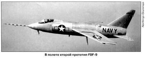
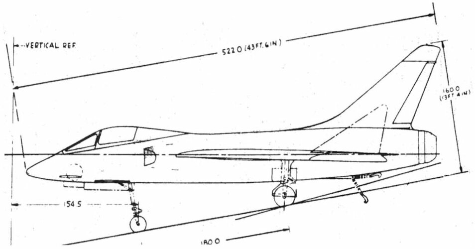
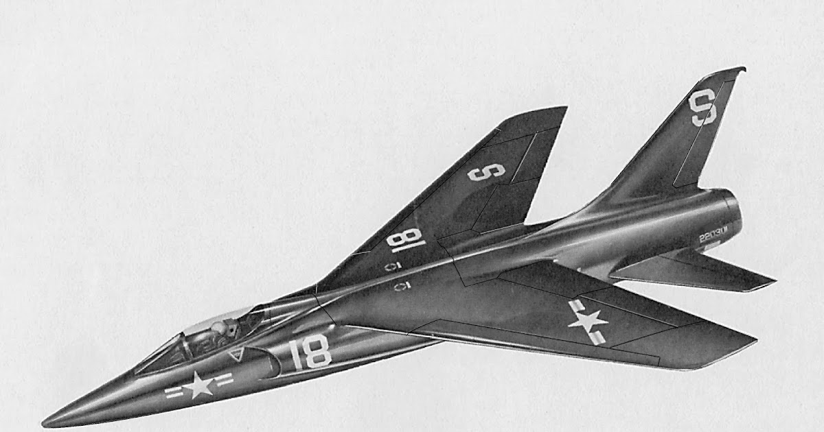
Later known as the F11F?From AiV 2020-1,
the Grumman F9F-8.
blackkite
Don't laugh, don't cry, don't even curse, but.....
- Joined
- 31 May 2007
- Messages
- 9,425
- Reaction score
- 9,299
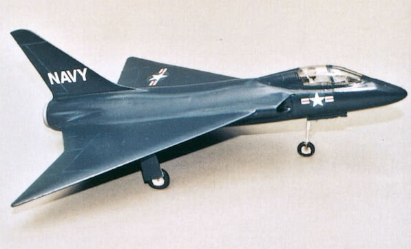
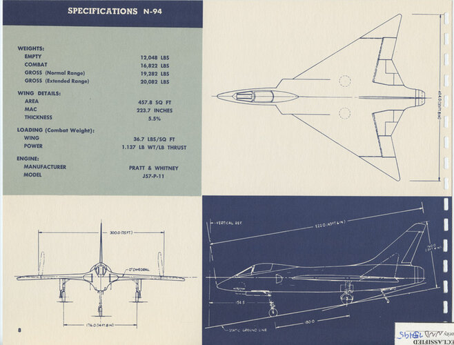
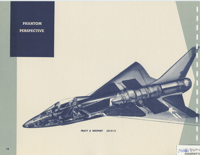
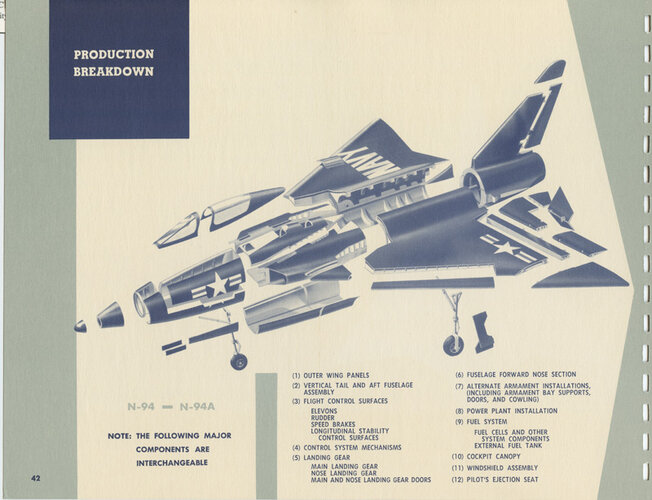
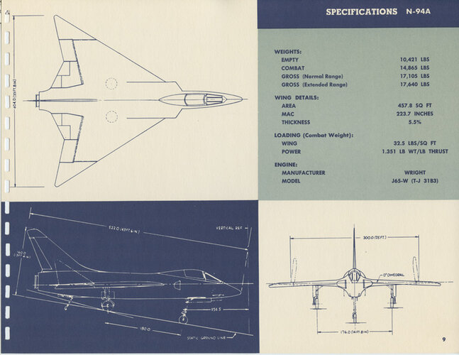
Hi! Northrop N-94.
http://aviadejavu.ru/Site/Crafts/Craft35131.htm
http://aviadejavu.ru/Site/Crafts/Craft35131.htm
Attachments
- Joined
- 26 May 2006
- Messages
- 37,579
- Reaction score
- 19,623
By the way,
Some of the rival designs to F-8 had three engines and many were
tailless or canard (tail-first).
I hope my dear Tony Buttler solve those mysteries in his new book,because we never
see any canard or three engined designs in the known competitors ?!.
famvburg
I really should change my personal text
- Joined
- 24 July 2011
- Messages
- 386
- Reaction score
- 58
Looks like a cross between an F4D and F7U!Hi! Northrop N-94.
http://aviadejavu.ru/Site/Crafts/Craft35131.htm
- Joined
- 17 May 2008
- Messages
- 702
- Reaction score
- 1,653
A few images from the NARA II files on the Northrop N94 and 94A.
General arrangements, phantom perspective and production breakdown.
General arrangements, phantom perspective and production breakdown.
Attachments
- Joined
- 17 May 2008
- Messages
- 702
- Reaction score
- 1,653
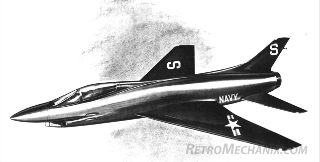
So there is no confusion or concern, I scanned Temco Report No. 31T.50.10 Summary Report Temco Model 31 Fighter at NARA II back in 2018. I wanted to say that because the report has the same language, might even be the same as post #125 in this topic that came from a web site. Attached are another view of the artist concept, size comparison with the F3H and a view of the fuselage structure.
Attachments
![Temco-Model-31-Size-vs-F3H-1-[NARA-Files].jpg](/data/attachments/198/198976-83e49b381433a72bbcc73d7308c7ac63.jpg)
![Temco-Model-31-Artist-Concept-Right-Rear-Overhead-View-[NARA-Files].jpg](/data/attachments/198/198975-9d2c27c249df005780cb22c7699f3302.jpg)
![z31T-930001-Temco-Model-31-Fuselage-Structure-Complete-(Proposal)-[NARA-Files].jpg](/data/attachments/198/198977-c6b46b7fd231b80b7a1768ca99fded34.jpg)
acegeek9992
ACCESS: Confidential
- Joined
- 25 March 2021
- Messages
- 111
- Reaction score
- 80
Tried accessing the link, it only redirects me to the homepage of the site.Stargazer2006 said:The Spangenberg Index gives all of these:
- Consolidated Vultee
- Consolidated Vultee (resubmit.)
- Douglas D-652/-1,-2, 652A ("F5D-2")
- Grumman G-97
- Grumman G-98 (?)
- Lockheed L-242/-1
- McDonnell 90
- McDonnell 91
- North American ESO 4927
- North American ESO 5197 Super Fury
- Northrop N-94/A/B/C
- Temco 31
- Vought V-383
- Vought V-384
The G-97 was the Grumman OS-130 competitor. The G-98 was the F9F-9/F11F Tiger. The North American Super Fury was a post-130 proposal that was an F-100B derivative. (see http://www.secretprojects.co.uk/forum/index.php/topic,9890.0/highlight,super+fury+f2j.html
acegeek9992
ACCESS: Confidential
- Joined
- 25 March 2021
- Messages
- 111
- Reaction score
- 80
Let me guess, is the fighter with the variable incidence wing the North American ESO 5197 and the F-100B lookalike the North American ESO 4927 Super Fury?Proposed Super Furies
F2J
The designation was never officially made by the Navy, but two North American proposals (three if you count the "FJ-5") could have resulted in an F2J. The first was in the OS-130 competition. Like the winning Vought design, it featured a two-position variable incidence wing.
George Spangenberg wrote that it came in a close second and lost primarily because North American projected that the gross weight of its J57-powered proposal was almost 30,000 lbs, considerably more than the Vought proposal's with the same engine. Spangenberg correctly predicted that the Vought weight was optimistic, but would still be less than the North American design and therefore provide better performance.
Thanks to Doug Siegfried at Hook magazine for the artist's concept and to Tony Buttler for the three-view. (Note: the three-view is the J65-powered proposal; like Vought and most of the other offerers, North American submitted both J65 and J57-powered proposals.)
In November 1953, North American tried to end run the F8U program with a Super Fury proposal, which was a carrier-based derivative of the J57-powered F-100B (stretched fuselage, wing flaps, etc.) being proposed to the Air Force. The F-100B was a redesign of the J57-powered F-100A that incorporated the latest supersonic flight technology and almost doubled the internal fuel capacity. The inlet was now swept back and incorporated variable geometry, with a horizontal ramp on the upper side used to establish and control the shock wave associated with supersonic flight. Unlike the F-100A, the fuselage was to be area ruled for improved transonic performance and lower supersonic drag. It had also been lengthened by almost four feet to increase its fineness ratio and add more fuel. The wing was basically the same in shape and area, but it was thinner and designed to hold fuel. Flaps were added and boundary layer control incorporated for slower takeoff and landing speeds. The main landing gear now featured dual wheels.
For the Super Fury proposal, in addition to adding the requisite tail hook, wing folding, catapult hooks, etc., other changes were made to the F-100B design to further improve the prospect of carrier suitability. When the flaps were lowered, the folding portion of the wings was repositioned to provide 15 degrees of anhedral to improve lateral stability and aileron control at low speeds. The fuselage speed brake was intended to be deployed on approach and would retract automatically on touchdown. Another innovation was a retractable gun sight to improve over the nose visibility.
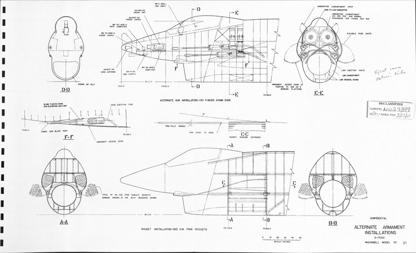
North American chose to propose armament of three T-160 20 mm cannons. Dual rotating rocket launchers contained 44 two-inch folding fin rockets could be substituted for the guns. One feature from the F-100B design was an alternative forward fuselage that incorporated a radome housing a small search radar in place of the APG-30 ranging radar.
Although it had the same engine and equipment, the Super Fury was heavier than Crusader so it would also have cost somewhat more. Although shorter, only 22 could be spotted in the requisite deck space compared to 25 F8Us . The Super Fury proposal was also deficient in military power ceiling. However, it was projected to be slightly better than just supersonic on military power, faster than required on combat power, have considerably more range on internal fuel and external fuel, and otherwise meet or exceed the requirements.
The proposal’s most compelling feature was that a prototype of sorts was flying and first Super Fury production delivery was expected in early 1956 on that basis. As it turned out, the Air Force decided not to proceed with the F-100B (although it did seque into the F-107) and the Vought F8U Crusader was a success.
FJ-5
Both Grumman and North American had previously gotten contracts from the Navy for new day fighters - the original F9F-8 (then F9F-9, then F11F-1) and FJ-4 respectively - using the funds provided to the F9F-6/7 and FJ-3 production contracts for product improvements. Both were powered by the Wright J65, the same as the FJ-3 and A4D. In accordance with the vision of the then Fighter Class Desk officer, the FJ-4 did not have an afterburner and was optimized for low cost of acquisition and operation. It was, however, to be a great dog fighter, with excellent maneuverability at altitude and near-sonic speed and did in fact achieve those goals. Grumman managed to get an afterburner on the F11F but it was a new Wright design and disappointed in thrust and therefore supersonic performance.
Against all comers, Vought had won the competitive day fighter contract in accordance with a new specification that required an afterburner. Both J65 and J57-powered designs were proposed, with the Navy selecting the higher performance J57 design. At this point, Grumman and to an even greater degree, North American, were in a disadvantageous position if the J57 turned out to be as good as expected and the Crusader met Vought's performance projections.
Both Grumman and North American then turned to the new General Electric J79 engine which was not available for the competitors to consider for the 1952 day fighter proposals in futile attempts to provide an attractive alternative to the F8U. Grumman apparently got to the Navy first and/or best, since BuAer began planning to buy a J79-powered F11F Super Tiger as the F12F. (One more time, the F12F was not the Grumman Design 118.) Unfortunately for Grumman, the XF8U went supersonic on its first flight in March 1955 and the F12F plan was dropped. However, BuAer did contract with Grumman for two J79-powered F11F-1Fs because they wanted to get some flight experience on the J79 before the F4H flew with it. Grumman was still hopeful that Vought would stumble with the F8U and/or the F11F-1F would be good enough to reinstate a Navy production program and/or be of interest to foreign buyers. North American's proposal didn't even get that far. Vought, of course, didn't stumble. The F8U was even faster than they guaranteed.
Strictly speaking, the "FJ-5" wasn't a navalized F-107, which was powered by the bigger J75. The FJ-5 had a gross weight of about 20,000 pounds and the F-107, 40,000 pounds. The two roughly compared like the Crusader I and the Crusader III. The FJ-5 had a bigger wing relative to its weight since it had to takeoff and land from aircraft carriers while the F-107, like the F-105, was to be flown from mile+ long runways. The designation doesn't appear to have been officially applied.
Proposed Super Furies
F2J The designation was never officially made by the Navy, but two North American proposals (three if you count the "FJ-5") could have resu...tailspintopics.blogspot.com
Last edited:
- Joined
- 17 May 2008
- Messages
- 702
- Reaction score
- 1,653
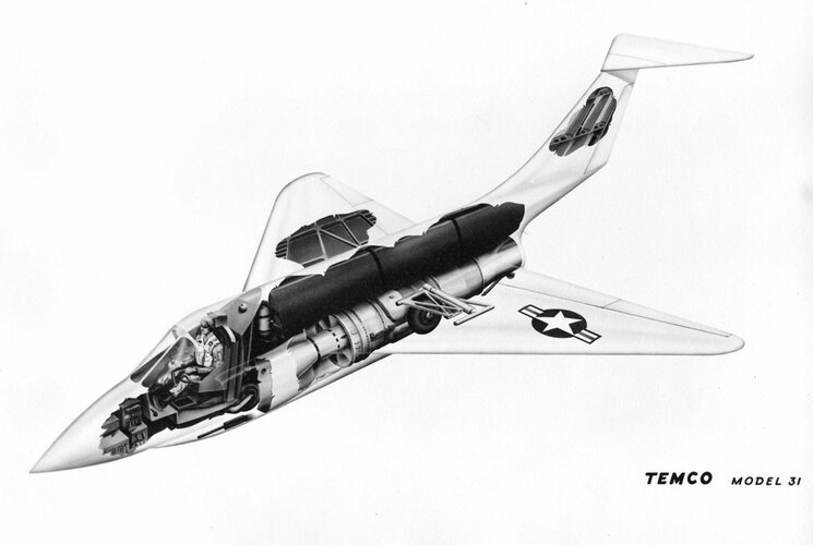
I found a couple more images I neglected to share in the original postings. Here is a cutaway view and a rough manufacturing breakdown for the T31.So there is no confusion or concern, I scanned Temco Report No. 31T.50.10 Summary Report Temco Model 31 Fighter at NARA II back in 2018. I wanted to say that because the report has the same language, might even be the same as post #125 in this topic that came from a web site. Attached are another view of the artist concept, size comparison with the F3H and a view of the fuselage structure.
Attachments
- Joined
- 27 December 2005
- Messages
- 18,727
- Reaction score
- 33,161
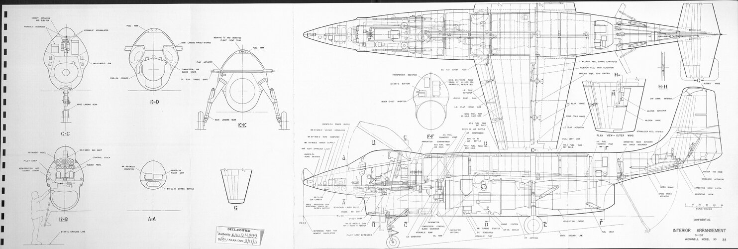
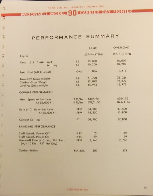
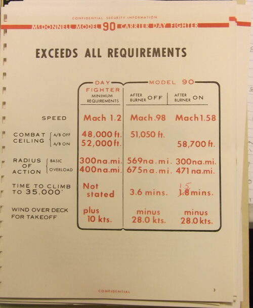
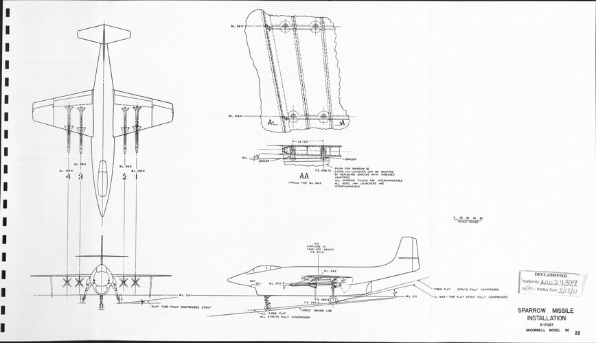
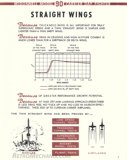
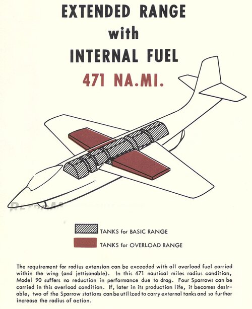
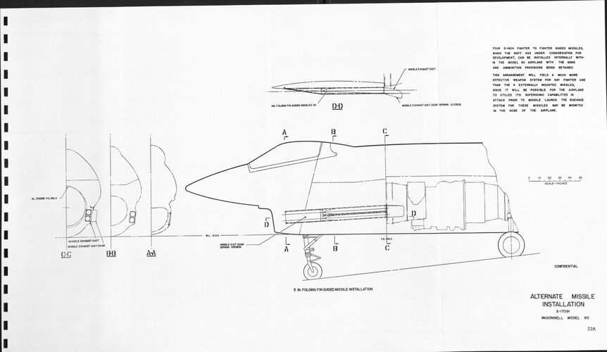
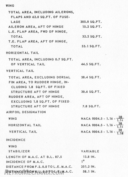
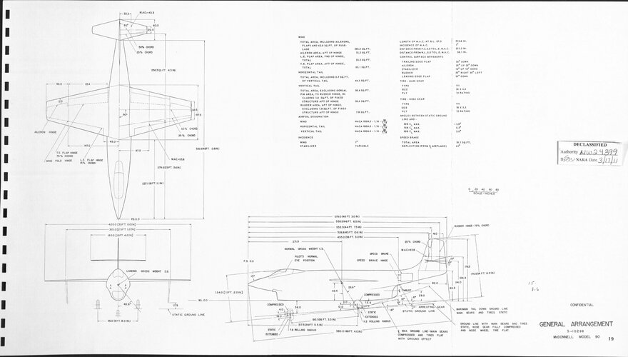
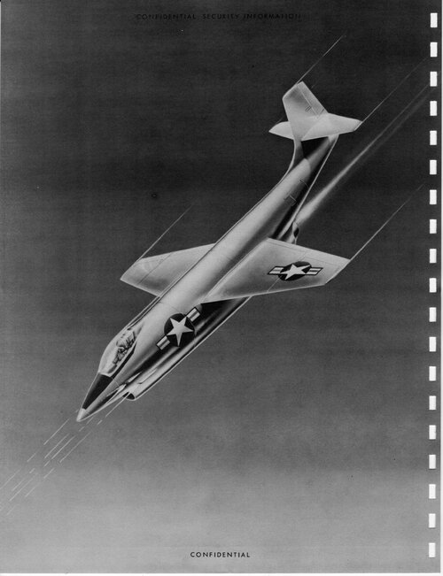
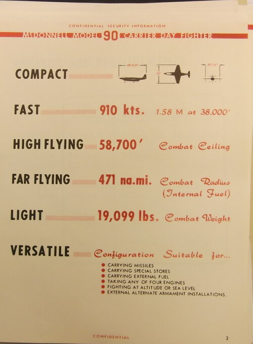
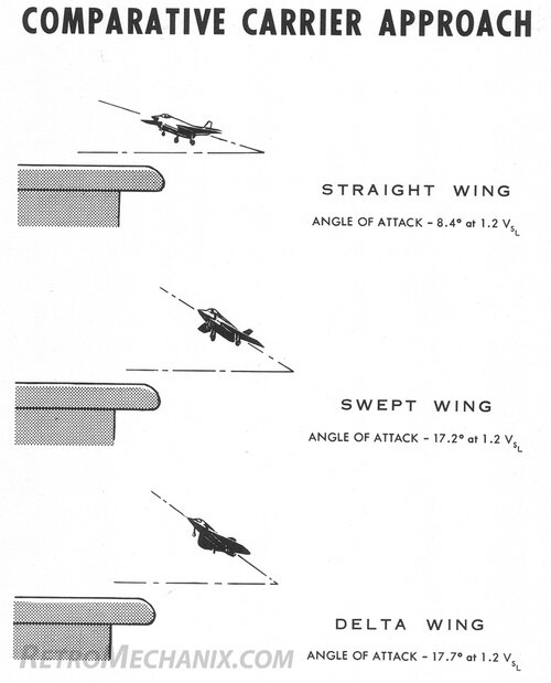
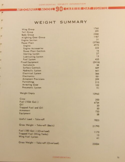
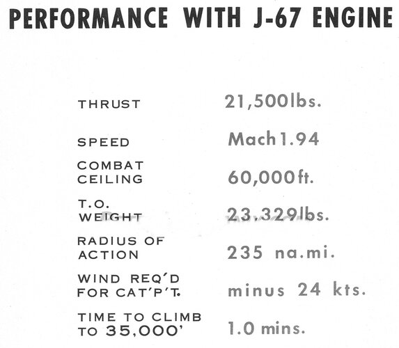
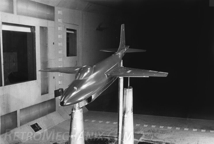
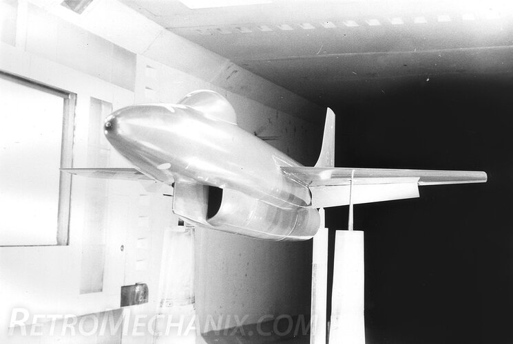
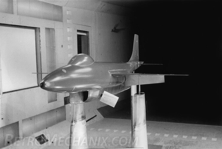
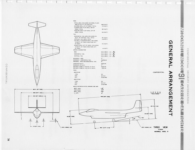
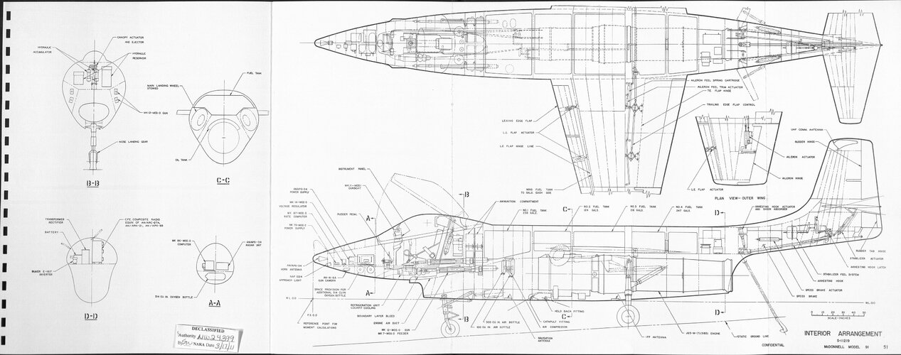
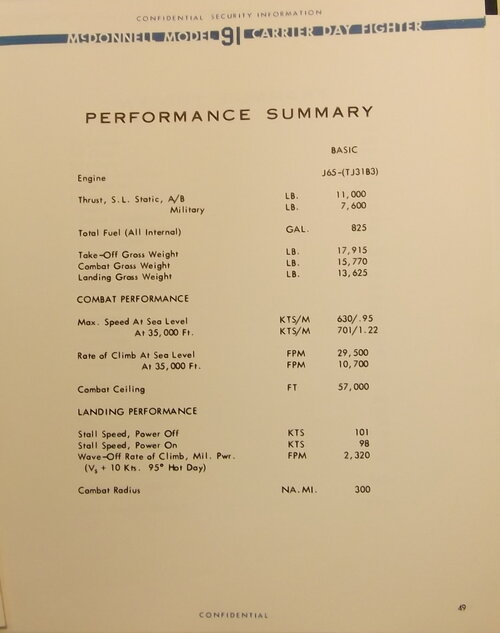
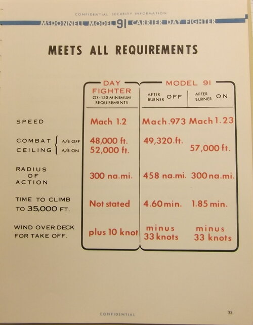
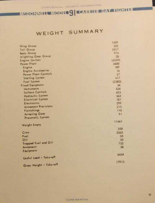
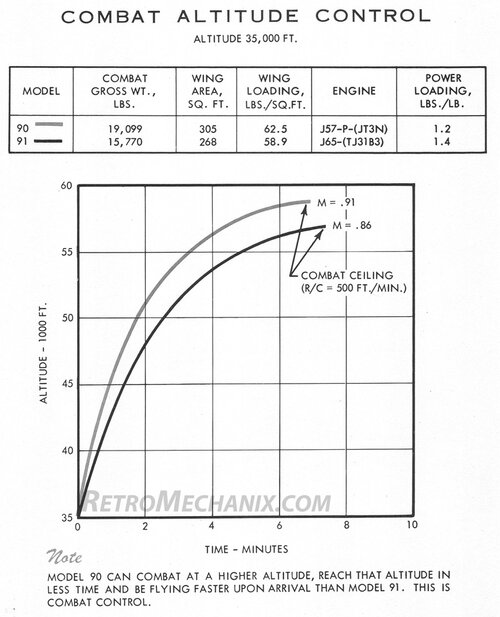
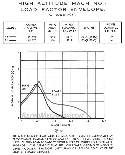
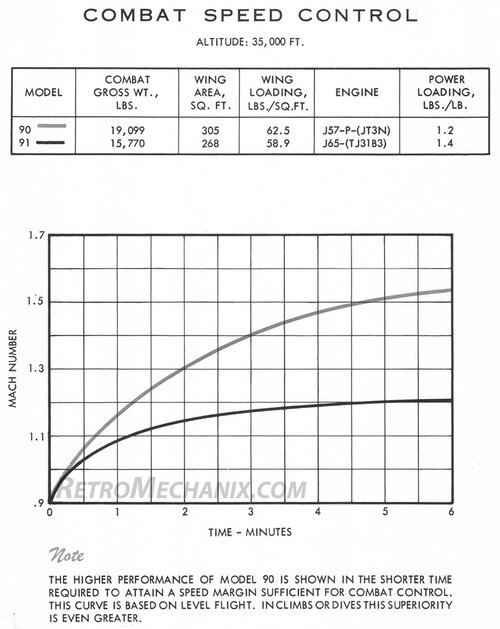
McDonnell Model 90 and 91 Brochure
Source: https://aviationarchives.blogspot.com/2024/01/mcdonnell-model-9091-carrier-day.html
Source: https://aviationarchives.blogspot.com/2024/01/mcdonnell-model-9091-carrier-day.html
Attachments
-
 Model 90 Inboard Profile.jpg1.8 MB · Views: 139
 -
 Model 90 Performance Summary.JPG211.1 KB · Views: 129
 -
 Model 90 Performance vs Requirements.JPG293.8 KB · Views: 112
 -
 Model 90 Performance vs Requirements.JPG293.8 KB · Views: 118
 -
 Model 90 Sparrows.jpg1.2 MB · Views: 125
 -
 Model 90 Straight Wings.jpg232.1 KB · Views: 117
 -
 Model 90 Fuel.jpg327.2 KB · Views: 110
 -
 Model 90 Folding Sidewinders.jpg1.5 MB · Views: 111
 -
 Model 90 Data-1.jpg233.9 KB · Views: 110
 -
 McDonnell 90 Cover.jpg1.4 MB · Views: 120
 -
 Model 90 3Vu.jpg1.2 MB · Views: 135
 -
 Model 90 Artists Concept.JPG3.3 MB · Views: 138
 -
 Model 90 Attributes.JPG337.4 KB · Views: 121
 -
 Model 90 cannon or rockets.jpg1.3 MB · Views: 108
 -
 Model 90 Carrier approach.jpg136.5 KB · Views: 101
Last edited:
- Joined
- 27 December 2005
- Messages
- 18,727
- Reaction score
- 33,161
Rest
Attachments
-
 Model 90 Weight Summary.JPG226.7 KB · Views: 90
 -
 Model 90 with J-67 Engine.jpg276.1 KB · Views: 88
 -
 Model 90 WTM-1.jpg538.6 KB · Views: 107
 -
 Model 90 WTM-2.jpg522.4 KB · Views: 116
 -
 Model 90 WTM-3.jpg471.8 KB · Views: 118
 -
 Model 91 3vu.JPG1.7 MB · Views: 126
 -
 Model 91 Inboard Profile.jpg1.5 MB · Views: 116
 -
 Model 91 Performance Summary.JPG237.3 KB · Views: 99
 -
 Model 91 Performance vs Requirements.JPG277.8 KB · Views: 79
 -
 Model 91 Weight Summary.JPG208.5 KB · Views: 76
 -
 Model 90 and 91 Altitude.jpg185.9 KB · Views: 73
 -
 Model 90 and 91 Performance.jpg178 KB · Views: 72
 -
 Model 90 and 91 Speeds.jpg179 KB · Views: 132
- Joined
- 26 May 2006
- Messages
- 37,579
- Reaction score
- 19,623
Attachments
- Joined
- 3 June 2006
- Messages
- 3,413
- Reaction score
- 5,646
Updated link:I've put up a short summary of the NAA All Weather Super Fury proposal of June 4, 1954 at RetroMechanix.com:

It features 78 high resolution images of the proposal brochure and subsequent "Growth Potential" report; it was quite a handsome design, I'm sure you will agree.
-Jared
North American All Weather Super Fury Proposal 1954 (150 DPI)
A pair of PDFs covering the North American All Weather Super Fury proposal of 1954, essentially a navalized F-100 featuring a prominent nose radome housing an AERO 11B fire control system with a variable-geometry chin inlet below it. The first document is a 64 page Design Summary from June 4...
- Joined
- 26 May 2006
- Messages
- 37,579
- Reaction score
- 19,623
By the way,
Some of the rival designs to F-8 had three engines and many were
tailless or canard (tail-first).
Afte all these years,I didn't see any three engines or a canard shape proposals ?.
Similar threads
-
-
 US Navy Outline Specification OS-112
- Started by Stargazer
- Replies: 23
-
US Navy OS-117 Outline Specification (S-2 Tracker rivals)
- Started by devi
- Replies: 161
-

-
General Dynamics and Vought Navalised F-16s to VFAX/NACF requirement
- Started by Mark Nankivil
- Replies: 86