To be honest, past AMRAAM usages have been misleading in terms of power parity between the AMRAAM user, most of the times USAF and USN CAWs, and its adversary. A more suitable example would be how many missiles were fired by each fighters of the IAF at Beqaa for example.To this day i think only 2 amraam have ever been fired by a single fighter.... sooo.... 6 v 5 really wasn't the deal maker for the usaf.

You are using an out of date browser. It may not display this or other websites correctly.
You should upgrade or use an alternative browser.
You should upgrade or use an alternative browser.
Northrop / McDonnell Douglas ATF - YF-23 and EMD F-23
- Thread starter Matej
- Start date
Interesting, but I suppose it's not hard to imagine that a launching mechanism for three missiles is considerably easier than one for two missiles especially when stacked vertically. In the end, it does seem that even though the F-23 bay has plenty of volume, the arrangement does make it less flexible for the current AMRAAM design.They share the same launcher.On the F-23, is the lower missile mounted on the door/hinge, or does it share the same launching mechanism as the top missile? When I say stacked, I meant that they're packed like a magazine where multiple missiles share the same launching mechanism. Contrast this to the current configuration on the F-35, where each missile has its own launcher. The middle missile on the F-22 has its own launcher, it's simply staggered in order for the fins to clear each other.

njiiaf
ACCESS: Confidential
- Joined
- 6 December 2021
- Messages
- 126
- Reaction score
- 378
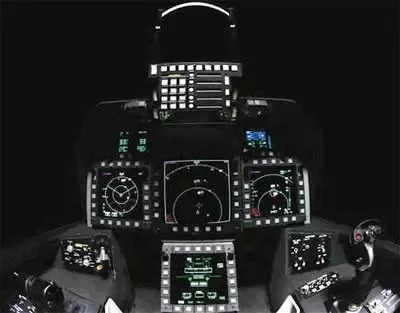
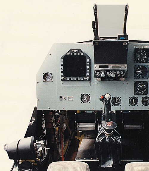
Does anyone happen to know what HUD and flight stick design the production F-23A would have used? Would they have just kept the F-15E style as on the prototype? None of the artwork really shows anything and both the F-22/F-35 used new designs even when off the shelf equipment would have been perfectly adequate.
The use of F-15E cockpit items for the YF-23 was solely meant to keep the costs of the prototypes down (more accurately technology demonstrators, as they’re arguably more like X-planes than true YF-planes). Had the F-23 been selected, it would have received an entirely new cockpit presumably with vendors that had yet to be competed and selected.
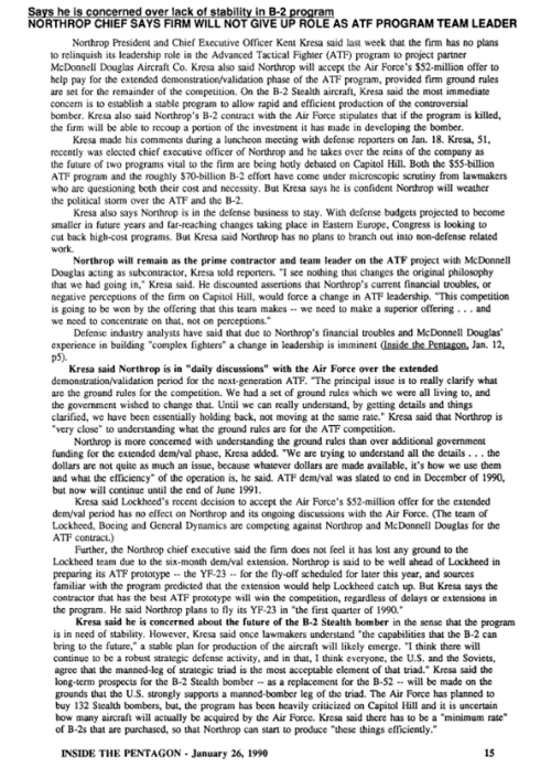
@Ogami musashi a few years ago found a DWG and concept art of one possible F-23 cockpit configuration, although this likely wasn’t finalized. Note the differences in HUD size, for instance.
@Ogami musashi a few years ago found a DWG and concept art of one possible F-23 cockpit configuration, although this likely wasn’t finalized. Note the differences in HUD size, for instance.
Microsoft OneDrive
onedrive.live.com
Microsoft OneDrive
- Joined
- 22 October 2006
- Messages
- 338
- Reaction score
- 76
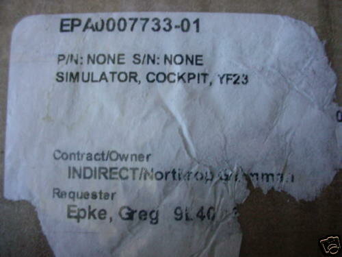
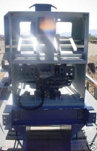
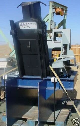
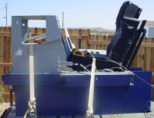
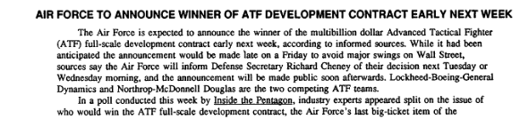
I don't get what is your message? The DWG is from the final proposal Northrop submitted to the USAF. The other one is not a art concept, it is a picture a F-23A cockpit in Northrop's simulator, circa 1990. The DWG is the most recent of the two.The use of F-15E cockpit items for the YF-23 was solely meant to keep the costs of the prototypes down (more accurately technology demonstrators, as they’re arguably more like X-planes than true YF-planes). Had the F-23 been selected, it would have received an entirely new cockpit presumably with vendors that had yet to be competed and selected.
@Ogami musashi a few years ago found a DWG and concept art of one possible F-23 cockpit configuration, although this likely wasn’t finalized. Note the differences in HUD size, for instance.
Microsoft OneDrive
Microsoft OneDrive
- Joined
- 27 December 2005
- Messages
- 17,748
- Reaction score
- 26,407
YF-23 Team Sees Savings in Switching From Distributed to Integrated Processor
Northrop and McDonnell Douglas will propose an integrated processor architecture for their YF-23 advanced tactical fighter, saving 50% in processor cost, weight and power compared to the distributed system originally planned.
The big surprise is the change back to an integrated processor. Distributed processors, capitalizing on “computer on a chip” technology, had been heralded as the architecture of the future. Originally the YF—23 team thought so, too, and was developing distributed processor systems. Increased combat survivability was a major reason for distributing systems throughout the aircraft, since a single hit would not be apt to cause critical damage.
In aircraft like the YF—23, where computers direct both the flight and engine controls, survivability of the computer and aircraft are likely to be synonymous.
SIX-FIGURE SAVINGS
However, while preparing to submit a full-scale development proposal, the Northrop/McDonnell Douglas team evaluated a number of trade-offs—commonly called trade studies. One effort examined the processor architecture and came up with a different answer—the integrated system which had been considered passe. The resulting savings will be in the six figure area for each aircraft, according to
Larry Nanney, mission avionics program manager for the YF-23 at McDonnell Douglas. Undoubtedly the savings were a big motivator, but increased performance of the integrated processor was also a factor.
The new technology that enabled greater performance at lower cost is Unisys’ advanced capability 32-bit General Purpose Processing Element (GPPE), Nanney said. The GPPEs are standard type B electronic modules. The YF-23 team will propose an architecture using one common signal processor, packaged in two core areas, with two 75-card racks. The two core areas will be separated for survivability, so that a single 40-min. shell would not destroy both, Nanney said.
The original distributed design, which was evaluated during ATF demonstration/ validation (dem/val), consisted of two common signal processors and three mission data processors. Each of the latter had three 1750 processors. Because they were not collocated, each processor required a module to interface with the data bus, and three power supplies for each mission data processor, The capacity of the integrated processor also will increase compared with the distributed system. The throughput capacity will be 20 million instructions per sec. (MIPS) instead of 2 MIPS. Further, with the new architecture the system will have a general purpose processing capability of 420 MIPS, and 6 billion operations per second of signal processing. Signal processors operate at higher speed than general purpose processors because each is tailored to a specific task.
During the demonstration/validation phase, the distributed system with 1750 processors handled only 2.5 MIPS, with contractors hoping for growth to 5 MIPS. The YF-23 will have 20 times the data processing and 87 times the signal processing
capacity of the F-15C. Nanney used the F-15C rather than the F-15E because the C is also an air-superiority aircraft. The ground attack mission adds memory requirements for the F-15E. “I’d be surprised if any tactical aircraft exceeds the E today since "it is the most recent upgrade in existing aircraft,” Nanney said. The YF-23 will have 17 times the data processing and 20 times the signal processing capability of the F-15E, he said.
There will be 15 different types of modules, with reliability predicted to range from 10,000 to 17,000 hr. The modules will use many very high—speed integrated circuits (VHSIC) chips. Typically between 10% and 15% of each chip is devoted to monitoring its own health.
Because of the predicted high reliability, the core signal processor will carry only one spare of each type of module.
The contractors demonstrated the advanced 32-bit general purpose processors in August. Faults were injected, and the system showed the ability to diagnose problems and reconfigure itself. The team’s response to the Air Force request for proposal (RFP) for full-scale
development of the ATF is due Jan. 2. Following evaluation of the proposals, the Air Force expects to select one team by
Apr. 30, 1991.
In preparing its proposal, the Northrop/ McDonnell Douglas team went through a number of risk reduction activities. They primarily addressed high risk / potentially high payoff items that fit in three categories:
* Trade studies.
* Avionics ground prototype demonstration.
* Flight test.
The team conducted about 103 major trade studies, including a host related to the core processing system. The change in architecture is one result. Other subjects considered included radome designs, whether to use active or passively scanned radars, and the Electro-
Optic Sensor System (EOSS). The Air Force decided that BOSS, which was actually an infrared search and track system, had not made sufficient progress to be included in the baseline aircraft (AW&ST Oct.1, p. 73).
The Northrop/McDonnell Douglas studies also resulted in the elimination of a sensor to detect lasers. Research showed there was only one laser threat in the world, Nanney said, which did not make the sensor cost effective.
The preponderance of avionics testing to date has been conducted in ground prototypes at Northrop’s Hawthorne, Calif, and McDonnell Douglas’ St. Louis, Mo., facilities. Nanney termed the tests in June and August the “final exams” for avionics in dem/val. In the June test, all sensors were operated in the modes that would put the most stress on the software. Threats were simulated and sent to signal and mission data processors as if they had come from the sensors. The August tests used in-flight sensor data to demonstrate the ability of the data fusion algorithm and the displays.
The YF-23 team conducted 103 avionicstest flights in a BAC-111 aircraft, accumulating 279 flight hours between July, 1989, and Sept. 12, 1990. Tests concentrated on the radar, electronic combat system and EOSS. The flight tests were particularly beneficial
for the Electronically Scanned Array (ESA) radar, produced by the Westinghouse and Texas Instruments team. McDonnell Douglas first flew the array in August, 1989. The hundreds of active transmit/receive modules give the radar the ability to rapidly transmit energy in different types of beams and multiple directions.
One concern that could be answered only in flight test was whether vibration and temperature changes would affect the coherence of the radiated signal. That problem and others were solved, stretching the ESA as far as the state of the art could accommodate, Nanney said. He predicts that the processing will stay state-of-the art until the turn of the century.
Reducing the pilot‘s workload has been a major goal of the YF-23 team. That effort has centered on processing and displaying the data so the pilot can spend his time planning his attack and flying the aircraft, rather than interpreting data. In the past, a multiple cathode ray tube (CRT) cockpit has dedicated one display to each sensor. The YF-23 team is taking a different tack and trying to integrate the data so the pilot could get the offensive information on one display and the defensive picture on another. The intent is to combine all attributes of a target, gathered from multiple sources, into one presentation. That takes a significant amount of processing, Nanney said.
To reduce the pilot’s workload, the team is attempting to develop intuitive display formats. The contractors will be working to improve
the data fusion throughout full—scale development. Thus far, they have integrated a Digital Equipment Corp. VAX computer, simulating 20 or more aircraft to stress the system. They also have used recorded in-flight data, but of a lesser number of aircraft.
The goal of increasing the pilot’s situational awareness will be aided by the combination of long-range, very-high accuracy sensors and a great improvement in processing capability. With an avionics suite operating in consonance with the stealth characteristics employed for a particular mission, the pilot should be able to detect and either engage or bypass an enemy before the YF-23 is detected,
according to Mike Major. He is Northrop’s manager of YF-23 operational mission objectives.
ESOTERIC CONCEPTS
To develop the integration, the Northrop/McDonnell Douglas team used a lot of man-in-the-loop simulation. Blue (friendly) pilots flew YF—23 simulators against red (enemy) pilots in MiG-29 and a next-generation threat aircraft. While the contractor provided most of the simulator pilots, the USAF’s Tactical Air Command sent a core group of pilots to act as a “sanity check.”
Some of the more esoteric display concepts, such as three-dimensional (3-D) displays and 3-D sound, were tried and rejected as not ready for operational use. The technology has developed sufficiently for 3-D displays, but the problem was that except for one situation, they were too hard to interpret, Major said.
Another idea being studied uses tactile stimulus to alert the pilot to high—payoff functions. The device being examined is a sleeve for the left arm. One extremely high payoff cue would help the pilot locate threats or targets in the quadrants behind him.
Systems for preventing g—induced loss of consciousness (gloc) in high—performance fighter aircraft have received increasing attention in the past few years. There are many ideas but no consensus on how a gloc system should be implemented, Major said. The ATF specification does not call for a gloc system. The YF-23 team has an assisted positive pressure breathing system that should increase the pilot’s ability to tolerate g forces.
There is a requirement for a ground collision avoidance system, which will warn the pilot to pull up, but will not take over control of the aircraft. To expand the capability to a pure gloc would require additional avionics, Major said.

Cockpit of a YF-23 is seen in an air-to-air engagement at the McDonnell Aircraft simulator in St. Louis. The displays were sanitized to protect presentation details.
Source: AWST 17 December 1990
- Joined
- 27 December 2005
- Messages
- 17,748
- Reaction score
- 26,407
The same cockpit layout was used in NATF cockpit artwork seen in Paul Metz's YF-23 book.
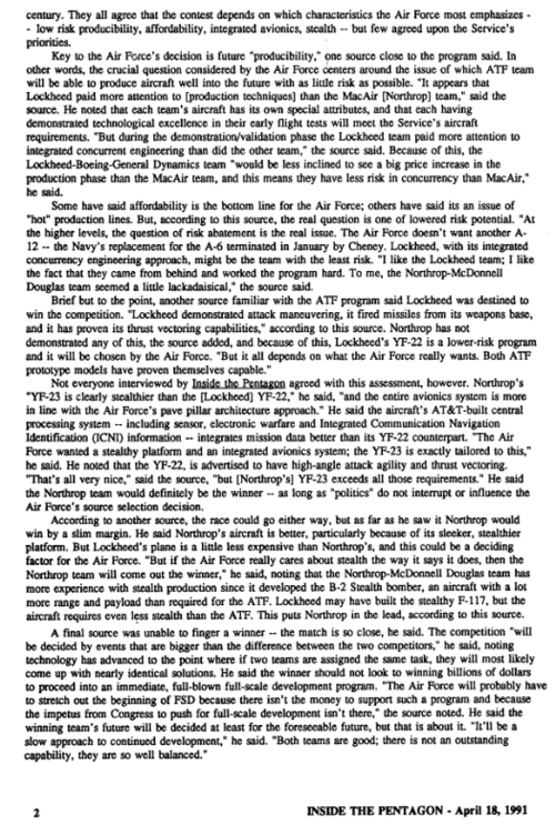
Here's a better copy of the simulator pic. You can just about make out the throttle and stick.

Here's a better copy of the simulator pic. You can just about make out the throttle and stick.

Last edited:
- Joined
- 1 April 2006
- Messages
- 11,390
- Reaction score
- 10,274
...
Attachments
-
 !BScm-lg!mk~$(KGrHgoH-CEEjlLly3cCBKDMc,thw!~~_12.JPG21.5 KB · Views: 212
 -
 2371_12.JPG25.8 KB · Views: 131
 -
 1bae_12.JPG28.7 KB · Views: 118
 -
 2713_12.JPG29 KB · Views: 120
 -
 !BSckgDgB2k~$(KGrHgoOKjoEjlLmRkbZBKDMPzdg!w~~_12.JPG37 KB · Views: 126
 -
 !BSckrYQ!mk~$(KGrHgoOKi8EjlLm(rUzBKDMQyI)l!~~_12.JPG21.8 KB · Views: 111
 -
 4241_12.JPG21.3 KB · Views: 107
 -
 !BSck7z!!mk~$(KGrHgoOKjkEjlLm,8SUBKDMSIF+zw~~_12.JPG21.2 KB · Views: 109
 -
 3f14_12.JPG21.2 KB · Views: 105
 -
 b6ee_12.JPG21 KB · Views: 99
 -
 !BScm6n!!2k~$(KGrHgoH-DIEjlLlul7eBKDMcHG1KQ~~_12.JPG19.9 KB · Views: 100
 -
 !BSck34!BGk~$(KGrHgoOKiMEjlLmVOYOBKDMR2BnHQ~~_12.JPG19.8 KB · Views: 107
njiiaf
ACCESS: Confidential
- Joined
- 6 December 2021
- Messages
- 126
- Reaction score
- 378
The same cockpit layout was used in NATF cockpit artwork seen in Paul Metz's YF-23 book.
Do you mean this?Here's a better copy of the simulator pic. You can just about make out the throttle and stick.

The reason I asked the original question is because the F-22 simulator looked like this at some point in the mid 90s
and this is obviously not the final design that went into production.
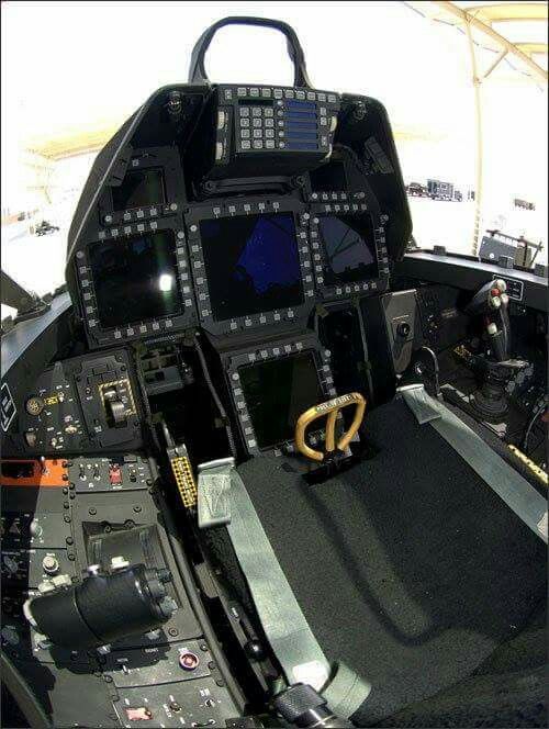
I was just wondering if anyone had any extra information. Thank you for the replies.
- Joined
- 28 January 2008
- Messages
- 1,016
- Reaction score
- 2,205
The ATF program also had a requirement for an advanced avionics architecture named Pave Pillar, Northrop was always big on evolving avionics on their on nickel. When I was at Northrop early on, I heard we exceeded the Pave Pillar requirements for ATF, Lockheed as far as I know from the early days of ATF and DemVal did not come close (I could be wrong), so this article has the linkage to Pave Pillar it seems. Example, the production F-23A would not have any external Pitot tubes, an all flush air data system do to LO requirements, like the B-2 and the B-21. The F-23A would have a highly integrated architecture. The YF-23 had a heck of a nice VMS suite which worked very well, at least from my perspective related to subsystems.YF-23 Team Sees Savings in Switching From Distributed to Integrated Processor
Northrop and McDonnell Douglas will propose an integrated processor architecture for their YF-23 advanced tactical fighter, saving 50% in processor cost, weight and power compared to the distributed system originally planned.
The big surprise is the change back to an integrated processor. Distributed processors, capitalizing on “computer on a chip” technology, had been heralded as the architecture of the future. Originally the YF—23 team thought so, too, and was developing distributed processor systems. Increased combat survivability was a major reason for distributing systems throughout the aircraft, since a single hit would not be apt to cause critical damage.
In aircraft like the YF—23, where computers direct both the flight and engine controls, survivability of the computer and aircraft are likely to be synonymous.
SIX-FIGURE SAVINGS
However, while preparing to submit a full-scale development proposal, the Northrop/McDonnell Douglas team evaluated a number of trade-offs—commonly called trade studies. One effort examined the processor architecture and came up with a different answer—the integrated system which had been considered passe. The resulting savings will be in the six figure area for each aircraft, according to
Larry Nanney, mission avionics program manager for the YF-23 at McDonnell Douglas. Undoubtedly the savings were a big motivator, but increased performance of the integrated processor was also a factor.
The new technology that enabled greater performance at lower cost is Unisys’ advanced capability 32-bit General Purpose Processing Element (GPPE), Nanney said. The GPPEs are standard type B electronic modules. The YF-23 team will propose an architecture using one common signal processor, packaged in two core areas, with two 75-card racks. The two core areas will be separated for survivability, so that a single 40-min. shell would not destroy both, Nanney said.
The original distributed design, which was evaluated during ATF demonstration/ validation (dem/val), consisted of two common signal processors and three mission data processors. Each of the latter had three 1750 processors. Because they were not collocated, each processor required a module to interface with the data bus, and three power supplies for each mission data processor, The capacity of the integrated processor also will increase compared with the distributed system. The throughput capacity will be 20 million instructions per sec. (MIPS) instead of 2 MIPS. Further, with the new architecture the system will have a general purpose processing capability of 420 MIPS, and 6 billion operations per second of signal processing. Signal processors operate at higher speed than general purpose processors because each is tailored to a specific task.
During the demonstration/validation phase, the distributed system with 1750 processors handled only 2.5 MIPS, with contractors hoping for growth to 5 MIPS. The YF-23 will have 20 times the data processing and 87 times the signal processing
capacity of the F-15C. Nanney used the F-15C rather than the F-15E because the C is also an air-superiority aircraft. The ground attack mission adds memory requirements for the F-15E. “I’d be surprised if any tactical aircraft exceeds the E today since "it is the most recent upgrade in existing aircraft,” Nanney said. The YF-23 will have 17 times the data processing and 20 times the signal processing capability of the F-15E, he said.
There will be 15 different types of modules, with reliability predicted to range from 10,000 to 17,000 hr. The modules will use many very high—speed integrated circuits (VHSIC) chips. Typically between 10% and 15% of each chip is devoted to monitoring its own health.
Because of the predicted high reliability, the core signal processor will carry only one spare of each type of module.
The contractors demonstrated the advanced 32-bit general purpose processors in August. Faults were injected, and the system showed the ability to diagnose problems and reconfigure itself. The team’s response to the Air Force request for proposal (RFP) for full-scale
development of the ATF is due Jan. 2. Following evaluation of the proposals, the Air Force expects to select one team by
Apr. 30, 1991.
In preparing its proposal, the Northrop/ McDonnell Douglas team went through a number of risk reduction activities. They primarily addressed high risk / potentially high payoff items that fit in three categories:
* Trade studies.
* Avionics ground prototype demonstration.
* Flight test.
The team conducted about 103 major trade studies, including a host related to the core processing system. The change in architecture is one result. Other subjects considered included radome designs, whether to use active or passively scanned radars, and the Electro-
Optic Sensor System (EOSS). The Air Force decided that BOSS, which was actually an infrared search and track system, had not made sufficient progress to be included in the baseline aircraft (AW&ST Oct.1, p. 73).
The Northrop/McDonnell Douglas studies also resulted in the elimination of a sensor to detect lasers. Research showed there was only one laser threat in the world, Nanney said, which did not make the sensor cost effective.
The preponderance of avionics testing to date has been conducted in ground prototypes at Northrop’s Hawthorne, Calif, and McDonnell Douglas’ St. Louis, Mo., facilities. Nanney termed the tests in June and August the “final exams” for avionics in dem/val. In the June test, all sensors were operated in the modes that would put the most stress on the software. Threats were simulated and sent to signal and mission data processors as if they had come from the sensors. The August tests used in-flight sensor data to demonstrate the ability of the data fusion algorithm and the displays.
The YF-23 team conducted 103 avionicstest flights in a BAC-111 aircraft, accumulating 279 flight hours between July, 1989, and Sept. 12, 1990. Tests concentrated on the radar, electronic combat system and EOSS. The flight tests were particularly beneficial
for the Electronically Scanned Array (ESA) radar, produced by the Westinghouse and Texas Instruments team. McDonnell Douglas first flew the array in August, 1989. The hundreds of active transmit/receive modules give the radar the ability to rapidly transmit energy in different types of beams and multiple directions.
One concern that could be answered only in flight test was whether vibration and temperature changes would affect the coherence of the radiated signal. That problem and others were solved, stretching the ESA as far as the state of the art could accommodate, Nanney said. He predicts that the processing will stay state-of-the art until the turn of the century.
Reducing the pilot‘s workload has been a major goal of the YF-23 team. That effort has centered on processing and displaying the data so the pilot can spend his time planning his attack and flying the aircraft, rather than interpreting data. In the past, a multiple cathode ray tube (CRT) cockpit has dedicated one display to each sensor. The YF-23 team is taking a different tack and trying to integrate the data so the pilot could get the offensive information on one display and the defensive picture on another. The intent is to combine all attributes of a target, gathered from multiple sources, into one presentation. That takes a significant amount of processing, Nanney said.
To reduce the pilot’s workload, the team is attempting to develop intuitive display formats. The contractors will be working to improve
the data fusion throughout full—scale development. Thus far, they have integrated a Digital Equipment Corp. VAX computer, simulating 20 or more aircraft to stress the system. They also have used recorded in-flight data, but of a lesser number of aircraft.
The goal of increasing the pilot’s situational awareness will be aided by the combination of long-range, very-high accuracy sensors and a great improvement in processing capability. With an avionics suite operating in consonance with the stealth characteristics employed for a particular mission, the pilot should be able to detect and either engage or bypass an enemy before the YF-23 is detected,
according to Mike Major. He is Northrop’s manager of YF-23 operational mission objectives.
ESOTERIC CONCEPTS
To develop the integration, the Northrop/McDonnell Douglas team used a lot of man-in-the-loop simulation. Blue (friendly) pilots flew YF—23 simulators against red (enemy) pilots in MiG-29 and a next-generation threat aircraft. While the contractor provided most of the simulator pilots, the USAF’s Tactical Air Command sent a core group of pilots to act as a “sanity check.”
Some of the more esoteric display concepts, such as three-dimensional (3-D) displays and 3-D sound, were tried and rejected as not ready for operational use. The technology has developed sufficiently for 3-D displays, but the problem was that except for one situation, they were too hard to interpret, Major said.
Another idea being studied uses tactile stimulus to alert the pilot to high—payoff functions. The device being examined is a sleeve for the left arm. One extremely high payoff cue would help the pilot locate threats or targets in the quadrants behind him.
Systems for preventing g—induced loss of consciousness (gloc) in high—performance fighter aircraft have received increasing attention in the past few years. There are many ideas but no consensus on how a gloc system should be implemented, Major said. The ATF specification does not call for a gloc system. The YF-23 team has an assisted positive pressure breathing system that should increase the pilot’s ability to tolerate g forces.
There is a requirement for a ground collision avoidance system, which will warn the pilot to pull up, but will not take over control of the aircraft. To expand the capability to a pure gloc would require additional avionics, Major said.
View attachment 691432
Cockpit of a YF-23 is seen in an air-to-air engagement at the McDonnell Aircraft simulator in St. Louis. The displays were sanitized to protect presentation details.
Source: AWST 17 December 1990

BDF
ACCESS: Secret
- Joined
- 14 March 2009
- Messages
- 284
- Reaction score
- 424
Yep. I've been corresponding with Aldo Spadoni who not only created the art work of the NATF over the carrier (as well as other pieces) but was also a avionics engineer for the F-23 team with Northrop. He worked on Avionics but not directly with cockpit systems. I asked specifically about HUD in the General Arrangement Drawings as you can see its clearly different from a F-15E HUD and also different from his art work and he told me it was just a notional design and not representative of what the production jet would have had. That being said, the artwork does match up with the GA Drawings that Steve posted in many ways.I don't get what is your message? The DWG is from the final proposal Northrop submitted to the USAF. The other one is not a art concept, it is a picture a F-23A cockpit in Northrop's simulator, circa 1990. The DWG is the most recent of the two.
I'm currently working on a F-23 related project and will share more details down the road when I'm getting close to releasing it. Sorry to be a bit of a tease!
BDF
ACCESS: Secret
- Joined
- 14 March 2009
- Messages
- 284
- Reaction score
- 424
This was the test sim where they trialed their ATF design against human flown RedFor threats. In the original AvWeek article it notes how the displays have been sanitized for essentially OpSec.The same cockpit layout was used in NATF cockpit artwork seen in Paul Metz's YF-23 book.
Here's a better copy of the simulator pic. You can just about make out the throttle and stick.
View attachment 691433
- Joined
- 1 April 2006
- Messages
- 11,390
- Reaction score
- 10,274
Where I've seen it before. Oh wait...
I mean, the congress even mandated that 3 concurrent defence programs were to be equipped with JIAWG architecture, although 2 of which were unfortunately soon dead. To be frank those claims makes me scratch my head a bit since JIAWG outlined the specific Common Avionics Baseline on which the ATF was also supposed to be built on, those including HSDB, VHSIC-based chips and so on. I'm not sure how Northrop could have such an edge against Lockheed in said situation. Also those DemVal avionics were soon rendered obsolete and experienced supply issues, was replaced with COTS parts anyways. I don't think there would have been such significant performance/capability difference between Lockheed CIP and whatever Northrop had and as I've said, those things on EMD aircraft were quite different to that of DemVal.The ATF program also had a requirement for an advanced avionics architecture named Pave Pillar, Northrop was always big on evolving avionics on their on nickel. When I was at Northrop early on, I heard we exceeded the Pave Pillar requirements for ATF, Lockheed as far as I know from the early days of ATF and DemVal did not come close (I could be wrong), so this article has the linkage to Pave Pillar it seems.
- Joined
- 28 January 2008
- Messages
- 1,016
- Reaction score
- 2,205
I was referring to a production F-23A and yes, the YF-23 took advantage of off-the shelf avionics and systems for the DemVal as any prototype/demonstrator program would have. However, the VMS as an example was new and designed for the DemVal aircraft along with the FBW flight control actuation system, all actuators were designed from scratch and procured specifically for the YF-23 application and would have moved right over into F-23A EMD and production phases. To my knowledge and again I could be wrong, Northrop had a more aggressive approach for an advanced fighter aircraft involving overall systems architecture as compared to Lockheed, at the time.I mean, the congress even mandated that 3 concurrent defence programs were to be equipped with JIAWG architecture, although 2 of which were unfortunately soon dead. To be frank those claims makes me scratch my head a bit since JIAWG outlined the specific Common Avionics Baseline on which the ATF was also supposed to be built on, those including HSDB, VHSIC-based chips and so on. I'm not sure how Northrop could have such an edge against Lockheed in said situation. Also those DemVal avionics were soon rendered obsolete and experienced supply issues, was replaced with COTS parts anyways. I don't think there would have been such significant performance/capability difference between Lockheed CIP and whatever Northrop had and as I've said, those things on EMD aircraft were quite different to that of DemVal.The ATF program also had a requirement for an advanced avionics architecture named Pave Pillar, Northrop was always big on evolving avionics on their on nickel. When I was at Northrop early on, I heard we exceeded the Pave Pillar requirements for ATF, Lockheed as far as I know from the early days of ATF and DemVal did not come close (I could be wrong), so this article has the linkage to Pave Pillar it seems.
Thanks for clarifying, I recall seeing images of the F-23 cockpit layout, but I wasn't sure how finalized those were. In any case, I was stating that it doesn't match the YF-23 because the latter is a technology demonstrator prototype that uses off-the-shelf components to rein in cost and schedule. Likewise, the actual vendors for components like the HUD, MFDs, may not be finalized by the time of EMD submission.I don't get what is your message? The DWG is from the final proposal Northrop submitted to the USAF. The other one is not a art concept, it is a picture a F-23A cockpit in Northrop's simulator, circa 1990. The DWG is the most recent of the two.
Well, VMS in both ATFs were separate from the main computer, in F-22's case the CIP, to my knowledge, so I'm not sure if mentioning VMS design and its bespoke component origins mean anything in terms of overall avionics architecture integration sophistication. What gets me puzzling is, again, how and in which way Northrop was more "aggressive"/"exceeding" compared to the baseline requirement from JIAWG and Lockheed's ATF avionics architecture for the reasons I've mentioned above. One thing I could think of for example is a higher level of RF integration, but that was only really materialized after JAST (Pave Pace) and with the given VHSIC/VHDL based signal processing structure I don't think you can go much further than what was already outlined by Pave Pillar/JIAWG.However, the VMS as an example was new and designed for the DemVal aircraft along with the FBW flight control actuation system, all actuators were designed from scratch and procured specifically for the YF-23 application and would have moved right over into F-23A EMD and production phases. To my knowledge and again I could be wrong, Northrop had a more aggressive approach for an advanced fighter aircraft involving overall systems architecture as compared to Lockheed, at the time.
Anyways, assuming that you're recalling things correctly, it's a very interesting information and topic, though I don't think we'll be able to find any relevant data any soon unless one gets to talk with the system engineering folks from Northrop during ATF.
aonestudio
I really should change my personal text
- Joined
- 11 March 2018
- Messages
- 2,964
- Reaction score
- 7,493
YF-23 Fans,
Robert R. "Bob" Sandusky Jr., Chief Engineer of the F-23 program, passed away in January. Here is a profile: https://www.aa.washington.edu/news/article/2023-02-16/aa-remembers-bob-sandusky
His tribute ceremony will be held at the Western Museum of Flight in Torrance, CA this weekend. Please see: https://www.wmof.com/
I worked very closely with Bob during his time consulting for DARPA's Experimental Spaceplane program ( https://doi.org/10.2514/6.2020-4205 ).
I would appreciate being able to reach the webmaster for YF-23.net (now https://yf-23.webs.com/ ) if any of you are able to put me in touch or have him/her PM me. The e-mail address listed on that web site bounces. That site played a very substantial role in putting me on a path to be able to work with Bob, who was the greatest mentor an aerospace engineer could have.
RIP Robert. He and his team created such an elegant plane that will never stop drawing an eye of any aerospace/aviation enthusiast that has the chance to see it, and for that I am thankful of him although he's not someone I know. Had I lived in the States I would've surely paid a visit to WMoF but since I can't, I really hope those who can will.YF-23 Fans,
Robert R. "Bob" Sandusky Jr., Chief Engineer of the F-23 program, passed away in January. Here is a profile: https://www.aa.washington.edu/news/article/2023-02-16/aa-remembers-bob-sandusky
His tribute ceremony will be held at the Western Museum of Flight in Torrance, CA this weekend. Please see: https://www.wmof.com/
I worked very closely with Bob during his time consulting for DARPA's Experimental Spaceplane program ( https://doi.org/10.2514/6.2020-4205 ).
I would appreciate being able to reach the webmaster for YF-23.net (now https://yf-23.webs.com/ ) if any of you are able to put me in touch or have him/her PM me. The e-mail address listed on that web site bounces. That site played a very substantial role in putting me on a path to be able to work with Bob, who was the greatest mentor an aerospace engineer could have.
Kerburettor
ACCESS: Restricted
- Joined
- 8 February 2021
- Messages
- 5
- Reaction score
- 9
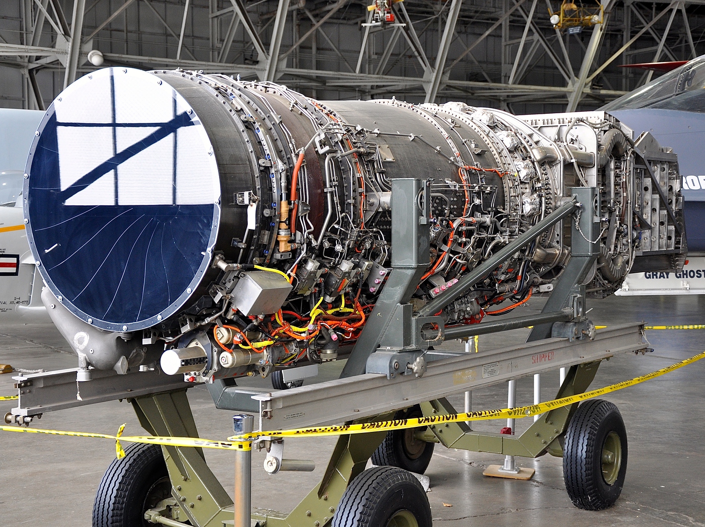
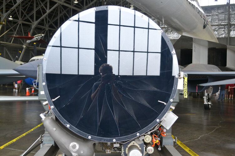
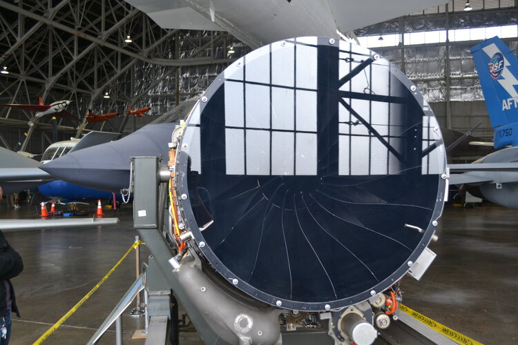
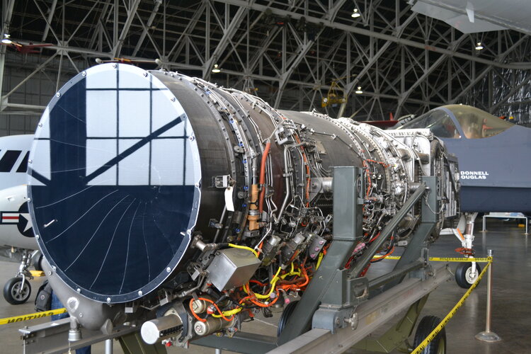
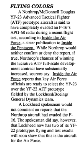
I see that the YF120 model exposed in the museum doesn't have inlet guide vanes. Beneath the protective glass, the fan blades are exposed to the incoming air which apparently does not always hit the blades at the right angle (from what I can see in the picture I included). Did they purposefully remove the section containing the vanes before displaying the prototype or was the flying version of the engine not supposed to have them? If it is the latter, what would be their rationale for not having inlet guide vanes?A really nice walk around the YF-23 on display at the National Museum of the USAF in Dayton Ohio.
Unless I am wrong and these are indeed IGVs? They do look like fan blades...
- Joined
- 1 April 2006
- Messages
- 11,390
- Reaction score
- 10,274
You are wrong. You can search for YF120 cross section on the forum to see how IGVs and fan blades look like.
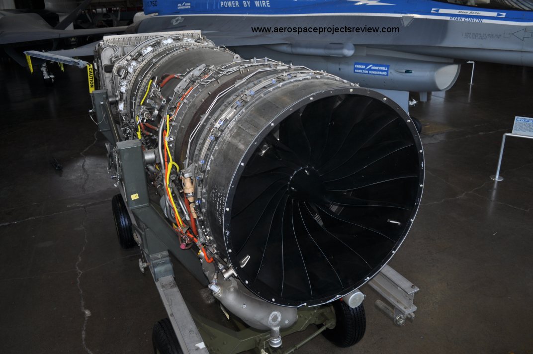
Photos (c) AJ Field
Photos (c) AJ Field
Attachments

Last edited:
Kerburettor
ACCESS: Restricted
- Joined
- 8 February 2021
- Messages
- 5
- Reaction score
- 9
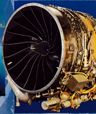
Ah yes, I found similar pictures on the up-ship blog just after I posted my question:You are wrong. You can search for YF120 cross section on the forum to see how IGVs and fan blades look like.
Photos (c) AJ Field
By the way can you direct me to the pictures of the cross-sections and images of the blades vs IGVs you were talking about? All I could find is conflicting diagrams which do not show the true shape of these components (although they do consistently show 3 fan stages, 5 compressor stages, etc.). I know it's classified data, but your message makes it seem like there are pictures I have missed despite a very thorough investigation on the internet!
- Joined
- 15 January 2021
- Messages
- 396
- Reaction score
- 1,455
The F120 had 2 stage fan on the low spool. There was a 3rd fan stage mounted on the front end of the core rotor, with 4 stages of high compressor behind that fan stage.
In high bypass configuration, air was sent into the bypass duct from the second stage fan, plus bypass air from the 3rd stage. This 3rd stage is running relatively unloaded with a variable vane running cambered in front of the blades.
In low bypass mode, the bypass from the 2nd stage was closed off, and the 3rd stage variable vane moved more axial to increase the blade loading, with the only bypass coming from the exit of the 3rd stage.
I don’t know how well the high bypass mode worked at saving fuel, but it burned much more fuel than the YF119 during supercruise. Maybe why it was so fast…
- Joined
- 1 April 2006
- Messages
- 11,390
- Reaction score
- 10,274
martinbayer
ACCESS: Top Secret
- Joined
- 6 January 2009
- Messages
- 3,397
- Reaction score
- 3,904
Not sure this is the best place, but here goes:

 www.thedrive.com
The Only Man Who Flew Both The F-22 And The YF-23 On Why The YF-23 Lost
Test Pilot Paul Metz gives an in-depth brief on the YF-23 and the Advanced Tactical Fighter program, including his thoughts on why the F-22 won.
www.thedrive.com
Last edited by a moderator:
Hoped it was something new but its basically an article about the Western Museum of Flight videos. It's quite remarkable how there are so many videos featuring Paul Metz regarding his experience with the YF-23, what anyone fond of the YF-23 should be grateful about.Not sure this is the best place, but here goes:
The Only Man Who Flew Both The F-22 And The YF-23 On Why The YF-23 Lost
Test Pilot Paul Metz gives an in-depth brief on the YF-23 and the Advanced Tactical Fighter program, including his thoughts on why the F-22 won.
- Joined
- 28 January 2008
- Messages
- 1,016
- Reaction score
- 2,205
I had worked with Paul off and on both on YF-23 and B-2. Lockheed did take more of a "marketing" approach on the YF-22 vs. the YF-23 according to Paul and Jim Sandberg. Our approach was purely from the engineering/performance viewpoint. Those big v-tails would allow us the same high AOA and low-speed/post stall maneuverability without thrust vectoring. We had our risks as well pushing new tech especially in the avionics area. Look at the new 6th gen concepts from other nations (even an LMCO concept), they smack of YF-23 baby! Again, we were 5.5+ generation.
There was another interview where Paul Metz regarded the YF-23 to be the finest handling airplane he has ever flown, even edging out the F-22 which he also spoke very highly of.Hoped it was something new but its basically an article about the Western Museum of Flight videos. It's quite remarkable how there are so many videos featuring Paul Metz regarding his experience with the YF-23, what anyone fond of the YF-23 should be grateful about.
In the end, the USAF would have had a fantastic aircraft regardless of which one was chosen, F-22 or F-23. They each had their advantages over one another but it wasn’t major or decisive. I think a lot of people were captivated by the YF-23’s exotic appearance and thus got carried away when describing its advantages to exaggerated extents. Ultimately, both were excellent designs, unlike some other programs where one entry was decisively superior to the others.
BDF
ACCESS: Secret
- Joined
- 14 March 2009
- Messages
- 284
- Reaction score
- 424
You encapsulate exactly my perspective on the program. From a pure aesthetic and emotional appeal, I wished the F-23 had won. But we did get a great airplane with the F-22 and I think it was a rare instance where both competitors were great airplanes and fully met the requirements. That interview with Rick Able on Mover's youtube channel is fascinating and I think his seemingly non-biased perspective of the program really bears this out. He clearly states each airplane had its strengths and weaknesses but would be, as he put it, "damn fine killing machines." I also believe that the official reason for the down select, as elucidated by the USAF, was more or less correct. It came really down the ability of teams to execute the program and unfortunately Northrop was going through a real rough patch with it's big programs.There was another interview where Paul Metz regarded the YF-23 to be the finest handling airplane he has ever flown, even edging out the F-22 which he also spoke very highly of.
In the end, the USAF would have had a fantastic aircraft regardless of which one was chosen, F-22 or F-23. They each had their advantages over one another but it wasn’t major or decisive. I think a lot of people were captivated by the YF-23’s exotic appearance and thus got carried away when describing its advantages to exaggerated extents. Ultimately, both were excellent designs, unlike some other programs where one entry was decisively superior to the others.
Motocar
I really should change my personal text
- Joined
- 16 May 2014
- Messages
- 1,081
- Reaction score
- 1,136
eitherHigh res copy here: http://www.secretprojects.co.uk/YF-23 4 View.gif (1.35mb)
I wish I could post this image again, I regret not having seen it, only the link no longer shows it.
- Joined
- 1 April 2006
- Messages
- 11,390
- Reaction score
- 10,274
Similar threads
-

-
 ASD Preliminary Designs in Splendid Vision, Unswerving Purpose
- Started by XP67_Moonbat
- Replies: 16
-
McDonnell-Douglas ATS, pre-ATF and ATF studies
- Started by flateric
- Replies: 174
-
McDonnell Douglas F101B Voodoo - carrying MIM-23 Hawk Missile
- Started by Jonathan338
- Replies: 11
-
 VFAX (1974) / NACF Projects (Pre F/A-18 concepts)
- Started by overscan (PaulMM)
- Replies: 53