North American Rockwell NA-335 fighter project (to USAF FX requirement)

Here's a North American Aviation (Los Angeles Division) concept model of an early F-X design with VG. Gotta love those fake afterburner flames!
Good Day All -

From the Gerald Balzer Collection - artwork that goes along with the model Circle-5 posted in #14 of this thread.

Enjoy the Day! Mark
 

Attachments

  • zNAA VG FX Concept Artwork.jpg
    zNAA VG FX Concept Artwork.jpg
    825.9 KB · Views: 1,319
Very cool. Wings are super stubby :)

znaa-vg-fx-concept-artwork-jpg.658595


naa-f-x-02-jpg.75724
 
sferrin said:
AAAdrone said:
Wonderful images! I really am surprised that the US didn't go with NAA's design really.
The Chief engineer at Sukhoi said something to the effect of the North American design being the one they were most worried about. (Though I'll be damned if I can remember where I read that. Might have been American Secret Projects - Fighters)


Source is Oleg Samolovich in "Next to Sukhoi", posted by me here a long time ago. He actually says, IIRC, "Northrop" which I assumed was a mistake for "North American" on his part but I believe Northrop were the major subcontractor on the NAA/Rockwell FX so maybe there's something more to it. I'll check my copy of the book.
When I googled the book it said its only available in Russian. Do you read Russian?
There must be some great books on Soviet aviation only available in Russian.
I don't read Russian, but if you scan a page or obtain a PDF or ebook copy of a book, you can use machine translation to turn it into readable English.


E.g. I bought Victor Markovsky and Igor Prikhodchenko's MiG-23 book as an EPub and translated using Google Translate.

Its pretty readable without any editing:


The production of the MiG-21, which was massively built at three plants at once, increased from year to year, amounting to more than 550 aircraft in 1963 (351 fighter aircraft delivered to Gorky Plant No. 21 and 200 - Moscow Plant No. 30, Tbilisi Plant No. 31 was engaged in the production of “sparks” "). The next year, 1964, the order increased to 720 fighters (420 plants number 21 and 300 - plant number 30). Constantly working on the machine, its creators made the necessary changes and improvements to the design and composition of airborne equipment and weapons.

However, along with the advantages, the MiG-21 as the main destroyer the concept of the combat properties of an aircraft, as applied to a fighter, implies a combination of its qualities and characteristics, such as the most important flight tactical data (maximum speed, climb rate, ceiling, maneuverability, range and duration of flight), armaments and equipment that allow destroying an air enemy. As determined by the Air Force tactics course, such a combination of combat properties was intended to provide the fighter with the opportunity to "quickly enter the combat zone, quickly catch up with the enemy and, using advantages in speed and maneuvering qualities, eliminate the tactical advantages of the enemy and achieve victory over him."

The MiG-21PF had flight characteristics at the level of a modern aircraft of this class: speed for two sound, a ceiling of 19,200 m, excellent rate of climb and maneuverability. The plane gained ten kilometers in just 2.7 minutes, and at low altitudes it was able to twist turns within a kilometer radius. The range characteristics looked somewhat worse (in which domestic fighters traditionally lagged behind competitors): the practical range of the MiG-21PF without suspensions was 1140 km, one and a half to two times inferior to Western aircraft of the same destination (the F-104G Starfighter has a range with a reserve fuel in internal tanks alone was 2,000 km, while the then-new F-4C Phantom II, even with a set of missile weapons, reached a range of 2,600 km).

As the changes were introduced, the "twenty- first" gained weight, which could not but affect the climb and even more "sagging" range. Attempts to add fuel reserves were unsuccessful, because the aircraft was heavy and the wing load was growing with attendant negative consequences. The low range resulted in limited boundaries of interception and radius of the aircraft during the entire set of tasks, and the duration of the flight, even with an outboard tank not exceeding 2.5 hours, reduced the ability of a fighter to cover ground troops or patrol a protected area. The maximum line of interception of the MiG-21PF using the PTB was determined to be 400-530 km, while the Starfighter with a set of missile weapons and hanging tanks was 120011 11 1430 km and the Phantom had 1820-1940 km. Meanwhile, the fuel supply on board the fighter was important not only in terms of range: the sufficient flight duration allowed the pilot to feel more confident when performing a combat mission, without the risk of being with dry tanks away from the airfield at the most critical moment.

The state of affairs with sighting equipment and aircraft weapons left much to be desired. The MiG-21PF was equipped with the RP-21 radar sight (another name TsD-30T, that is, the “target rangefinder”), which was believed to provide the fighter with “all-weather use and the possibility of reliable destruction of air targets at sufficiently large ranges day and night in simple and complex weather conditions." The capabilities of the radar station made it possible to detect an air target such as a Tu-16 bomber at a distance of 18-20 km with a capture for auto tracking from 8-10 km. The armament of the aircraft consisted of only two R-3S close combat missiles with thermal homing heads with a launch range of up to 7.6 km, instead of which RS-2US missiles with “beam-rider” guidance with a firing range of up to 6 km could be used. The RS-2US, guided by the beam of the radar operating in the target locking mode , could not be classified as a modern weapon: they allowed attacks to be carried out exclusively from the rear hemisphere of the target in the 1/4 perspective only with a slight speed excess of the target over their fighter (otherwise missiles lacked energy), in addition, after launch it was necessary to keep the radar beam on target throughout the entire flight of the rocket, avoiding any manoeuvring. The fighter’s equipment with RS-2US missiles was a necessary measure, since the self-guided R-3S as the main set of weapons did not provide all-weather use - it was indicated that “R-3S shooting is possible only outside the clouds,” and they could be used almost only with visual visibility of the target and at a short distance. The limited area of possible launches, the short range and the inability to use fighter missile armaments in manoeuvrable aerial combat : in practice, missile firing was carried out from a distance of no more than 2.5 km and only at the tail of the target in pursuit, otherwise capture and tracking enemy aircraft were unlikely. When working “on the ground”, the MiG-21PF could carry only a couple of bombs or missile units, and the pilot had a collimator-type PKI sight with very limited capabilities, which practically remained at the level of wartime products in effectiveness , which is why aiming was usually carried out “by eye” ". Confirmation of the low efficiency of the fighter’s armament was received messages from Vietnam, where the MiG-21 first entered the battle. Missile attacks using the R-3S were carried out by Vietnamese pilots from ranges of 1200-2300 m, but only a third of them were successful.

In the same place in Vietnam there was a debut of "Phantom". The very appearance of the F-4 was an event in the aviation world, impressing the leadership of the Soviet Air Force. The aircraft, created for naval aviation, was very successful and was also in demand by the US Air Force. In addition to an impressive set of flight characteristics, the F-4 had multi-purpose capabilities, combining the qualities of an interceptor and a strike aircraft, and it was very effective in both roles (previously, in the usual way, obsolete fighters, unsuitable in the former quality, and fighter-bomber were attributed to fighter-bomber newer did not really answer the first component of the name). The adoption of the Phantom at the same time in naval aviation and the Air Force was not quite a common occurrence - in addition to various service conditions and its own set of requirements for aircraft, these types of aviation have long competed with each other and in the “interspecific” competition they exclusively used " cars. To a considerable extent, the precedent of equipping naval aviation and the air force with a single type of aircraft became the implementation of the new Secretary of Defence Robert McNamara’s course towards universalization and unification, which became epidemic in the then US armed forces. The Minister of War, who began his career as an accountant and volunteered to join the army, devoted all his talents to organizing supplies and placing orders when creating new models of military equipment. However, in addition to aspirations in favor of saving and putting things in order in equipping the army, the new aircraft was indeed a godsend, allowing 12 MiG-21PFM fighters at the airport. Due to the small fuel supply in the aircraft tanks, most flights were carried out using a 12- neck suspended fuel tank to achieve a more efficient solution to the diverse set of tasks of a machine of this class.

Since 1961, the F-4 mass production began, the deliveries of which immediately became massive, reaching the level of three to four or more hundreds of aircraft annually. As a striking machine, the Phantom could carry an impressive combat load of up to 7250 kg, having navigation and aircraft navigation systems important for use in this capacity, as well as an electronic fire control system with a ballistic computer and an indicator of tactical conditions, which made it possible to hit targets in any weather conditions. When used as a fighter, the Phantom used the advantages of a powerful radar (by the way, fleet and air force aircraft still had stations and other equipment of various types) with a long detection and guidance range, a thermal direction finder and, most importantly, an impressive arsenal of weapons, which included up to four AIM-7 Sparrow medium-range missiles and four AIM-9 Sidewinder close combat missiles . The presence of the second crew member on board as an operator made it possible to manage quite effectively with the available sighting and navigation equipment and weapons. The ability to detect targets at a considerable distance and defeat enemy aircraft with missile launches at ranges up to 16-18 km gave the F-4 enviable opportunities in aerial combat.

None of the domestic front-line fighters possessed such qualities in terms of sighting equipment and weapons. Even for the most modern MiG-21 at that time, the Phantom looked like an extremely dangerous opponent. The MiG-21 was lighter and more manoeuvrable, with good accelerating characteristics and rate of climb, but when meeting with the Phantom it was able to detect and shoot down a Soviet fighter even before reaching the attack line, allowing the twenty- first to spot the enemy and use weapons, imposing its advantages in manoeuvrable combat. However, as we have already said, the situation in the domestic fighter aircraft was not regarded as intolerant and did not cause much concern to the military. On the approach were new modifications of the MiG-21 with an increased fuel reserve and four weapon suspension points (such work was already completed in 1963), the installation of a new automatic aiming system ASP-PFD and a thermal sight (it appeared already on the next version of the MiG-21PFM), expanding the composition of weapons and equipment.

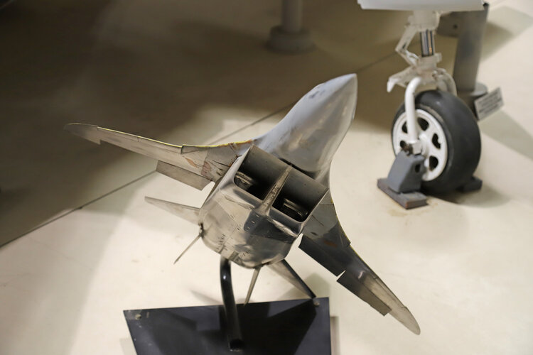
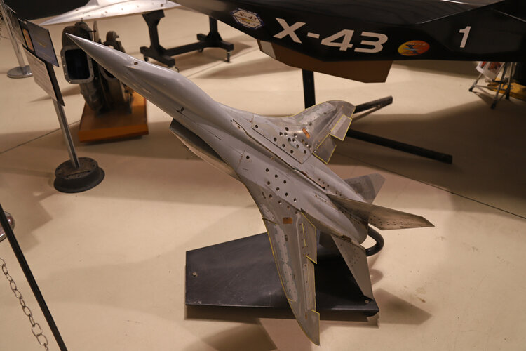
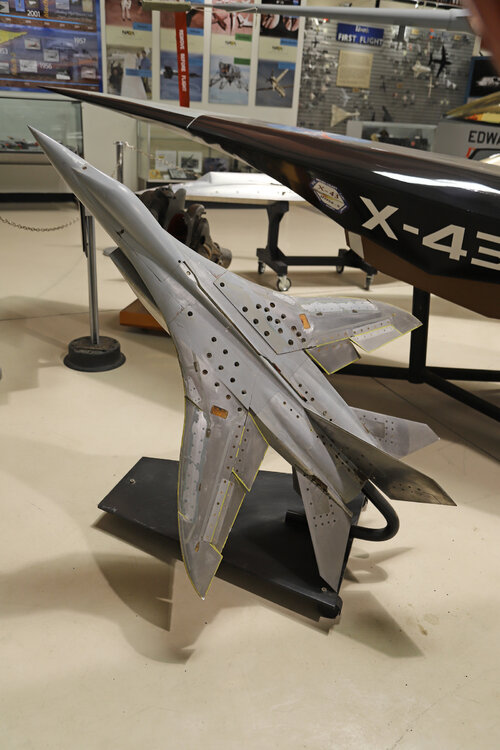
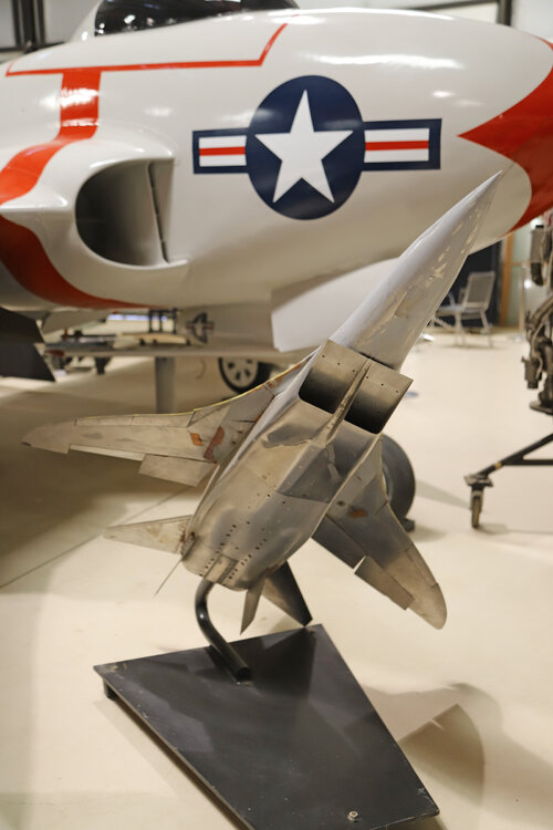
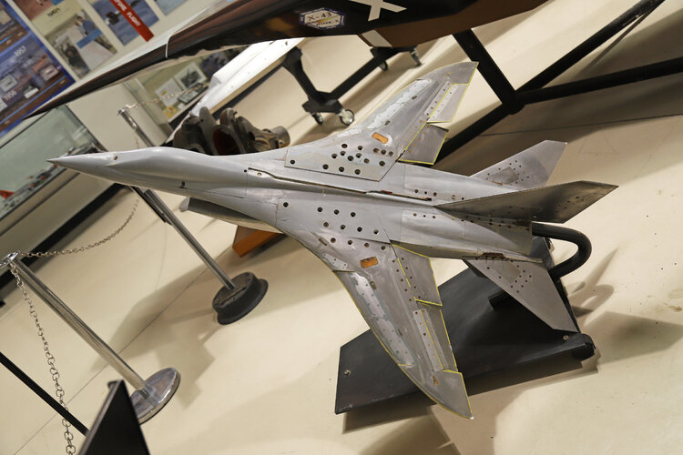
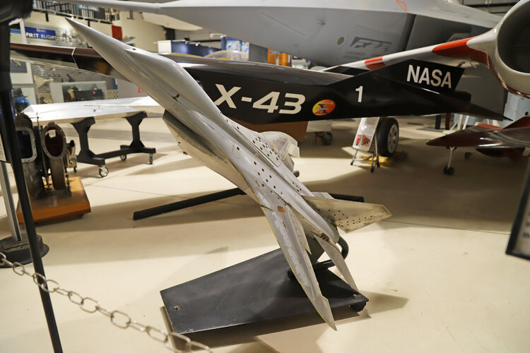
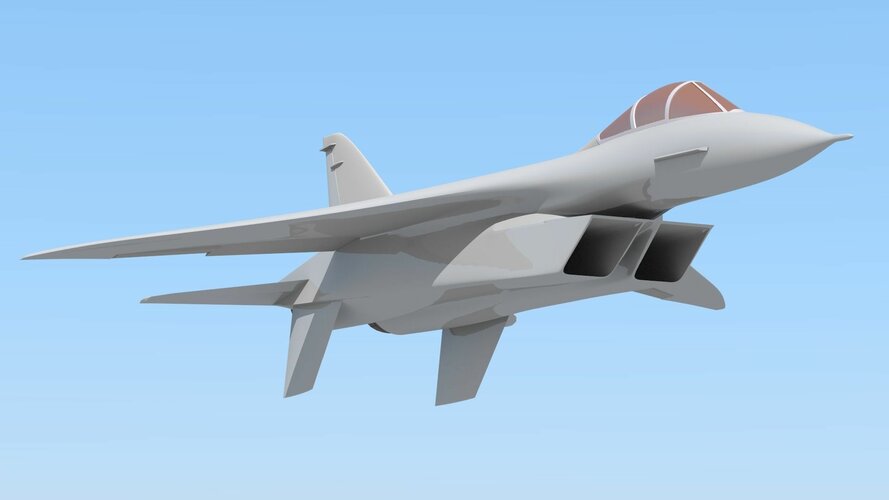
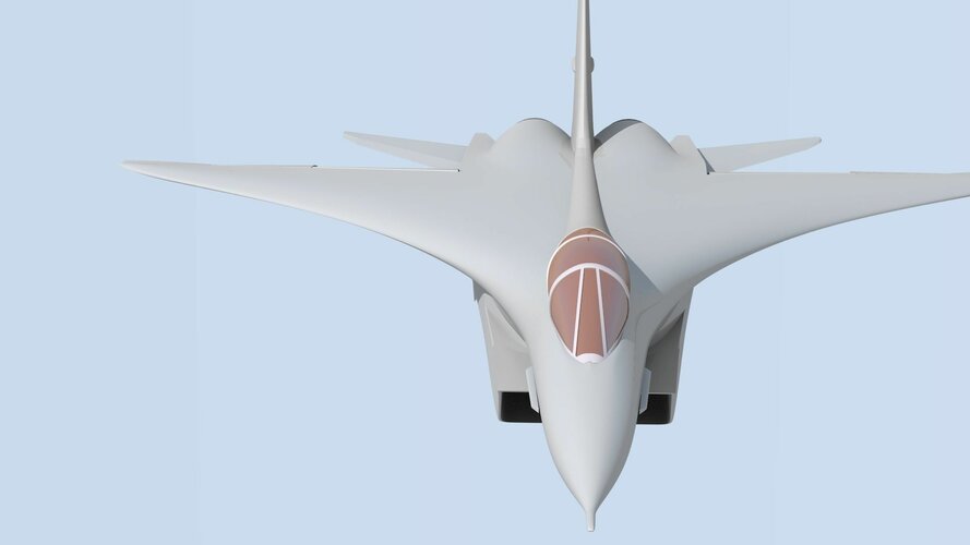
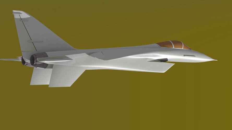
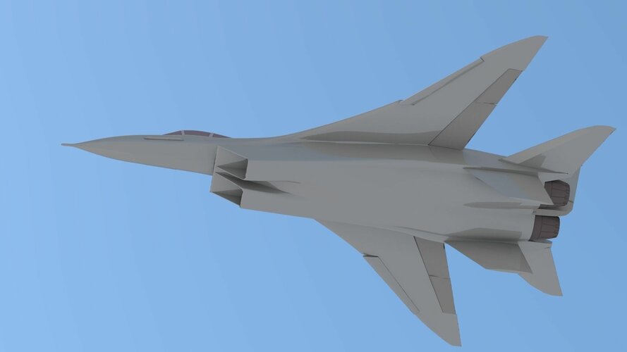
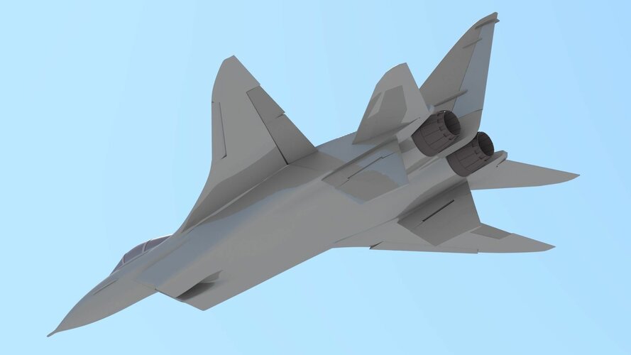
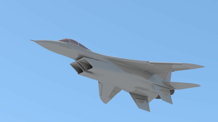
In the reserve, the designers had deeper studies that could be the basis of the future fighter of the new generation. Among the promising topics was the E-8M project with the S-23P weapon system and an increased wing area, which provided an increase in the bearing qualities and altitude of the machine. In another version, the E-8M was supposed to get side air intakes instead of the ventral, which, due to its proximity to the earth's surface, was too vulnerable to any debris that threatened to damage the engine. Another disadvantage of the ventral air intake with the anterior landing gear attached underneath was the excessive parking angle of the aircraft, which adversely affected take-off and landing - during take-off the aircraft with its nose up was accelerated more slowly due to significant aerodynamic drag, and during landing it was necessary to maintain a smaller angle to avoid grazing betonki tail section. With all the evidence, it was also taken into account that the side air intakes were established as the most common intake device scheme on almost all foreign aircraft of this class, having managed to prove the validity of such a decision in the layout of the aircraft and the practicality in its operation.

The abandonment of the simplest and most effective frontal air intake, which was a thing of the past with the previous generation of aviation equipment, was primarily a tribute to the requirements for the placement of airborne equipment - radar stations with their large antenna mirror, the dimension of which largely determined the radar's ability to detect objects. The growth in the diameter of the radar antenna systems became decisive for the designation of the midship of the aircraft fuselage, literally crowding out air intakes “to the outskirts” and dictating the layout solution of the entire machine. The scheme with lateral air intakes at that time looked the most suitable, in which the air path to the engine by was emitting a moderate length, allowing to reduce pressure losses. At the same time, such a scheme released the internal layout volumes used to store the fuel supply, all kinds of systems and equipment, which were a real problem to squeeze into the machine with a central inlet device with extended air channels.

The development of a promising fighter was still conducted under the general name MiG-23 (although not yet specified by the governing documents). The name was conditional, since in the usual way such a name was assigned to the aircraft only with its adoption, having been spelled out in the relevant Government Decree. But for all involved in the work, it was obvious that the future machine, by definition, would be prepared for exactly this name given in advance as the next to the “twenty-first”, regardless of the choice of a specific project and the appearance of the fighter. Separate options within the framework of the topic were factory codes and names as “Product” or the definition “Aircraft” with the next index adopted in OKB-155 practice. The S-23 weapon system and K-23 missiles designed for it were worn by the same digital index. The future MiG-23 was to become a counterweight to the American F-4. However, it would be wrong to say that the fighter created was to be primarily the answer to the Phantom, which is supposed to be the main enemy. The new generation fighter was supposed to have qualities that were not inferior to the entire arsenal of the potential enemy’s armament (and being prepared), the capabilities of which were also taken into account and stipulated when setting the task. One of the reports of a somewhat later time included “tactical fighters of the F-105D,” Phantom”, “Mirage” IIIC, tactical bombers of the B-58 type, cruise missiles of the Mace type and Hound Dog, military transport aircraft and helicopters". Meanwhile[PM2] , the requirements for the future machine were not only flight characteristics and the composition of equipment and weapons.

The issues of the basing of military aviation became urgent in the 60s. The development of supersonic speeds and the growth of other characteristics of new aircraft, which added in size and weight, were achieved by an equally significant increase in take-off and landing speeds. Landing speeds of combat aircraft reached a level of under 400 km/h, being at the limit acceptable to the pilot. The pursuit of flight speed, which for a long time dominated the minds of the military and the creators of aviation technology, turned into a growing accident rate on already difficult take-off and landing modes. The number of accidents and catastrophes during the development of new generation technology at the end of the 50s in our aviation reached 260 and more aircraft annually, the picture was not better observed abroad. According to the increased take-off and landing speeds, the required runway lengths increased. For the new aircraft that gained weight, field airfields and improvised platforms from which the post-war aviation worked were no longer suitable . The MiG-21PF during take-off with a pair of R-3S missiles and an outboard tank, the separation speed was 310-320 km/h, and the take-off distance reached 1500-1600 m. Landing speed was 275-300 km/h with a landing distance of 2300-2500 m, while the light "twenty-first" was considered to have good take-off and landing qualities, allowing its operation from airfields of the 2nd class (with a runway length of at least 2000 m). The problem was common to the whole new generation of combat aircraft, and the “probable enemy” pilots faced the same difficulties : neither the twenty-ton Phantom, nor the Thunderchief, nor even the relatively light Starfighter were adapted to work from unpaved airfields (and even physically incapable of this, having a pressure in the tyres of the undercarriage of 12-17 atm). As a result, with the development of jet technology, aviation turned out to be tied to stationary aerodromes with multi-kilometre concrete runways. Meanwhile, it was completely obvious that in the event of the outbreak of hostilities, the enemy would first try to disable the airfield network, and large airfields would inevitably be hit (as was demonstrated by the experience of post-war military conflicts). The use of nuclear weapons made the fate of large airbases a foregone conclusion, and the survival of aircraft located on them was primarily determined by the possibility of dispersal using alternate aerodromes and all kinds of suitable sites. The issue was all the more urgent because it determined not only the preservation of their aircraft from defeat at the very beginning of the conflict, but also the very possibility of its use in hostilities - it is clear that no one would be able to take off from broken airfields. It was necessary to take measures to ensure the possibility of combat aircraft from strips of limited size and dirt pads, and all other more or less suitable places, the network of which would allow the aircraft to be hidden from the enemy and increase the combat stability of units and formations.
 
Last edited:

"North American Rockwell Flanker " - Un-be-lie-va-ble. Was it a coincidence or deliberate ?
The Soviets were well aware of the F-X concepts when they began work in the mid-70's. Had the NAA plane flew it would likely have run into the same issues Sukhoi did however.

What many doen't seem to get is that a major part of the design phase of any engineering project is a literature study to see what and why others have done what they did and if it is applicable to your project. If you like what you see it might well get incorporated into your design in some shape or form. Novel ideas don't always mean great engineering...

Sukhoi clearly found inspiration but they drew plenty from other internal projects too with 1000's of windtunnel tests conducted and still they had to do a major redesign when the T-10 first flew.
 
The Soviets were well aware of the F-X concepts when they began work in the mid-70's. Had the NAA plane flew it would likely have run into the same issues Sukhoi did however.
Su-27 design was started in late 1969. By 1971 work was well underway. The primary inspiration was Sukhoi's T-4MS (blended wing/body) and reports on Concorde's ogival wing. They were aware of NAA's design and regarded it as better than McDonnell-Douglas's so were happy it lost.
 
Last edited:
The Soviets were well aware of the F-X concepts when they began work in the mid-70's. Had the NAA plane flew it would likely have run into the same issues Sukhoi did however.
Su-27 design was started in late 1969. By 1971 work was well underway. The primary inspiration was Sukhoi's T-4MS (blended wing/body) and reports on Concorde's ogival wing. They were aware of NAA's design and regarded it as better than McDonnell-Douglas's so were happy it lost.
Thanks overscan. I had my dates shifted between concept studies and actual deep design work starting.
The T-10/6 concept looks very, very similar to the NAA-355!
 
macnicol76
As a young aerodynamics engineer fresh out of graduate school, I worked for NAA and assisted the experienced NAA design engineers in evaluating the NA 335 design efforts. We were told by the Air Force brass that the NAA design was the best and that we had won the RFP competition. Therefore it was a huge shock when the announcement was made in late December 1969 that MD had won. We later learned it was a decision driven by politics. NAA’s NA 335 design was very advanced for 1969 being a psuedo-stealthy blended wing-body concept that resembled the future Lockheed F-22 and F-35 designs!

Comment left on Hushkit article which plundered the images from this topic.

Then there's THIS :-

As an interesting tidbit in Dan Raymer’s autobiography (Living in the Future) he mentions that the FX jettisonable magazine was the inhouse reason given as to why North American Rockwell lost the project. The ‘old timers’ at the company told Raymer that they had included the jettisonable magazine with all its extra weight and complexity in their FX tendered design (NA-335) as required by the specification. But rivals McDonnell had got wind that USAF was unhappy with the 25mm and in their tender left out all the weight of the jettisonable magazine and just provided a design with the conventional M61 20mm gun and ammo drum. So their F-15 was lighter and cheaper than the rivals who actually meet the specification as originally set by the customer.


cheers,
Robin.
 
Last edited by a moderator:
rockwellearlyfx-png.549043

Wind tunnel model used by North American Rockwell Corp, to help develop blended wing-body concept for Navy and Air Force fighter competitions is shown in three views. Slight negative dihedral applied to wing and horizontal tail is evident (top). Note extensive fairing of wing to fuselage to minimize wave drag and increase lifting surface. Blending of wing is continued forward to canopy station (middle). Light and dark patchy areas visible on upper aft fuselage are due to putty, added to solve flow separation problem, having fallen off during handling. Leading edge curvature is apparent in view at bottom.

Blended Wing-Body Tested for F- 15 Concept used by North American Rockwell in its fighter design proposal to provide transonic speed regime maneuverability
By C. M. Plattner
Los Angeles

Blended wing—body concept featuring a highly-curved leading edge and a careful fairing of wing to fuselage has been incorporated in the North American Rockwell F-15 air superiority fighter design proposal. The concept. refined in more than 8.000 hr. of wind tunnel work, is aimed at providing a fixed-wing planform optimized for good maneuverability in the transonic speed regime.

North American Rockwell’s Los Angeles Div. first advanced the concept in Navy's F-14 fighter design competition in the fall of 1968. Following additional refinement and orientation to USAF requirements, the blended wing-body concept also was incorporated in the F-15 proposal (AW&ST Nov. 24. p.32). North American Rockwell is competing with McDonnell Douglas Corp. and Fairchild Hiller Corp. for the contract to build the Air Force F-15 air superiority fighter. A winner may be selected early next year.

Wind Tunnel Work

Wind tunnel and analytical work on aerodynamics of the blended wing—body concept began in-house in 1966 although the Air Force was pushing for a variable-sweep wing configuration for its FX fighter. It was not until early 1968, however, that North American Rockwell began serious configuration refinement.

The idea grew from work by the advanced study group at Los Angeles Div. It was attractive because it appeared as a means of developing a fixed-wing planform to do the FX job without the complexity and weight penalties associated with variable-sweep wings. The key challenge was validation of the theory and building confidence so that Navy and Air Force customers would find the approach credible.

The blended wing-body work begun in 1966 was separate from the funded North American FX study that year of a variable-sweep wing FX design. Later. in 1968, a second round FX study competition was held. but North American Rockwell lost to McDonnell Douglas and General Dynamics Corp. the two contractors selected. However. North American conducted an unfunded study for the Air Force using the same ground rules but incorporating the blended wing—body work into a fixed—wing configuration.

The company last year also participated in the Navy F-14 competition, submitting the only fixed-wing design. This competition ultimately was won by Grumman. The North American Rockwell F-14 participation was a serious attempt to win. company officials said, but the blended wing-body concept was not as fully verified as would have been necessary for a maverick proposal to win. even if other factors had been equal. the officials believed.

The blended wing—body planform defies simple description. North American Rockwell aerodynamicists said. although terminology such as a seimitar wing and ogee shape is sometimes used. The shape is remarkably similar to the transonic wing configuration which was invented by R. T. Whitcomb of the National Aeronautics and Space,Administration’s Langley Research Center (.twasr Feb. 17, p. 22).

North American won a contract as the sole bidder on a NASA Flight Research Center project to build a transonic wing for installation on an LTV F-8 for flight test. Work is under way on this project now.

Shape Similarity

The reason for the similarity in shape is that the same suction theory was utilized to shape the leading edge. a North American Rockwell engineer said. The inboard portion is highly swept as it blends into the fuselage well forward. At about midspan. a point of inflection occurs and sweep angle is reduced. Near the tip. the leading edge begins to curve. increasing sharply in sweep angle to align with the local air stream. One of the considerations in translating a planform into hardware is the requirement for leading-edge flaps or slats. Ideally, a straight leading edge is desirable. but in the blended wingbody case. the need for leading-edge devices is minimized because of the ability to fly at high angles of attack.

Trailing edge can be a straight line to simplify flap and aileron design because the blended wing»body concept is relatively insensitive to trailing-edge shape, an engineer said. Studies have indicated that moderate sweep angles are desirable at mid-span, and every effort is made to maintain attached airflow over the entire wing rather than have vortexes form. Because maximum speed is not a crucial design criteria. as was the case with the XB-70, for example, a moderate rather than a low aspect ratio is employed with blended wing-body fighter designs. Maximum speed of the F—15 air superiority fighter—in the Mach 2.5 region—is in part related to a decision to utilize an aluminum airframe.

Probably the key design criteria in turning the blended wing-body idea into a workable fighter design has been the emphasis on good maneuverability in the Mach 0.6-1.4 speed regime with a minimum of buffet. This. combined with a low wing-loading and high thrust-to-weight ratio provides the maneuverability needed in a superior dogfight aircraft, the company believes.

The shape of the leading edge has been set by finding the best solution to the two separate requirements of the subsonic and the supersonic flight regimes. For supersonic flight. the curvature is dictated largely by Whitcomb’s area-rule theory for the best cross—sectional distribution along the longitudinal axis to minimize wave drag. Subsonic leading-edge shaping is based on the principle of maintaining a uniform suction distribution spanwise to minimize drag due to lift. The goal is to obtain high buffet free lift coefficients for maximum angle of attack before onset of flow separation. The curvature applied inboard and outboard directly influences the suction distribution.

Shock Formation

Tip curvature also is important in the transonic region. according to S. F. Kwiatkowski of North American Rockwell. because the onset of shock formation at wing tips is delayed. thereby reducing drag due to lift and improving buffet characteristics. In contrast to straight swept wings. the scimitar leading edge becomes supersonic more gradually as speed increases. The second major geometry refinement. blending the wing into the body, serves the basic purpose of raising the proportion of lift supplied by the fuselage. In design. this is done by continuing the wing airfoil section to the fuselage centerline. then maintaining this curvature as much as possible during the subsequent refinement process of working canopy. inlets. weapons and the like into the configuration. The benefit of blending the wing to the body is twofold. Kwiatkowski said. It moves the wing center of pressure inboard because of the added lift generated by the fairing. This. in turn. produces slightly lower wing bending moments and is beneficial from the structural standpoint.

Chief Goal

Reduction of wave drag is the chief goal, however, of blending the forward wing into the fuselage. An additional benefit at supersonic speed is that the highly-swept inboard fairing produces more lift than at subsonic speed and thus reduces the rearward shift of aerodynamic center to help lower the trim drag. Many of the fundamentals in the blended wing-body concept are founded on work done by NASA and, to some degree, that by the British. A North American Rockwell engineer noted that leading-edge shaping was done as long ago as the early 1950s with the Vickers-Armstrongs, Ltd., Supermarine Swift. In the wind tunnel test work on the blended wing-body configuration, the principles entailed have held up well, engineers said.

Photograph (p. 89) shows the last unclassified wind tunnel configuration prior to detailed refinement of the shape to military requirements. Some details, such as inlet and empennage shape, are believed to have changed, but the basic aerodynamic shape of the wing and fuselage remain the same. Camber and twist also are added in the final honing of the design and are not included in the photograph. North American Rockwell Los Angeles Div. refuses to discuss any specifics relative to its F-15 fighter design, but the 5.5-ft.-long wind tunnel model has been displayed at numerous public symposiums. It is believed to be a reasonably close likeness of the proposed F-15 in terms of wing and fuselage shape.

Basic Configuration
The same basic configuration was proposed to the Navy last fall, except that engines were moved inboard and a long common duct leading to a lower inlet under the nose was installed. The 5.5-ft. tunnel model is a force and moment model used for high-speed testing to obtain stability derivatives and performance parameters. It has aileron, flap and elevator segments, although they are not movable. Inlet design of the F-15 is believed to have changed in the direction of the F-14 design (AW&ST Dec. 16, 1968, p. 14) for the best efficiency and smoothest airflow to the engine.

AWST 8 December 1969
 
Last edited:
Such a shame they didn't design a convention 25mm cartridge and a simplified version of that cannon for if (or rather when) the caseless ammunition didn't work out.

Looking over that .pdf on the F-15's early development I'm surprised the Fairchild Hiller design rated higher on technical and operational factors than the NAA/Rockwell design. There is definitely some conflicting information out there from sources which suggest the USAF was leaning towards the NAA design.
 
Here are the three images from post #31 stitched together and cleaned up a bit. Note the name of the configurator/draftsman shown in the title block.
NAA F-15 proposal gen arrange.jpg
Just as an aside: I was told that, despite the violation of orthographic-projection rules used in the ' States, when possible, the top view of the airplane should point up (to avoid the lawn dart impression). ;)
 
Here are the three images from post #31 stitched together and cleaned up a bit. Note the name of the configurator/draftsman shown in the title block.
View attachment 709853
Just as an aside: I was told that, despite the violation of orthographic-projection rules used in the ' States, when possible, the top view of the airplane should point up (to avoid the lawn dart impression). ;)
That will help so much for making a model of the beast, thank you!
 
Back
Top Bottom