NASA Aircraft Projects

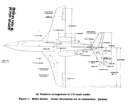
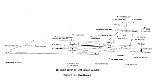
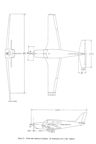
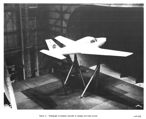
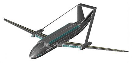
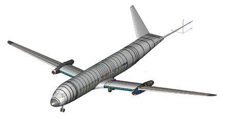
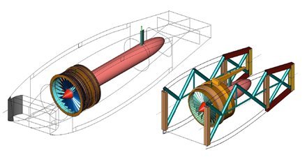
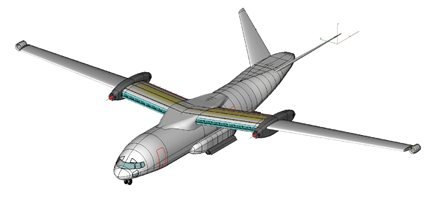
A 1/9 scale model of an existing executive type jet transport refitted with a supercritical wing was tested on in the 8 foot transonic pressure tunnel. The supercritical wing had the same sweep as the original airplane wing but had maximum thickness chord ratios 33 percent larger at the mean geometric chord and almost 50 percent larger at the wing-fuselage juncture. Wing pressure distributions and fuselage pressure distributions in the vicinity of the left nacelle were measured at Mach numbers from 0.25 to 0.90 at angles of attack that generally varied from -2 deg to 10 deg. Results are presented in tabular form without analysis.

http://ntrs.nasa.gov/archive/nasa/casi.ntrs.nasa.gov/19830002799_1983002799.pdf
 

Attachments

  • ExecutiveJetTop.png
    ExecutiveJetTop.png
    121.5 KB · Views: 297
  • ExecutiveJetSide.png
    ExecutiveJetSide.png
    79.7 KB · Views: 294
SUMMARY

The performance, stability, and control characteristics of a series of parachutes with extendable flaps are presented for a range of free-stream velocities from 20 to 60 feet per second. The tests included the variation of both flap length and flap width. The maximum lift-drag ratio which could be obtained depended upon flap configuration, flap extension, and suspension line length. Aerodynamic data obtained during the tests indicate that the parachutes were statically stable at all values of lift-drag ratio up through the maximum value. Visual observations indicated an increase in dynamic stability as lift-drag ratio increased.

INTRODUCTION

Conventional parachutes have been used for the recovery of space vehicles, but they provided no control of the glide path and, consequently, no choice of landing site. One means of providing glide-path control is through use of an extendable flap in one side of the canopy.

http://ntrs.nasa.gov/archive/nasa/casi.ntrs.nasa.gov/19620004429_1962004429.pdf
 

Attachments

  • Parachute01.png
    Parachute01.png
    132.5 KB · Views: 67
  • Parachute02.jpg
    Parachute02.jpg
    594.8 KB · Views: 66
  • Parachute03.jpg
    Parachute03.jpg
    591 KB · Views: 58
  • Parachute04.jpg
    Parachute04.jpg
    548 KB · Views: 63
The M1-L lifting body concept employs a high volumetric efficiency forebody and an inflatable afterbody that is deployed to provide lift-to-drag ratios sufficient for horizontal landings. The purpose of the investigation described here was to determine the low-speed aerodynamic characteristics of a large-scale model with an inflatable afterbody.

In addition, a model with a rigid afterbody was tested as a datum for aeroelastic characteristics. Deployment of the inflatable afterbody increased the maximum lift-to-drag ratio (L/D) from less than 1 t o slightly more than 2. This value was about 15 to 20 percent less than that for the model with the rigid afterbody.

Because a maximum L/D of about 2-1/2 is the minimum value required to accomplish a horizontal landing, this 20-percent reduction appeared to be the most significant effect of flexibility. Studies indicated that deployment of the inflatable afterbody is mechanically feasible.

http://ntrs.nasa.gov/archive/nasa/casi.ntrs.nasa.gov/19690029390_1969029390.pdf
 

Attachments

  • MIA04.jpg
    MIA04.jpg
    218.4 KB · Views: 88
  • MIA03.jpg
    MIA03.jpg
    224.9 KB · Views: 82
  • MIA02.jpg
    MIA02.jpg
    430.6 KB · Views: 72
  • MIA01.jpg
    MIA01.jpg
    476.1 KB · Views: 89
Graham1973 said:
Embarrassed to ask this, but can anyone tell me how to convert the scale measurements into the actual figures... :-[

The information in the drawings is incomplete: they don't list what scale this model is. You need 2 points of data to calculate the third:
scale measurement / scale = full-size measurement
(where the scale is listed as a fraction, e.g. 1/72)
 
Graham1973 said:
Embarrassed to ask this, but can anyone tell me how to convert the scale measurements into the actual figures... :-[

Ahem: Investigation Of A 0.3 Scale Jet-Transport Model

Simply multiply the model dimensions (listed in feet) by 1/0.3 (i.e.3.3333) to get full-scale dimensions.
 
Orionblamblam said:
Graham1973 said:
Embarrassed to ask this, but can anyone tell me how to convert the scale measurements into the actual figures... :-[

Ahem: Investigation Of A 0.3 Scale Jet-Transport Model

Simply multiply the model dimensions (listed in feet) by 1/0.3 (i.e.3.3333) to get full-scale dimensions.

Thanks,

Now I know where I was going wrong..
 
hesham said:

Interesting that they found a closing design for N+2 type designs with non-superconducting generators/motors and performance similar to a 737. Specifically the 737 bit. Though this size may be the current lower bound for the technology.
 
XP67_Moonbat said:
Shades of ISINGLASS.

Doesn't surprize me, ISINGLASS was being worked on around that time, searching for "boost-glide" on the NTRS brings up a mix of designs including what looks like one of the early Dyna-Soar concepts.
 
Here is a two NASA projects of the year 2012;

1- Compound Helicopter

2- Large helicopter
 

Attachments

  • NASA Compound Helicopter.JPG
    NASA Compound Helicopter.JPG
    45.2 KB · Views: 612
  • NASA Large helicopter.JPG
    NASA Large helicopter.JPG
    39.9 KB · Views: 610
And here is the Quiet Green Transport Concept A from another report:
 

Attachments

  • Quiet Green Transport Concept A.gif
    Quiet Green Transport Concept A.gif
    101.1 KB · Views: 225
A very unusual design appearing incidentally in an unrelated report. Can someone identify it?

Source: http://ntrs.nasa.gov/archive/nasa/casi.ntrs.nasa.gov/19730022211_1973022211.pdf
 

Attachments

  • unidentified NASA design.gif
    unidentified NASA design.gif
    24.1 KB · Views: 236
  • source.jpg
    source.jpg
    208.5 KB · Views: 235
A strange VTOL Fighter concepts;


http://ntrs.nasa.gov/archive/nasa/casi.ntrs.nasa.gov/19830003817_1983003817.pdf
 

Attachments

  • 2.JPG
    2.JPG
    47.2 KB · Views: 217
  • 1.JPG
    1.JPG
    29 KB · Views: 194
From 1988: Survey of Army/NASA Rotorcraft Aeroelastic Stability Research

Theoretical and experimental developments in the aeroelastic and aeromechanical
stability of helicopters and tilt-rotor aircraft are addressed. Included are the
underlying nonlinear structural mechanics of slender rotating beams, necessary for
accurate modeling of elastic cantilever rotor blades, and the development of dynamic
inflow, an unsteady aerodynamic theory for low-frequency aeroelastic stability
applications. Analytical treatment of isolated rotor stability in hover and forward
flight, coupled rotor-fuselage stability in hover and forward flight, and
analysis of tilt-rotor dynamic stability are considered. Results of parametric
investigations of system behavior are presented. and correlations between theoretical
results and experimental data from small- and large-scale wind-tunnel and
flight testing are discussed.
 
Thought I'd pass this one on... It's called the "Ram-Booster" (and it's not a new idea, Dani Edar did a study for Boeing in the mid-80s for a jet-engine booster for space launch) and it uses a turbojet first stage using multiple fighter engines at full-military power to push a second stage ramjet to Mach-2. The ramjet runs from Mach-2 to around Mach-4 and @100,000ft where the third (rocket-powered) stage seperates and flys into orbit.

http://www.nasa.gov/offices/ipp/centers/dfrc/technology/DRC-010-039-Ram-Booster.html

Randy
 
Hi,


the NASA SSBJ project Model.
 

Attachments

  • SSBJ.JPG
    SSBJ.JPG
    34.7 KB · Views: 1,559
http://www.airspacemag.com/multimedia/Canaveral-Junior-199246661.html
 
NASA Fan-On-Flap STOL concept, with sixteen (16) trailing edge turbines, driven by four (4) jet engines on pods. This photo currently for sale on eBay, without the graffiti.
 

Attachments

  • 6007485.jpg
    6007485.jpg
    74.1 KB · Views: 1,102
  • 6007486.jpg
    6007486.jpg
    227.9 KB · Views: 1,050
hwb_oil_visualization_larc_2013.jpg

Credit: NASA Langley/Preston Martin

http://www.dvice.com/2013-10-1/image-day-lifting-body-flourescent-flow​

You're looking at a 5.8 percent scale model of a "futuristic hybrid wing body" undergoing subsonic wind tunnel testing at NASA's Langley research center. The model was sprayed with flourescent oil, resulting in patterns that illustrate patterns of air flow. If (when) they build a full-scale version of this thing, my vote is that they should keep this paint job.
 

Similar threads

Back
Top Bottom