- Joined
- 27 December 2005
- Messages
- 18,716
- Reaction score
- 33,062
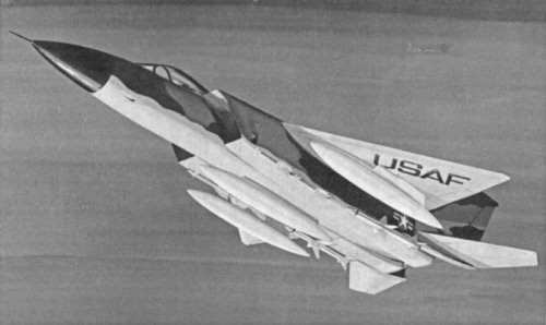
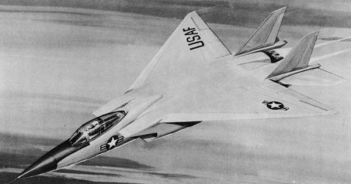
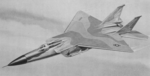
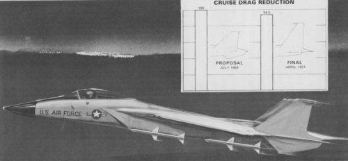
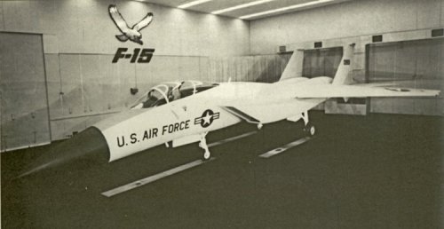
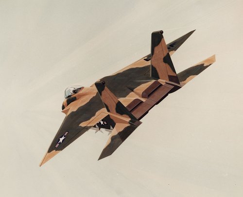
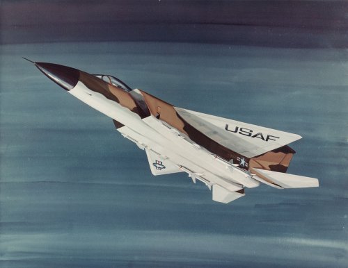
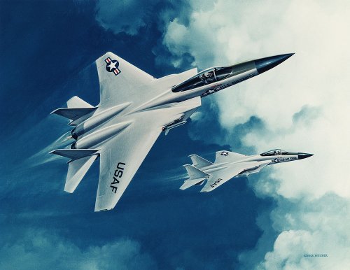
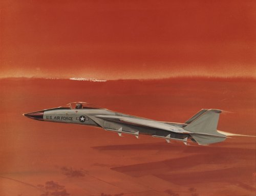
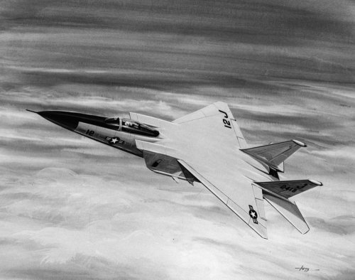
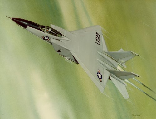
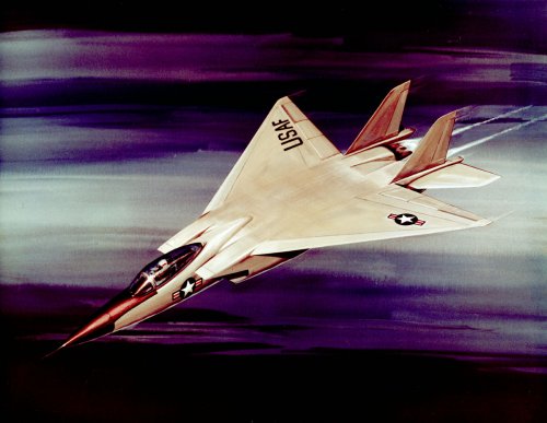
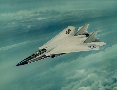
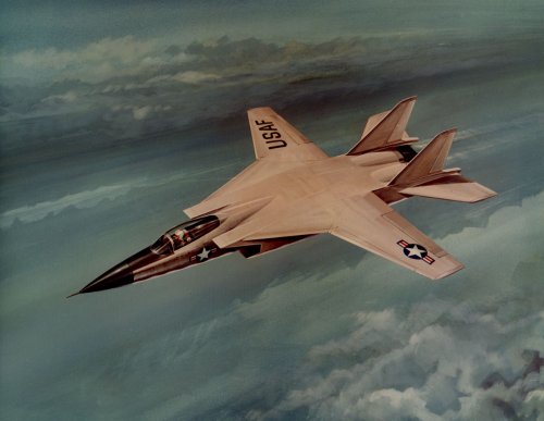
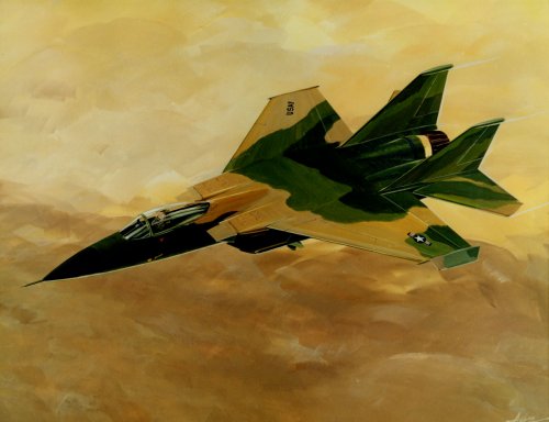
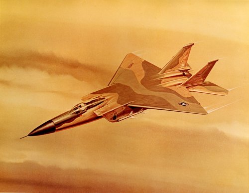
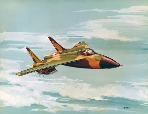
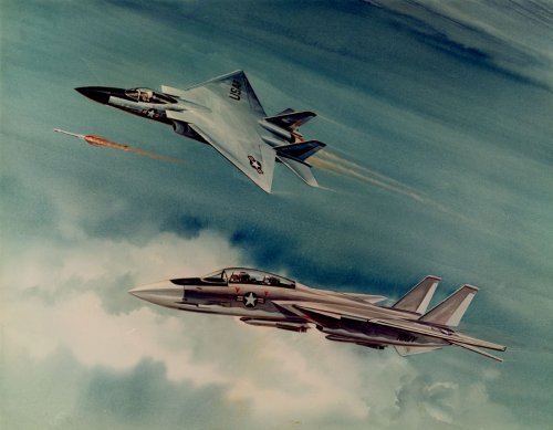
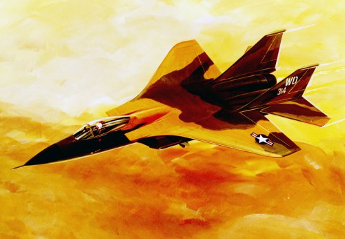
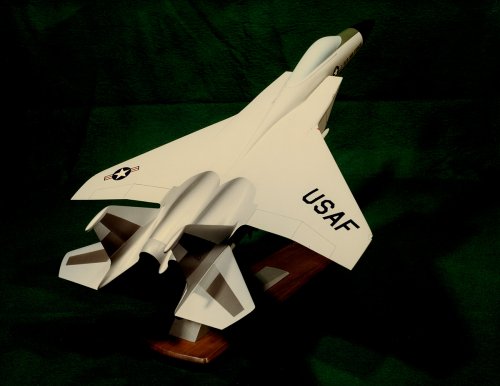
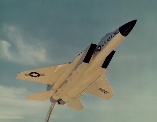
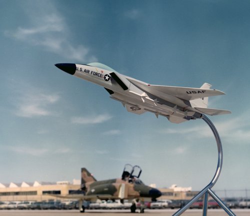
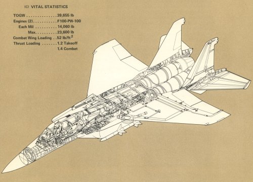
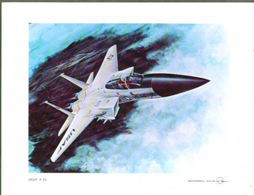
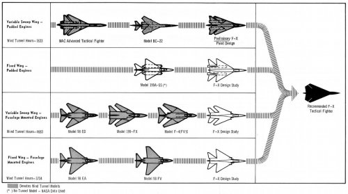
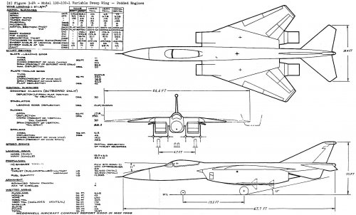
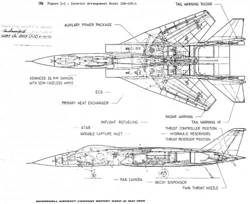
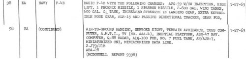
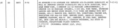
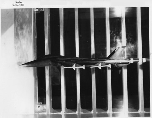
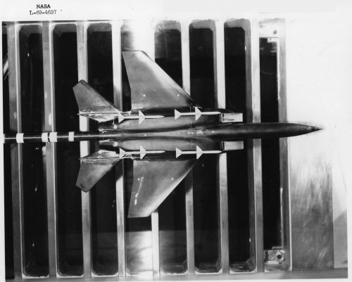
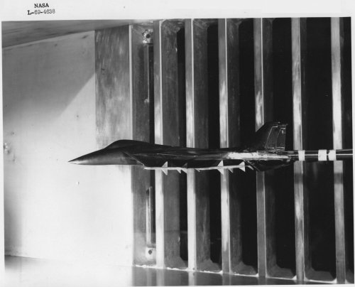
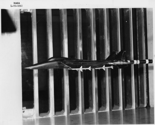
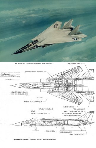
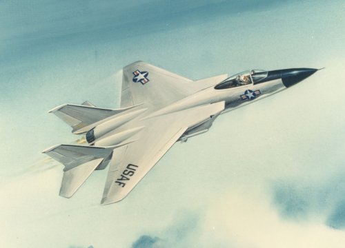
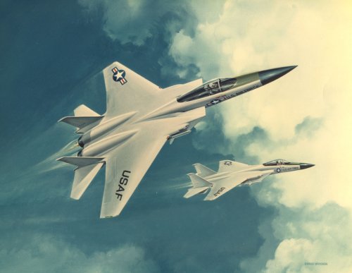
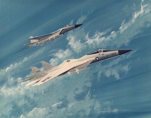
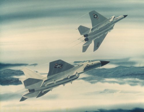
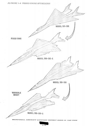
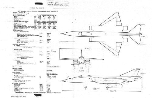
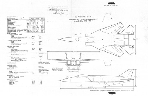
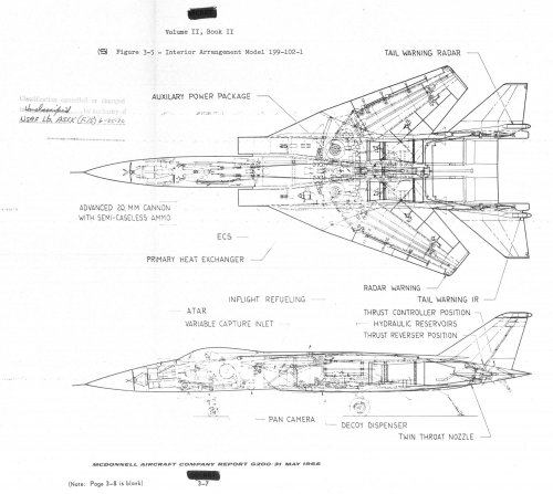
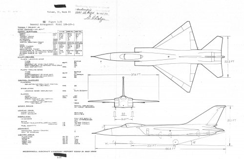
McDonnell-Douglas VG concepts
[Images removed - better scans below - Admin]
[Images removed - better scans below - Admin]

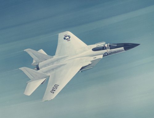
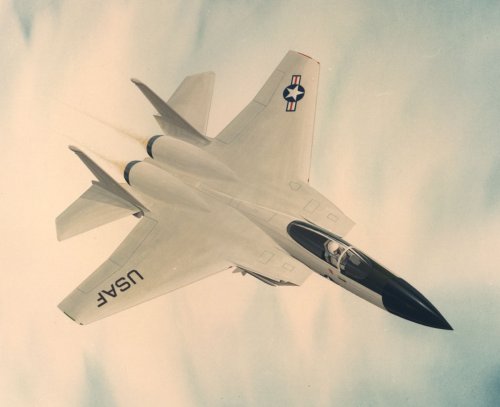
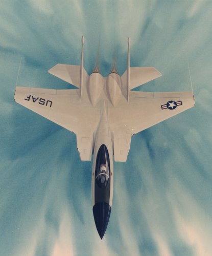
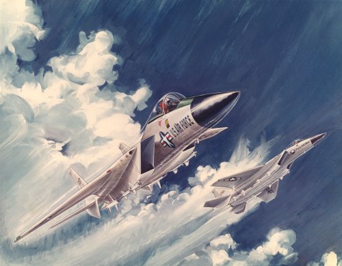
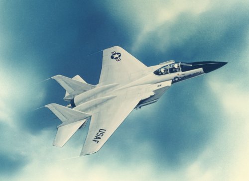
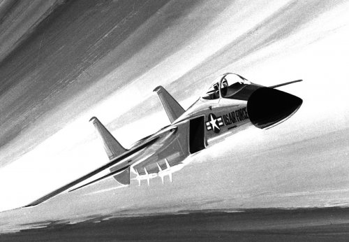
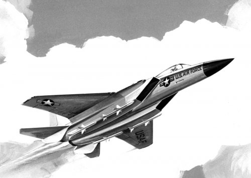
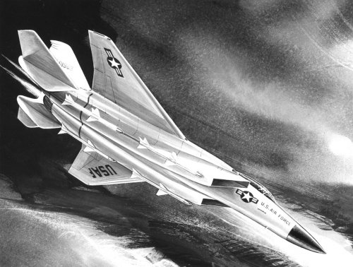
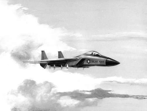
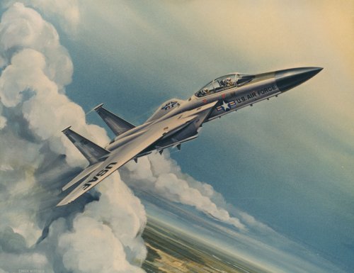
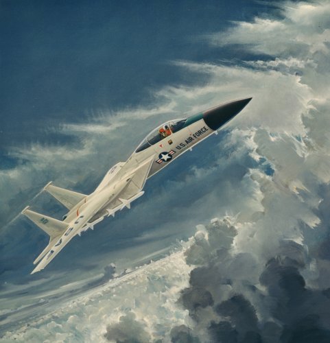
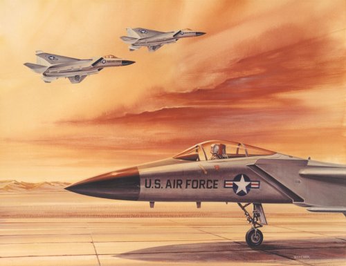
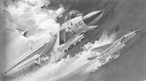
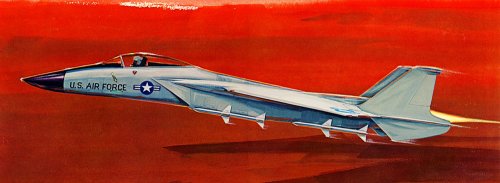
overscan said:Interestingly the drawings don't match the VG artwork we have to date:

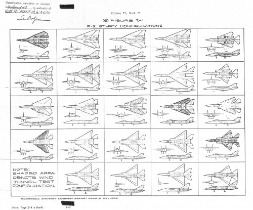
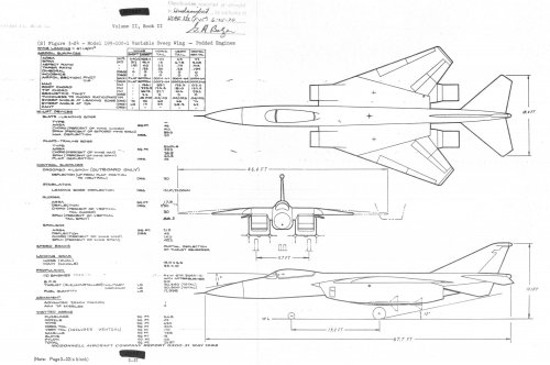
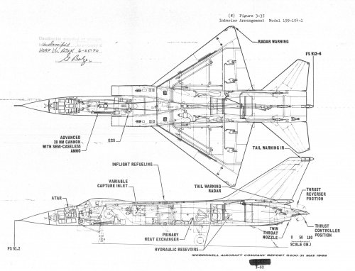
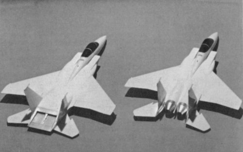
overscan said:Side by side - you may be correct. Intake looks different, fixed wing root sweep a bit wrong, but the rest is close. Perhaps the vertical tails are different and a fraction further forward in the artwork too.