- Joined
- 13 June 2007
- Messages
- 2,220
- Reaction score
- 3,541
Greetings All -
I probably should have started off with these first to maintain a time line with the design efforts.
Enjoy the Day! Mark
I probably should have started off with these first to maintain a time line with the design efforts.
Enjoy the Day! Mark
Attachments
-
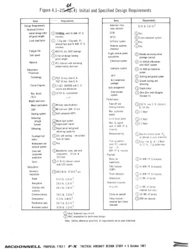 zMcAir FX - Initial & Specificed Design Requirements.jpg274.4 KB · Views: 522
 -
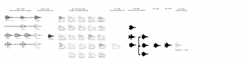
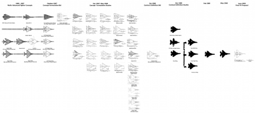
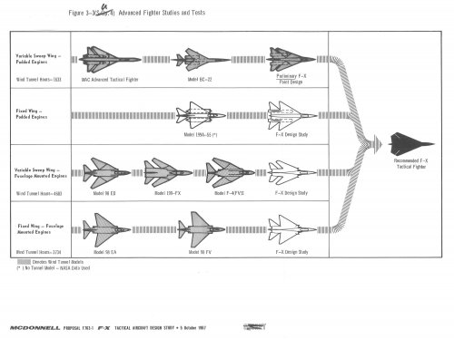 zMcAir FX Advanced Fighter Studies & Tests.jpg220.5 KB · Views: 738
 -
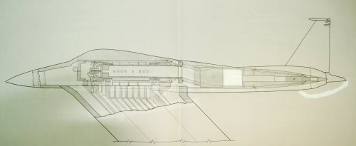
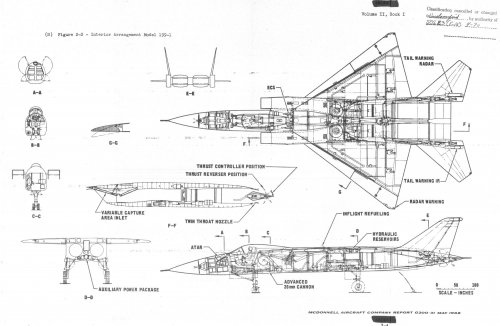
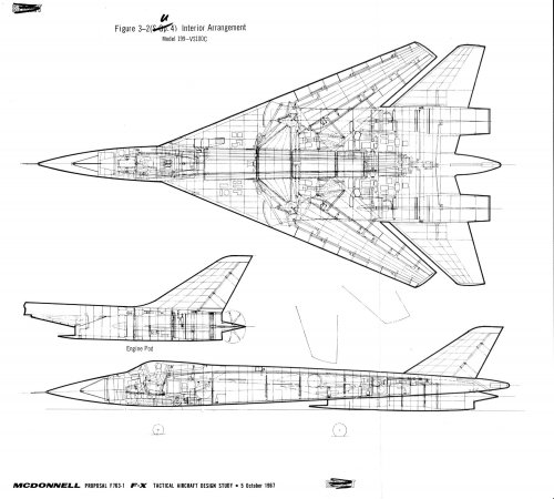 zMcAir Model 99-VS100C Interior Arrangement.jpg367.2 KB · Views: 747
 -
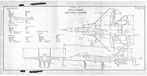
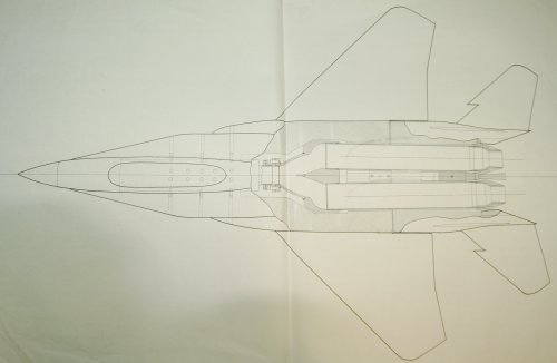
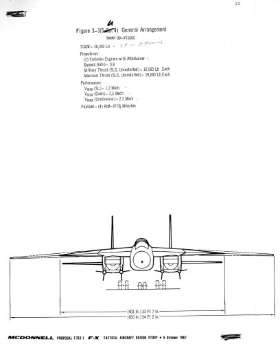
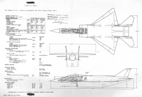
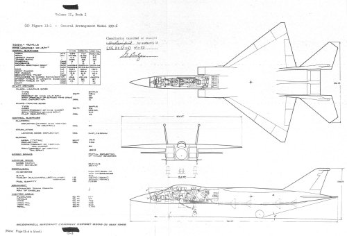
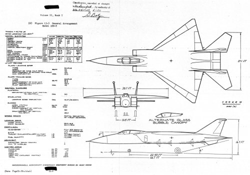
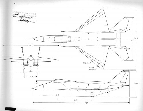
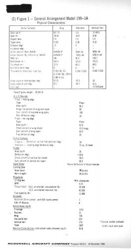
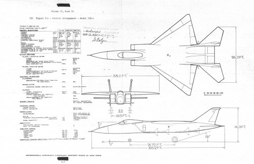
 zMcAir Model 99-VS100C General Arrangement-2.jpg213.6 KB · Views: 665
 -
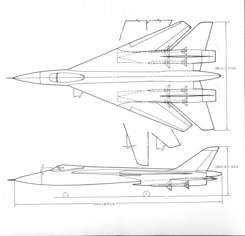
 zMcAir Model 99-VS100C General Arrangement-1.jpg149 KB · Views: 662
 -
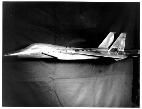
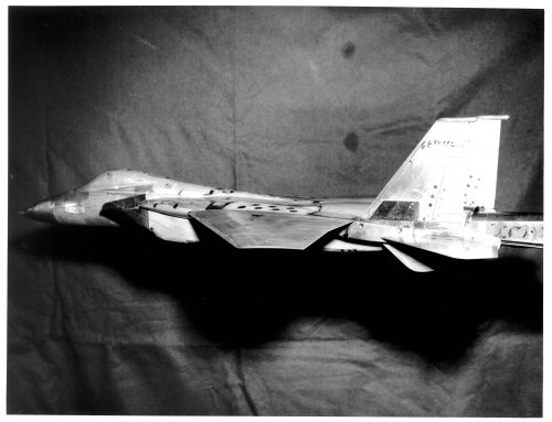
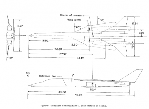
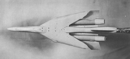
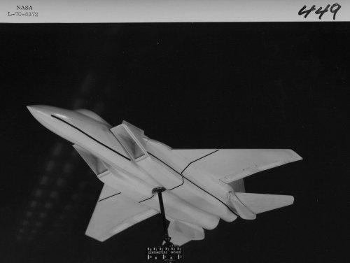
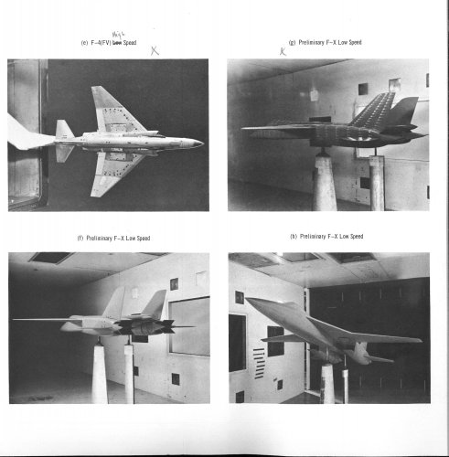 zMcAir FX Aerodynamic Wind Tunnel Models-b.jpg358.7 KB · Views: 621
 -
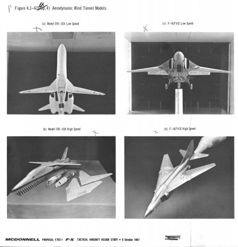 zMcAir FX Aerodynamic Wind Tunnel Models-a.jpg329.5 KB · Views: 599
 -
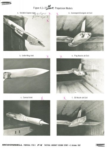 zMcAir FX Propulsion Models.jpg314.6 KB · Views: 594

![00011[3].jpg](/data/attachments/104/104146-a7c6dbe1c6e4c6f957cf90254c6470b1.jpg)