- Joined
- 1 May 2007
- Messages
- 2,595
- Reaction score
- 1,965
This aircraft has been mentioned in a couple of threads, here :-
http://www.secretprojects.co.uk/forum/index.php/topic,14200.msg143338.html#msg143338
http://www.secretprojects.co.uk/forum/index.php/topic,3808.msg29919.html#msg29919
but doesn't seem to have a topic of it's own.
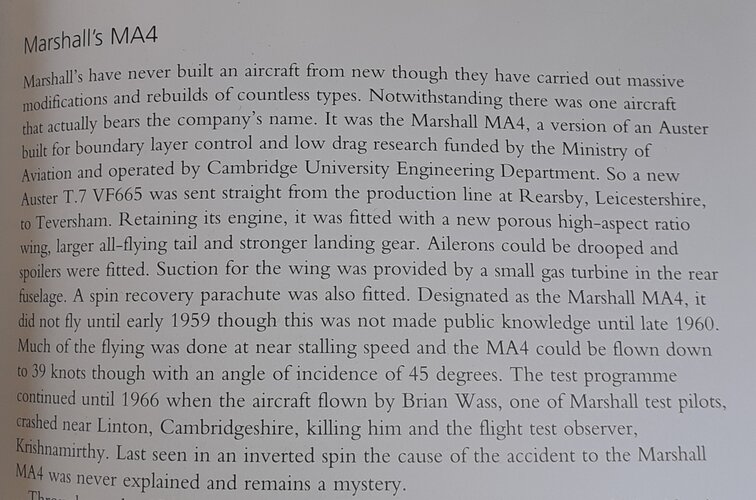
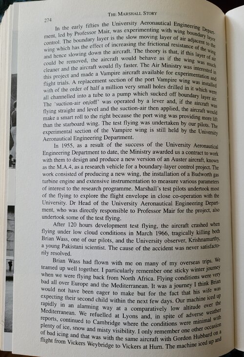
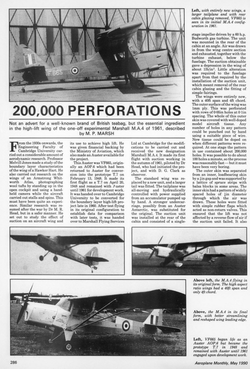
In the period after the war, several manufacturers and institutions, including Handley Page, and the University of Cambridge, were interested in the use of suction on aircraft wings, to remove the turbulent boundary layer, to reduce drag and increase lift.
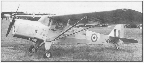
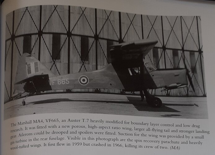
In 1960 the University of Cambridge obtained Ministry of Aviation funding to persue this project, by means of a flying testbed. An aircraft was also made available, this being Auster VF665, originally built as an AOP.6, before being converted as the prototype T.7. Upon being handed over to the University, it was test flown in it's original configuration to obtain baseline comparison data. It then went to Marshall Flying Services of Cambridge for conversion, receiving the new designation Marshall MA.4.
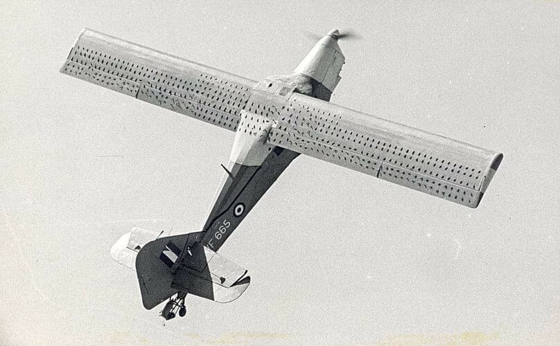
The wings and tail were replaced, and a stronger undercarriage was fitted. The new tail unit was larger, and the tailplane was all-moving and hydraulically powered. The power was supplied by an accumulator, pressurised via a hand pump. The wings were completely new, of 40' span and 4' chord. The outer skin was of 1mm plywood, perforated at 0.1" spacing with 0.05" diameter holes, in a grid pattern. This whole was then covered with doped model aeroplane tissue (!) This allowed any number, and any pattern, of holes to be produced, by means a piece of fine wire, and lots of patience! Apparently it was possible to punch 100 holes per minute, but with the patterns containing up to 200,000 holes, it would still have been a long job...
when a new pattern was required, new tissue was doped on the wing. This outer skin was carried on an inner, loadbearing skin, separated by a gap of 1/4" (6mm), and supported by spruce strips and balsa blocks. The inner skin had a series of 1/4" diameter holes, widely spaced, through which the air was drawn. These holes were fitted with rubber flaps, acting as non-return valves. These ensured there was no lift destroying reverse air flow should the suction unit fail, and also meant that this unit was not essential for flight.
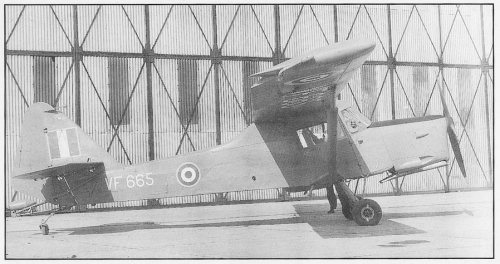
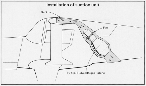
Large plain flaps and drooping ailerons were fitted to the wing, and these were also perforated, ducts connecting them to the wing interior. Air from the wing interior exhausted into the centre-section, and thence to the suction unit, which consisted of a single-stage impeller powered by a 60 hp Budworth gas turbine. This was mounted in the rear of the cabin at an oblique angle, the suction air, together with the turbine exhaust, discharging beneath the fuselage. Modifications made to the fuselage included removal of the rear cabin glazing, and the fitting of fairings. When running, the suction unit produced a pressure differential of around 1lb/sq.in, between the wing interior and the atmosphere.
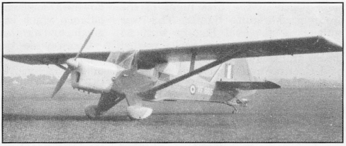
In this form, as flown, the MA.4 was underpowered. Therefore the aircraft was modified in order to reduce drag as far as possible. The fuselage was altered to give a smooth line from the wing trailing edge to the base of the fin, and the undercarriage was faired and spats fitted. Any drag producing 'lumps and bumps' were faired or sealed. Following these modifications the MA.4 showed a much improved speed and rate of climb. In this form the aircraft had a stalling speed of 57mph, reducing to 40mph with suction on. This could still be improved on, so the leading edge was reshaped. this reduced the stalling speed to 30mph at an angle of attack of 40 degrees.
On March 9th, 1966, during a research flight, the MA.4 crashed, and was wrecked, killing both the crew on board. No cause for the crash was released, but is thought that a trailing static tube, in the process of being hauled in, became entangled with the tail unit.
Images :-
1, Marshall MA.4 as first completed.
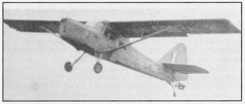
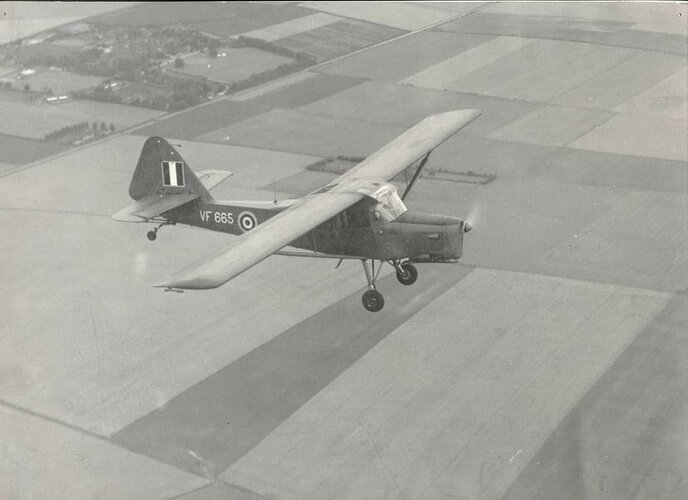
2, Marshall MA.4 first form in flight,
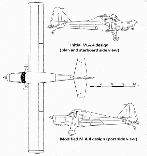
3, Marshall MA.4 following modification
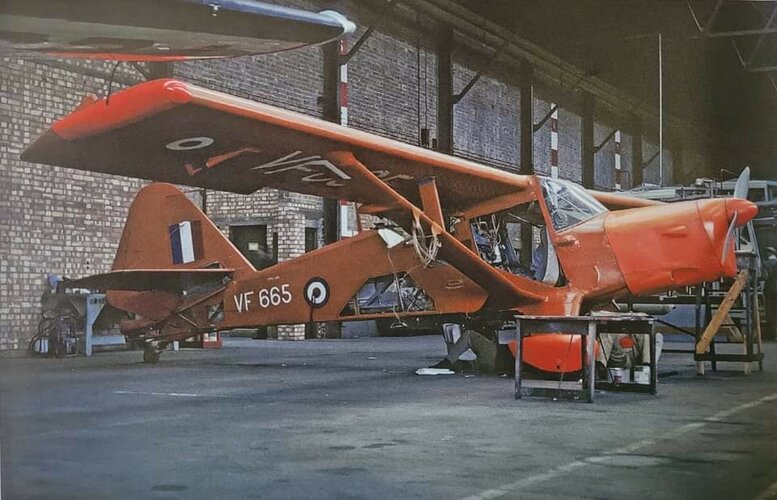
4, Marshall MA.4 before conversion, as Auster VF665
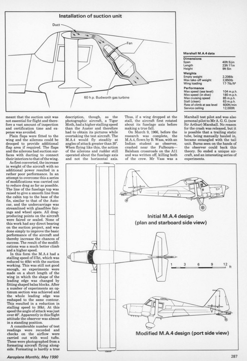
5, Installation of the suction unit in Marshall MA.4
6, Marshall MA.4 3-view.
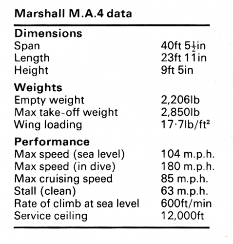
7. Marshall MA.4 data table.
from 'Aeroplane Monthly'. May 1990.
cheers,
Robin.
http://www.secretprojects.co.uk/forum/index.php/topic,14200.msg143338.html#msg143338
http://www.secretprojects.co.uk/forum/index.php/topic,3808.msg29919.html#msg29919
but doesn't seem to have a topic of it's own.
In the period after the war, several manufacturers and institutions, including Handley Page, and the University of Cambridge, were interested in the use of suction on aircraft wings, to remove the turbulent boundary layer, to reduce drag and increase lift.
In 1960 the University of Cambridge obtained Ministry of Aviation funding to persue this project, by means of a flying testbed. An aircraft was also made available, this being Auster VF665, originally built as an AOP.6, before being converted as the prototype T.7. Upon being handed over to the University, it was test flown in it's original configuration to obtain baseline comparison data. It then went to Marshall Flying Services of Cambridge for conversion, receiving the new designation Marshall MA.4.
The wings and tail were replaced, and a stronger undercarriage was fitted. The new tail unit was larger, and the tailplane was all-moving and hydraulically powered. The power was supplied by an accumulator, pressurised via a hand pump. The wings were completely new, of 40' span and 4' chord. The outer skin was of 1mm plywood, perforated at 0.1" spacing with 0.05" diameter holes, in a grid pattern. This whole was then covered with doped model aeroplane tissue (!) This allowed any number, and any pattern, of holes to be produced, by means a piece of fine wire, and lots of patience! Apparently it was possible to punch 100 holes per minute, but with the patterns containing up to 200,000 holes, it would still have been a long job...
when a new pattern was required, new tissue was doped on the wing. This outer skin was carried on an inner, loadbearing skin, separated by a gap of 1/4" (6mm), and supported by spruce strips and balsa blocks. The inner skin had a series of 1/4" diameter holes, widely spaced, through which the air was drawn. These holes were fitted with rubber flaps, acting as non-return valves. These ensured there was no lift destroying reverse air flow should the suction unit fail, and also meant that this unit was not essential for flight.
Large plain flaps and drooping ailerons were fitted to the wing, and these were also perforated, ducts connecting them to the wing interior. Air from the wing interior exhausted into the centre-section, and thence to the suction unit, which consisted of a single-stage impeller powered by a 60 hp Budworth gas turbine. This was mounted in the rear of the cabin at an oblique angle, the suction air, together with the turbine exhaust, discharging beneath the fuselage. Modifications made to the fuselage included removal of the rear cabin glazing, and the fitting of fairings. When running, the suction unit produced a pressure differential of around 1lb/sq.in, between the wing interior and the atmosphere.
In this form, as flown, the MA.4 was underpowered. Therefore the aircraft was modified in order to reduce drag as far as possible. The fuselage was altered to give a smooth line from the wing trailing edge to the base of the fin, and the undercarriage was faired and spats fitted. Any drag producing 'lumps and bumps' were faired or sealed. Following these modifications the MA.4 showed a much improved speed and rate of climb. In this form the aircraft had a stalling speed of 57mph, reducing to 40mph with suction on. This could still be improved on, so the leading edge was reshaped. this reduced the stalling speed to 30mph at an angle of attack of 40 degrees.
On March 9th, 1966, during a research flight, the MA.4 crashed, and was wrecked, killing both the crew on board. No cause for the crash was released, but is thought that a trailing static tube, in the process of being hauled in, became entangled with the tail unit.
Images :-
1, Marshall MA.4 as first completed.
2, Marshall MA.4 first form in flight,
3, Marshall MA.4 following modification
4, Marshall MA.4 before conversion, as Auster VF665
5, Installation of the suction unit in Marshall MA.4
6, Marshall MA.4 3-view.
7. Marshall MA.4 data table.
from 'Aeroplane Monthly'. May 1990.
cheers,
Robin.