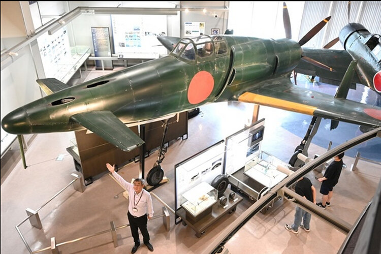
Awesome! Hopefully the real one gets put together, it should really be a higher priority imoHi Members. Apologies if a re-post (searched but not located) - the Tachiarai Peace Memorial Museum located in Asakura, Fukuoka, has built a 1:1 replica of this wonderful bird. Asahi Shimbun English article here.

You are using an out of date browser. It may not display this or other websites correctly.
You should upgrade or use an alternative browser.
You should upgrade or use an alternative browser.
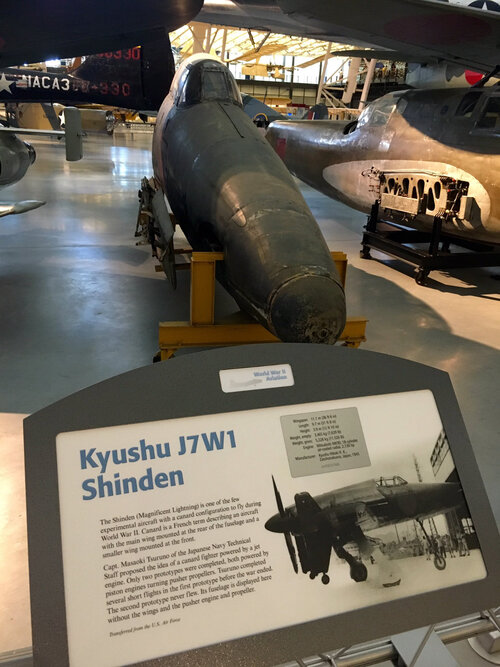
Kyushu J7W1 Shinden/J7W2 Shinden-kai
- Thread starter hesham
- Start date
- Joined
- 19 July 2016
- Messages
- 4,275
- Reaction score
- 3,459
There is a cheap card model, rescale it and use dapron and fly that. Simple structure and light enough, especially if made in card and paper that it is replaceable if pranged.
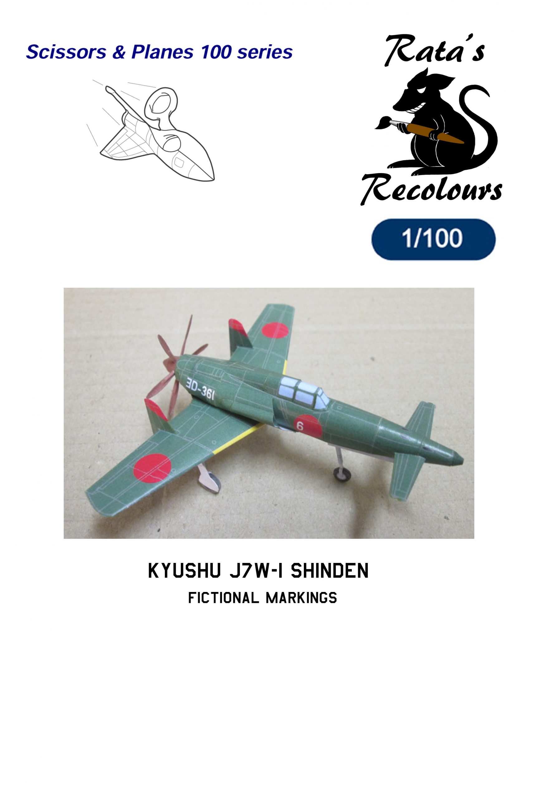
1/100 Kyushu J7W-1 Shinden - Fictional Markings - Paper Model - EcardModels
1/100 Kyushu J7W-1 Shinden - Fictional Markings - Paper Model
 ecardmodels.com
1/100 Kyushu J7W-1 Shinden - Fictional Markings - Paper Model - EcardModels
1/100 Kyushu J7W-1 Shinden - Fictional Markings - Paper Model
Scott Kenny
ACCESS: USAP
- Joined
- 15 May 2023
- Messages
- 11,628
- Reaction score
- 14,305
You want a prop with a prime number of blades. 1, 3, 5, 7, 11, ... This means that there is only one harmonic vibration frequency to worry about. 5 blades is about the optimum for ease of design in a controllable pitch prop.I did not know the production version was to have a 4 blade propeller. I really like the 6 bladed prop, very cool!the Ki-93 also had 6 blade props as did the prototype Ki-94-II. You have to wonder at what point is more propeller blades overkill though. The 5 blade prop was used in versions of the Spitfire so maybe 5 is the practical and useful limit. Maybe someone with an engineering background could shed some light on this...
I have seen an 11 blade prop on a modern turboprop (Beech King Air, I think), which does interesting things to the noise and prop efficiency due to the long and thin blades. But it's a tight fit to cram all the blade roots into the hub.
Scott Kenny
ACCESS: USAP
- Joined
- 15 May 2023
- Messages
- 11,628
- Reaction score
- 14,305
I don't think that anyone had figured out just how bad it was to have the fuselage boundary layer in your intake at this time, neither the P-59 nor P-80 had boundary layer fences in their inlets.Japanese technology was rather low level at the day. ;D
Scott Kenny
ACCESS: USAP
- Joined
- 15 May 2023
- Messages
- 11,628
- Reaction score
- 14,305
It's a very unusual shape, looks fast. It makes a great "what if" discussion.Wow!!!! Shinden is popular especially in western people.
Scott Kenny
ACCESS: USAP
- Joined
- 15 May 2023
- Messages
- 11,628
- Reaction score
- 14,305
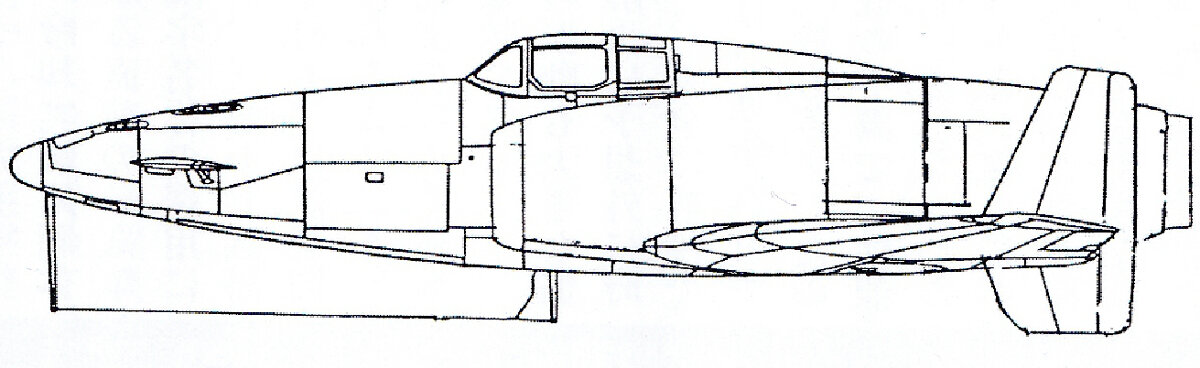
If designed correctly, an exhaust ejector tube can increase airflow through the overall structure, as well as providing some jet thrust. The Cessna 310 uses this concept to help cool the engines by increasing air velocity through the nacelles, for example.Hi! You can see engine exhaust nozzle shape for oil cooler ejector in this side view and model picture.
This picture's explanation is mistake. The equipment which called oil cooler is ejector for oil cooler. Engine oil can not be cooled by hot exhaust gas.
Or they define oil cooler as oil cooler +ejector?
does anyone has "試製震電 計画説明書" (Test Production Shinden - Project Instructions) of pdf version? If so I really need some help (original blueprints or manual books are also ok), I could also provide some project reports of other japanese planes in exchange
blackkite
Don't laugh, don't cry, don't even curse, but.....
- Joined
- 31 May 2007
- Messages
- 8,819
- Reaction score
- 7,716
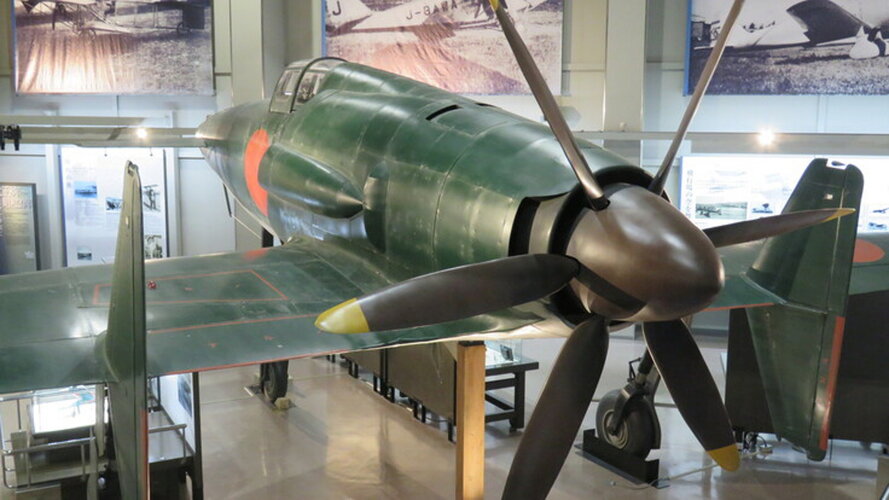
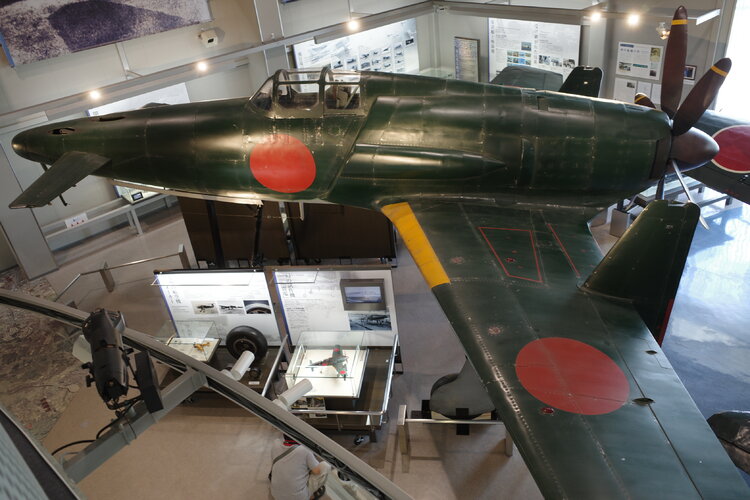
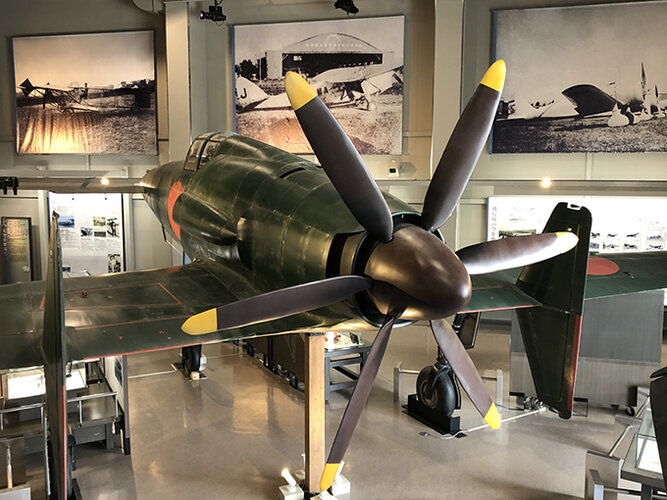
Hi! Shinden full scale model and restored Zero type32.
View: https://www.youtube.com/watch?v=HrKBrkDFF3Q
Attachments
Last edited:
blackkite
Don't laugh, don't cry, don't even curse, but.....
- Joined
- 31 May 2007
- Messages
- 8,819
- Reaction score
- 7,716
Hi another movie.
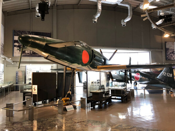
You can see detail of Shinden model , restored Zero type 32 and restored Type 97 fighter in Chikuzenmachi Tachiarai Peace Memorial Museum located near Fukuoka, Kushu.
View: https://www.youtube.com/watch?v=yZE2TxxC38c
You can see detail of Shinden model , restored Zero type 32 and restored Type 97 fighter in Chikuzenmachi Tachiarai Peace Memorial Museum located near Fukuoka, Kushu.
Last edited:
The K2
ACCESS: Secret
- Joined
- 29 June 2020
- Messages
- 303
- Reaction score
- 683
The Shinden plays a pivotal role in the new film ‘Godzilla Minus One.’Hi another movie.
You can see detail of Shinden model , restored Zero type 32 and restored Type 97 fighter in Chikuzenmachi Tachiarai Peace Memorial Museum located near Fukuoka, Kushu.
View: https://www.youtube.com/watch?v=yZE2TxxC38c
Scott Kenny
ACCESS: USAP
- Joined
- 15 May 2023
- Messages
- 11,628
- Reaction score
- 14,305
It's on my list for the next visit.Please come to Japan and watch this surprising model.
was this a fully flying replica, a ground runner, or a completely inoperative display only model?
blackkite
Don't laugh, don't cry, don't even curse, but.....
- Joined
- 31 May 2007
- Messages
- 8,819
- Reaction score
- 7,716
I will ask the detail of this model to the museum. Give me time.
Perhaps this model is not a fully flying replica, or not a ground runner.
I don't see such a Youtube movie still now.
Perhaps this model is not a fully flying replica, or not a ground runner.
I don't see such a Youtube movie still now.
- Joined
- 19 July 2016
- Messages
- 4,275
- Reaction score
- 3,459
I would really like to see flying replica's of some of these lost 'birds, the sky would be a better place with them there.
Not going to happen but I can dream. Pretty sure modern materials and aeronautical science couild cure the few problems with handling etc.
Not going to happen but I can dream. Pretty sure modern materials and aeronautical science couild cure the few problems with handling etc.
- Joined
- 11 March 2012
- Messages
- 3,249
- Reaction score
- 3,178
If you ask some of the test pilots who flew Shinden or Curtiss Ascender prototypes that they had … er … satisfied their curiosity.I would really like to see flying replica's of some of these lost 'birds, the sky would be a better place with them there.
Not going to happen but I can dream. Pretty sure modern materials and aeronautical science couild cure the few problems with handling etc.
Both of those early canards needed extensive re-design to fly like a normal airplane. For example, they needed centres-of-gravity farther forward and rudders much farther aft.
Hi Rob,
I once tried to create a Shinden model for X-Plane, staying as close to the historic information as I could, and the result was a plane that didn't fly very well. It would either show insufficient elevator autority, or end up stalling the main wing before the canard.
The reason might just be my own cluelessness regarding canard design, of course, combined with the greater sensitivity of canard design to subtle design details I might not have gotten right.
Regards,
Henning (HoHun)
If you ask some of the test pilots who flew Shinden or Curtiss Ascender prototypes that they had … er … satisfied their curiosity.
Both of those early canards needed extensive re-design to fly like a normal airplane. For example, they needed centres-of-gravity farther forward and rudders much farther aft.
I once tried to create a Shinden model for X-Plane, staying as close to the historic information as I could, and the result was a plane that didn't fly very well. It would either show insufficient elevator autority, or end up stalling the main wing before the canard.
The reason might just be my own cluelessness regarding canard design, of course, combined with the greater sensitivity of canard design to subtle design details I might not have gotten right.
Regards,
Henning (HoHun)
martinbayer
ACCESS: Top Secret
- Joined
- 6 January 2009
- Messages
- 3,397
- Reaction score
- 3,904
Imagine a world where canards of the *original* Wright Brothers design were considered "a normal airplane"...If you ask some of the test pilots who flew Shinden or Curtiss Ascender prototypes that they had … er … satisfied their curiosity.
Both of those early canards needed extensive re-design to fly like a normal airplane. For example, they needed centres-of-gravity farther forward and rudders much farther aft.
blackkite
Don't laugh, don't cry, don't even curse, but.....
- Joined
- 31 May 2007
- Messages
- 8,819
- Reaction score
- 7,716
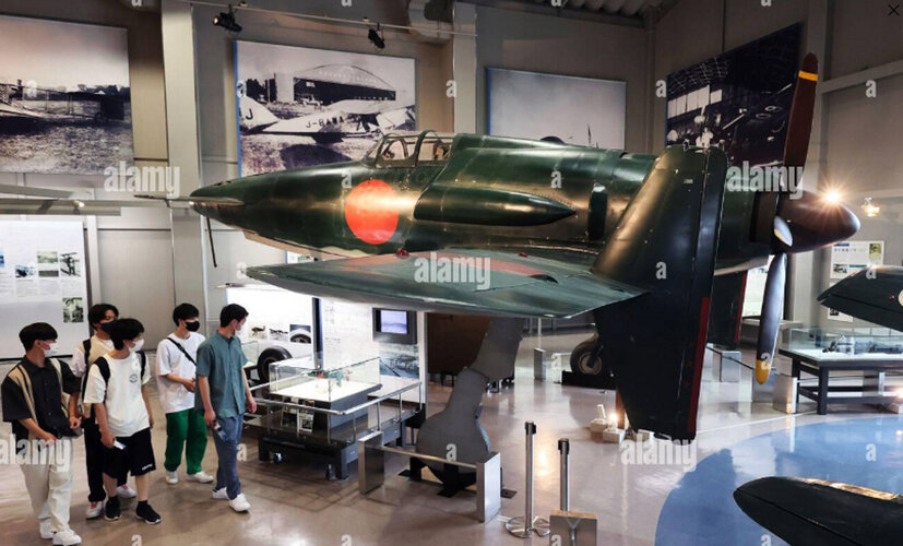
I received following information from Chikuzenmachi Tachiarai Peace Memorial Museum.
The Oosawa company made this exhibition model.
This model has no engine.
 www.oosawa.net
Today I watch ‘Godzilla -1.0 (Minus One).’
Shinden is very fascinating.
View: https://www.youtube.com/watch?v=PgkBPejm67I
The Oosawa company made this exhibition model.
This model has no engine.
会社情報|映画撮影美術などのデザイン・製造の株式会社Oosawa
映画などの撮影美術・セット・大道具をデザイン製作する、株式会社Oosawa(大澤製作所)です。数々の実績をもつ私たちは、閃きと実現力で革新的なデザインを手掛けます。法人概要やアクセスマップはこちらからご確認ください。
Today I watch ‘Godzilla -1.0 (Minus One).’
Shinden is very fascinating.
Last edited:
- Joined
- 19 July 2016
- Messages
- 4,275
- Reaction score
- 3,459
I suppose it depends if the 'replica' was constructed using proper build methods or is just a 'silhouette' or simple look alike which would have zero chance of engine fitment.
blackkite
Don't laugh, don't cry, don't even curse, but.....
- Joined
- 31 May 2007
- Messages
- 8,819
- Reaction score
- 7,716
Attachments
Last edited:
blackkite
Don't laugh, don't cry, don't even curse, but.....
- Joined
- 31 May 2007
- Messages
- 8,819
- Reaction score
- 7,716
- Joined
- 19 July 2016
- Messages
- 4,275
- Reaction score
- 3,459
Sad to see it in that state tbh.
Last edited:
blackkite
Don't laugh, don't cry, don't even curse, but.....
- Joined
- 31 May 2007
- Messages
- 8,819
- Reaction score
- 7,716

Hi everyone,
Here some fresh images from a quite ambitious and well-researched 3D modelling project for the J7W:
The modeller "Shinpachi" is a Japanese engineer, I believe ... he might have said more on his background in the first 14 pages of the thread Very knowledgable and thorough guy in any case!
Regards,
Henning (HoHun)
Here some fresh images from a quite ambitious and well-researched 3D modelling project for the J7W:

The modeller "Shinpachi" is a Japanese engineer, I believe ... he might have said more on his background in the first 14 pages of the thread
Very knowledgable and thorough guy in any case!Regards,
Henning (HoHun)
Tonton-42
ACCESS: Secret
- Joined
- 10 May 2014
- Messages
- 367
- Reaction score
- 681
A small flat, the propeller blades are oriented in reverse as to brake the engine ...Hi! Shinden full scale model and restored Zero type32.
View: https://www.youtube.com/watch?v=HrKBrkDFF3Q
blackkite
Don't laugh, don't cry, don't even curse, but.....
- Joined
- 31 May 2007
- Messages
- 8,819
- Reaction score
- 7,716
Hi!
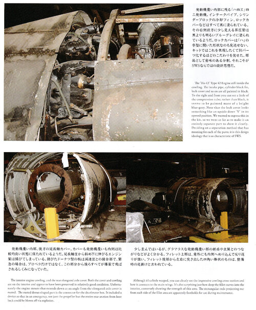
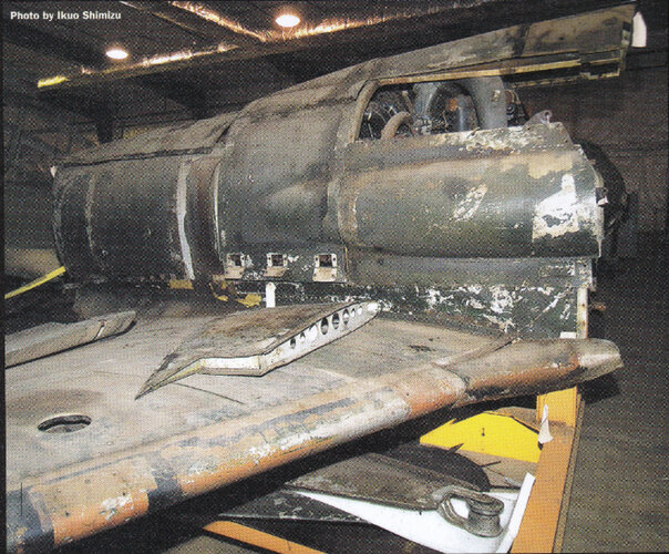
Source : SA SCALE AVIATION, VISUAL BIMONTHLY FOR SCALE AIRCRAFT MODELERS VOLUME 154, NOV 2023,
Source : SA SCALE AVIATION, VISUAL BIMONTHLY FOR SCALE AIRCRAFT MODELERS VOLUME 154, NOV 2023,
Attachments
-
 wing and supercharger air intake.jpg1.7 MB · Views: 96
 -
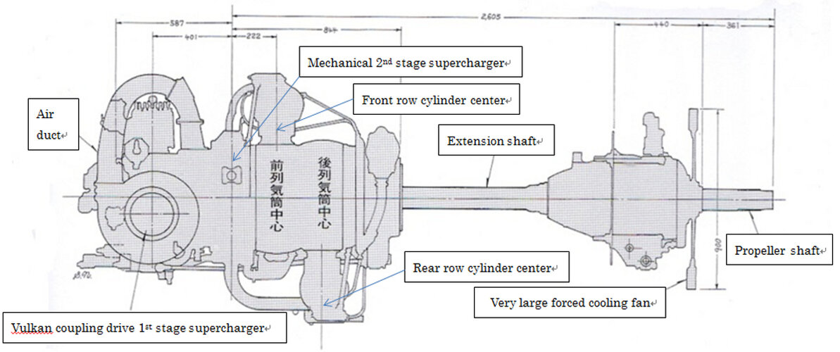
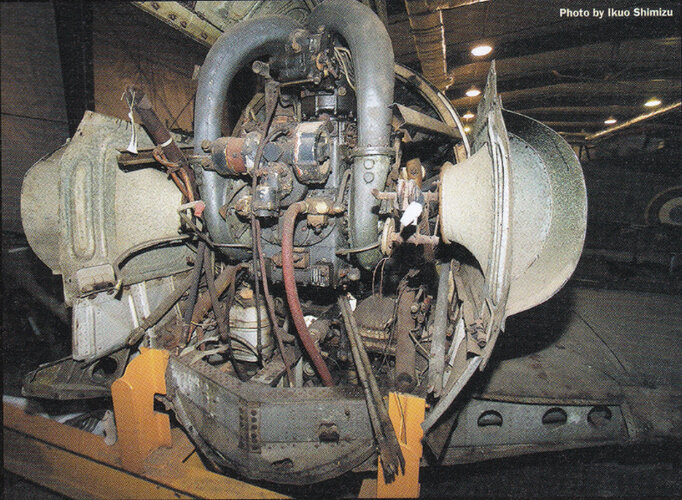 vulkan coupling drive supetcharger and air duct to second stage gear drive supercharger.jpg1.7 MB · Views: 95
 -
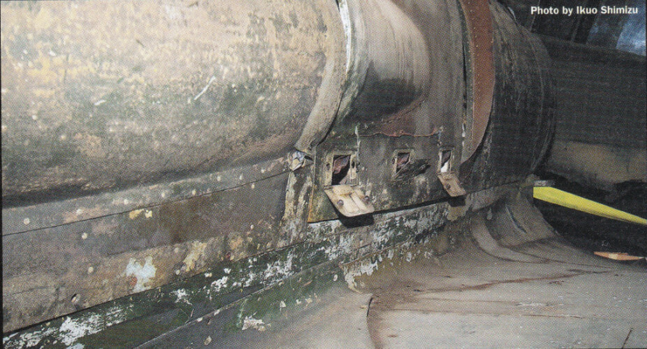 wing root.jpg1.3 MB · Views: 86
 -
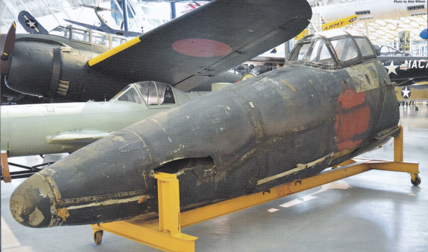 nose.jpg1.1 MB · Views: 70
 -
 SCALE AVIATION MAGAZINE.jpg450.8 KB · Views: 71
 -
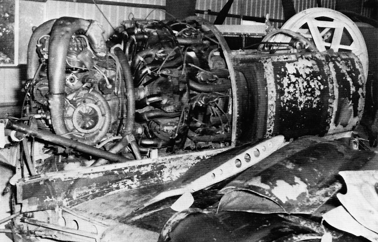 kyushu-j7w1-shinden-ha-43-42-engine.jpg396.8 KB · Views: 90
blackkite
Don't laugh, don't cry, don't even curse, but.....
- Joined
- 31 May 2007
- Messages
- 8,819
- Reaction score
- 7,716
I will inform this contribution to the museum.A small flat, the propeller blades are oriented in reverse as to brake the engine ...

blackkite
Don't laugh, don't cry, don't even curse, but.....
- Joined
- 31 May 2007
- Messages
- 8,819
- Reaction score
- 7,716
I don't know quantitatively, but I think that the cooling air intake of the Shinden fighter does not have a fence to escape the boundary layer, and the speed of the incoming air is slower than the flight speed. Therefore, I think that a large cooling fan will be needed to obtain the speed necessary to cool the engine of the Shinden. In addition, there is no intermediate cooler after the first-stage compressor, and the air duct to the second-stage compressor needs to be cooled, so a large cooling fan is required.
Hi Noveos,
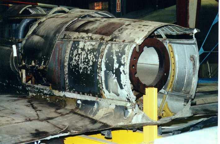
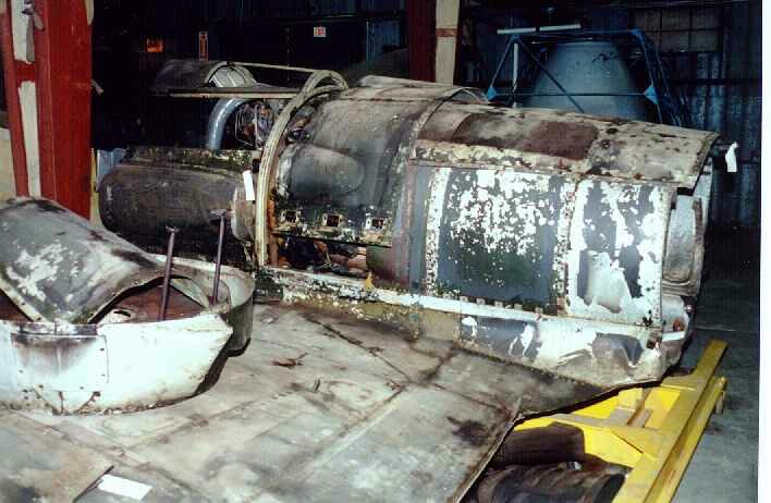
Not a silly question at all. I suppose the mounting is not only large, but also fairly substantial, as it has to transfer the torque loads between the engine and the propeller reduction gear mounted at just forward of the propeller that are induced by the driveshaft spinning at crankshaft speed.
Torsional vibration and fore-and-aft vibration of the engine-drive shaft-propeller system had been a serious problem on the Mitsubishi J2M Raiden ("Jack") fighter, which used an extension shaft with a tractor propeller, and I imagine the Japanese engineers learned from that. (See "The Zero Fighter" by Okumiya, Horikoshi and Caidin for a record of the J2M's problems.)
Another reason for a large "core" of the rear cowling might have been the internal aerodynamics, as you'd want to keep the air flow through the cowling as smooth as possible by avoiding abrupt cross section changes, but I imagine if that were the primary reason, the engineers might not have come up with the simple cylinder shape but something more streamlined.
Regards,
Henning (HoHun)
View attachment 713511
I’m not sure if this is a silly question, but why is the mounting for the cooling fan so large in diameter?
Not a silly question at all. I suppose the mounting is not only large, but also fairly substantial, as it has to transfer the torque loads between the engine and the propeller reduction gear mounted at just forward of the propeller that are induced by the driveshaft spinning at crankshaft speed.
Torsional vibration and fore-and-aft vibration of the engine-drive shaft-propeller system had been a serious problem on the Mitsubishi J2M Raiden ("Jack") fighter, which used an extension shaft with a tractor propeller, and I imagine the Japanese engineers learned from that. (See "The Zero Fighter" by Okumiya, Horikoshi and Caidin for a record of the J2M's problems.)
Another reason for a large "core" of the rear cowling might have been the internal aerodynamics, as you'd want to keep the air flow through the cowling as smooth as possible by avoiding abrupt cross section changes, but I imagine if that were the primary reason, the engineers might not have come up with the simple cylinder shape but something more streamlined.
Regards,
Henning (HoHun)
Thank you and @blackkite for the responses! It makes total sense that torsional vibration would be a serious concern. So does this "drum" looking mount rotate or merely hold the extension shaft in place?Hi Noveos,
Not a silly question at all. I suppose the mounting is not only large, but also fairly substantial, as it has to transfer the torque loads between the engine and the propeller reduction gear mounted at just forward of the propeller that are induced by the driveshaft spinning at crankshaft speed.
Torsional vibration and fore-and-aft vibration of the engine-drive shaft-propeller system had been a serious problem on the Mitsubishi J2M Raiden ("Jack") fighter, which used an extension shaft with a tractor propeller, and I imagine the Japanese engineers learned from that. (See "The Zero Fighter" by Okumiya, Horikoshi and Caidin for a record of the J2M's problems.)
Another reason for a large "core" of the rear cowling might have been the internal aerodynamics, as you'd want to keep the air flow through the cowling as smooth as possible by avoiding abrupt cross section changes, but I imagine if that were the primary reason, the engineers might not have come up with the simple cylinder shape but something more streamlined.
Regards,
Henning (HoHun)
Hi Noveos,
In the model picture you posted, it looks like it's a stationary structure to which the reduction gear housing is bolted. The front end probably is bolted directly to the engine housing.
(There are a lot of interesting diagrams in this thread, but I'm not sure any of them detail this particular aspect, so don't take my guess for the gospel ;-)
Regards,
Henning (HoHun)
Thank you and @blackkite for the responses! It makes total sense that torsional vibration would be a serious concern. So does this "drum" looking mount rotate or merely hold the extension shaft in place?
In the model picture you posted, it looks like it's a stationary structure to which the reduction gear housing is bolted. The front end probably is bolted directly to the engine housing.
(There are a lot of interesting diagrams in this thread, but I'm not sure any of them detail this particular aspect, so don't take my guess for the gospel ;-)
Regards,
Henning (HoHun)
Scott Kenny
ACCESS: USAP
- Joined
- 15 May 2023
- Messages
- 11,628
- Reaction score
- 14,305
I assume that the fan was spinning much faster than the prop RPM?Hi! Shinden propulsion system.
martinbayer
ACCESS: Top Secret
- Joined
- 6 January 2009
- Messages
- 3,397
- Reaction score
- 3,904
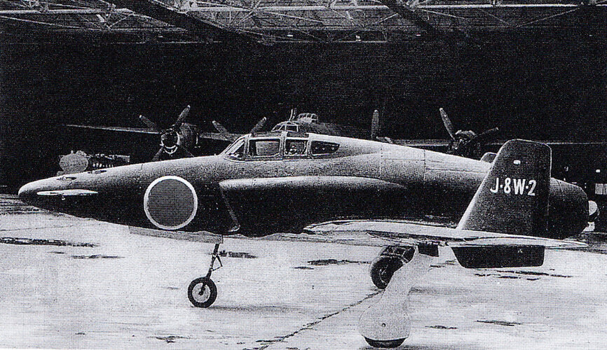
I vastly prefer the unbuilt jet variant anyway .
.blackkite
Don't laugh, don't cry, don't even curse, but.....
- Joined
- 31 May 2007
- Messages
- 8,819
- Reaction score
- 7,716
Similar threads
-

-

-
 Yokosuka (Yokosho/Yosho, Kugisho/Kusho) related topics on this forum
- Started by Stargazer
- Replies: 0
-
-
 IJN Specification 12-Shi (E12/E13, Reconnaissance Seaplane, 1937)
- Started by blackkite
- Replies: 25