- Joined
- 27 December 2005
- Messages
- 17,748
- Reaction score
- 26,410

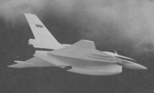
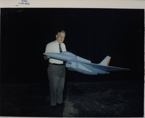
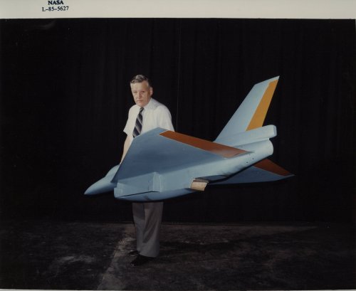
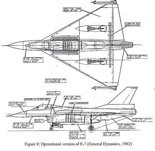
Jemiba said:I once found this photo in the net, unfortunately I haven't
the link anymore. The E-7 seems to be based on a vectored
thrust engine .
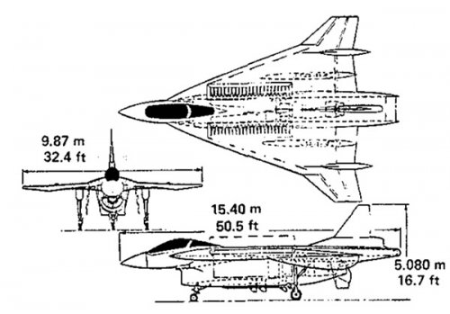
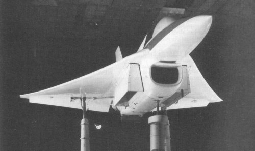
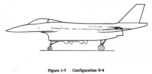
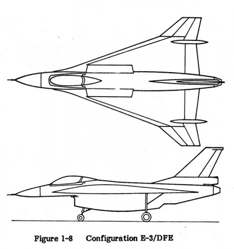
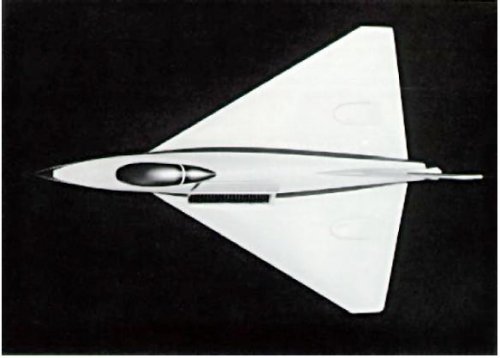
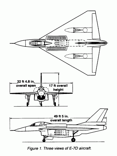
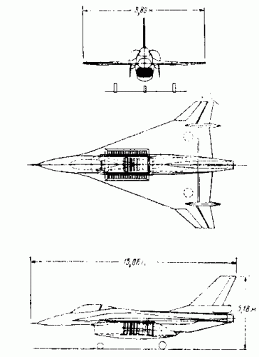
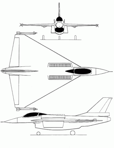
Interesting angle here. Cranked wing suggests maybe E-3/DFE?
Somewhat surprised in the past present document, they describe the AV8B, the key feature(to me) is the front nozzles are cold, the rear are hot - doesn't get a mention.Jemiba said:I once found this photo in the net, unfortunately I haven't
the link anymore. The E-7 seems to be based on a vectored
thrust engine .
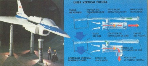
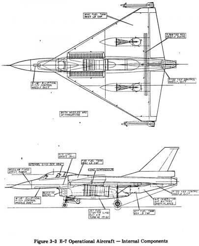
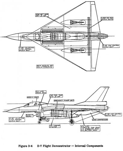
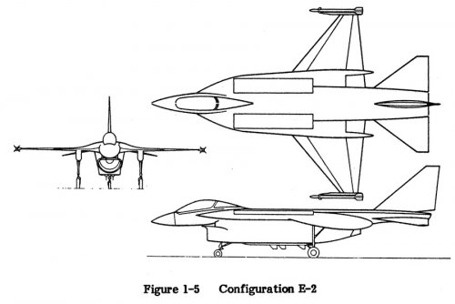
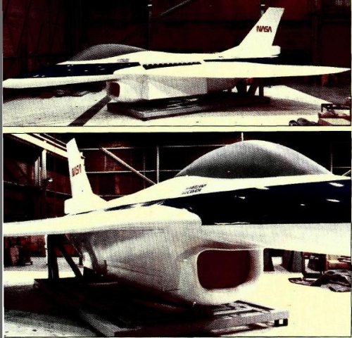
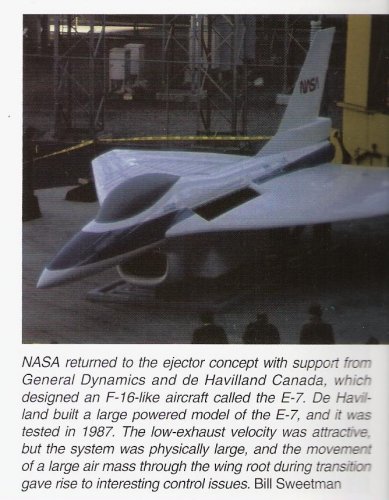
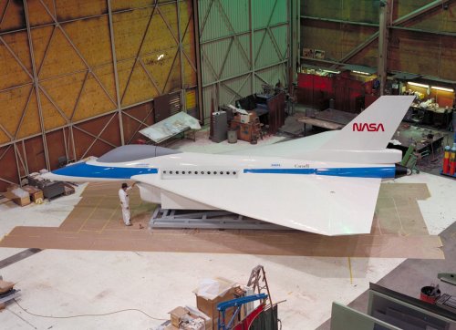
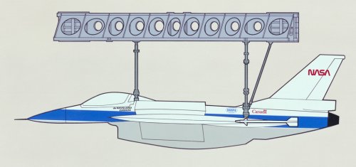
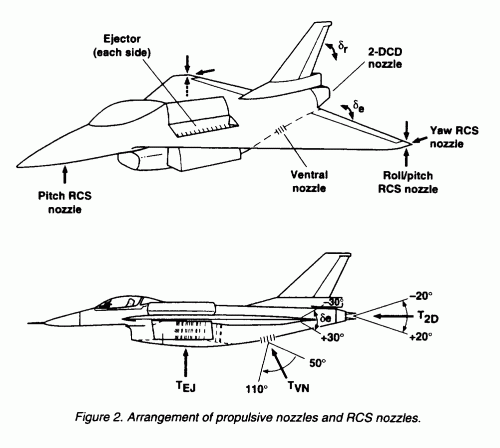
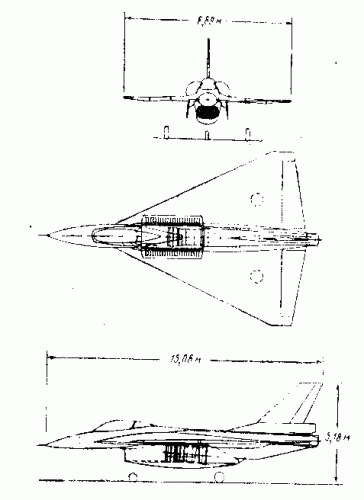
The E-7 VTOL concept relied on a thrust deflector at the rear and Thrust Augmented Ejectors near the front.
Air was diverted from the rear of the engine to the front via a long pipe and ejected down - balancing the thrust deflected at the rear.
There are some NASA PDFs on featuring the E-7 on the web:
V/STOL and STOVL Aerodynamic Performance:
http://ntrs.nasa.gov/archive/nasa/casi.ntrs.nasa.gov/19840014468_1984014468.pdf
VSTOL Concepts Past, Present and Future:
http://ntrs.nasa.gov/archive/nasa/casi.ntrs.nasa.gov/19840014464_1984014464.pdf
Wave-Drag and High Speed Performance of Supersonic Fighter Configurations:
http://ntrs.nasa.gov/archive/nasa/casi.ntrs.nasa.gov/19890000646_1989000646.pdf
Looks like a lot of interesting stuff in them - I just haven't had time for more than a quick browse.
Starviking
Yes seems to be a vestigial feature from the F-16E/"SCAMP" and later the "XL". The E-7A routed cool fan air forwards to the wing root ejectors, while the E-7D used a mixed flow (cool bypass air and hot core air) for the same effect.. nothing. Claims that the ejector could increase the fan flow by 50% seem (I say hesitantly) - overblown.. Sounds too much like a repetition ofthe failings of the XV-12A. The magical "entrainment" effect and getting more from less scuttled many concepts, particulary the Avro Canada efforts of the 1950-60. Even so, a very interesting concept if it could work.Interesting angle here. Cranked wing suggests maybe E-3/DFE?
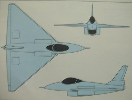
I just read this post. That appears to me to be a modified F-16XL converted into a demonstrator for the program, rather than building an entirely new airframe.
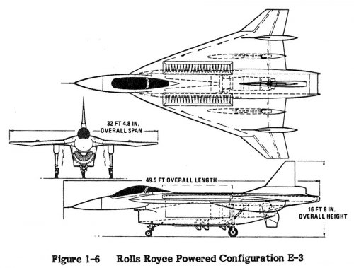
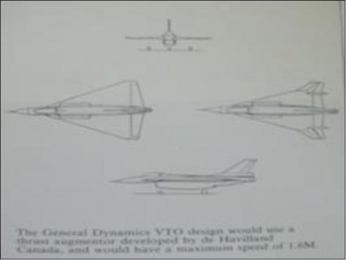
... E-7A: Part of US/Canadian ejector program. With Rolls-Royce "Spey" engine (possibly RB-168-25R Mk-202/3)...
Thanks for clarifying Apophenia.... E-7A: Part of US/Canadian ejector program. With Rolls-Royce "Spey" engine (possibly RB-168-25R Mk-202/3)...
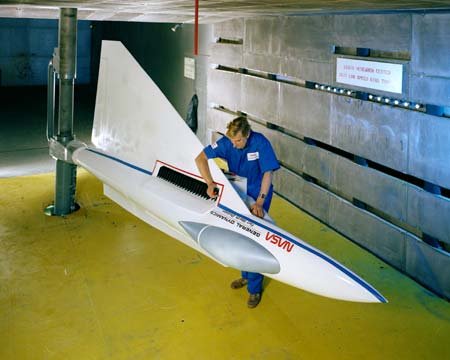
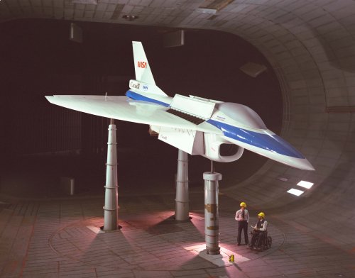
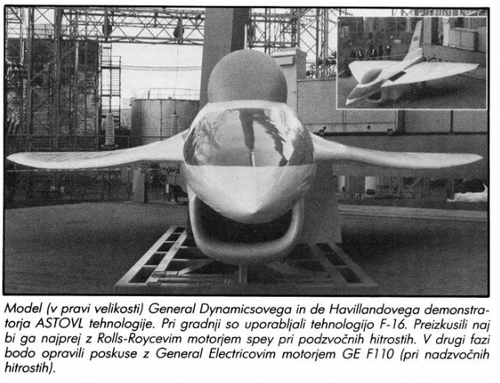
Under the US/Canada Focused Ejector Technology Program, the de Havilland division of Boeing Canada built a full-scale wind tunnel model of the E-7A. As you say, it was that model which had powered generated by "a Rolls-Royce 'Spey' engine obtained from a previous research program."*
So, the Spey was something that NASA had in stock. Rather than ex-RAF Phantom engines, the powerplant would more likely be the Spey MK 801-SF (Split Flow) - a Spey Mk 611 previously modified by Rolls-Royce (Canada) for NASA's AWJSRA (V/STOL Buffalo) programme. Removing that engine's transition section, colander-plate connector, and bifurcated Pegasus Mk.5 nozzles wouldn't have been difficult.
BTW: the plan for the full-scale powered wind tunnel model was to return it to DHC for a rebuild into a Phase II configuration with an F110 replacing the Spey and a 2D-CD nozzle to represent the E-7D rather than an E-7A.
* Configuration E-7 Supersonic Fighter/Attack Technology Program, John E. Jenista & David S. Bodden, General Dynamics Fort Worth Division, 1988, page 3
I don't think it will be going anywhere anytime soonSo apparently NASA organized an auction for a whole load of experimental aircrafts and this guy bought the E7 model.
View: https://www.youtube.com/watch?v=YBxfFbPpEUE
Pardon the ancient response, but I suspect that a lot of the failure with the XFV-12 augmentors was the rough interior of the pipes. For cost reasons the insides of the pipes weren't cleaned up, when the part of the pipes that needed to be smooth to not reduce airflow was the interior, not the exterior!E-7 was yet another design intended to use exhaust-driven ejectors for vstol lift. After the fiasco of the XFV-12A, following on the failure of the XV-4A (it had to be rebuilt as the XV-4B with a battery of lift jets to do any vstol ops), you'd think people would finally realize that there's a fatal disconnect as you scale up from wind tunnel to full scale.
Do you have any references? Or is this pure speculation?Pardon the ancient response, but I suspect that a lot of the failure with the XFV-12 augmentors was the rough interior of the pipes. For cost reasons the insides of the pipes weren't cleaned up, when the part of the pipes that needed to be smooth to not reduce airflow was the interior, not the exterior!
I get that the prototype was built on the super cheap, but having the thing fail possibly because the builder cheaped out in the wrong place just annoys me to no end.
There's comments in the XFV-12 thread about the inside of the pipes being rough.Do you have any references? Or is this pure speculation?
 opular Mechanics edition Argentinean Nov. 1989)