- Joined
- 28 October 2006
- Messages
- 1,004
- Reaction score
- 102

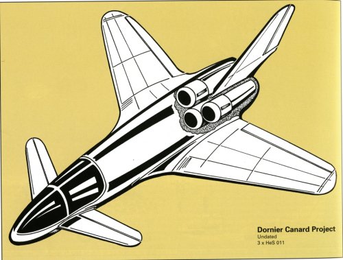
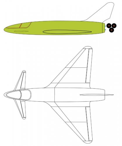
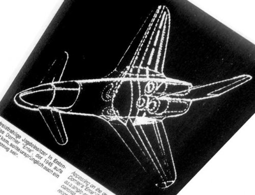
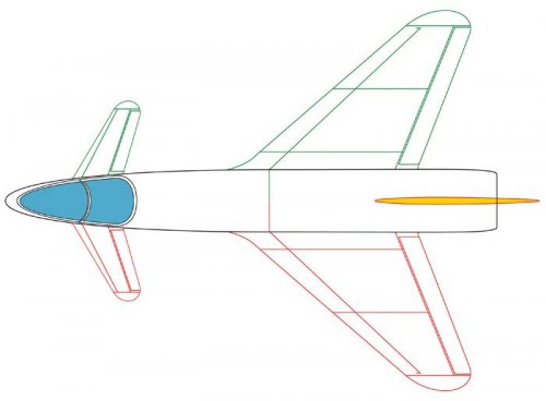
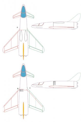
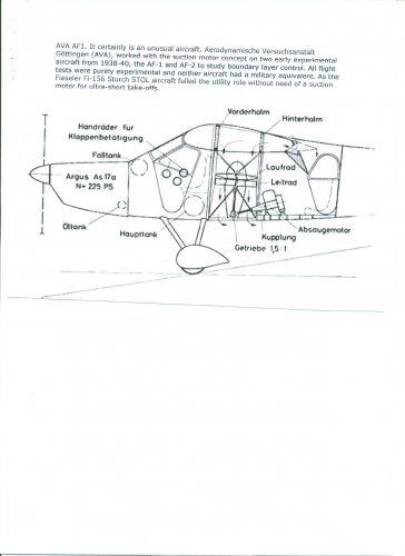
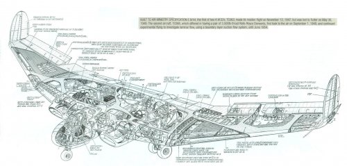
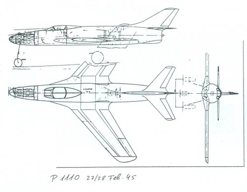
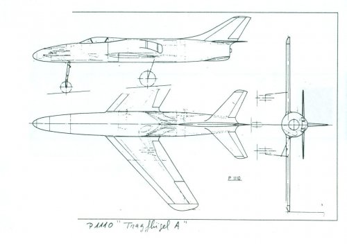
the intake would have been
a slot across the wing and fuselage, which additionally served as boundary layer
suction.
Flitzer said:Thanks Jemiba.
As you mentioned it may have been a racer, I wonder as a fighter were the armaments may have been placed? There seems precious little room to spare with the extreme forward cockpit.
Many thanks
P
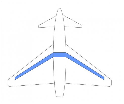
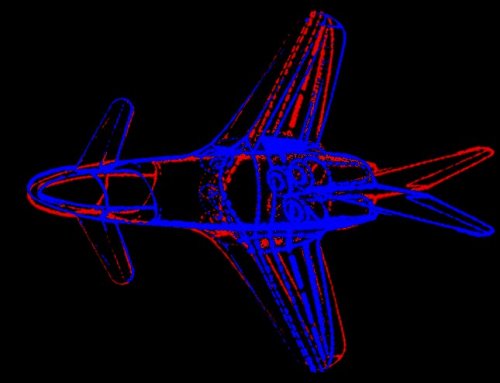
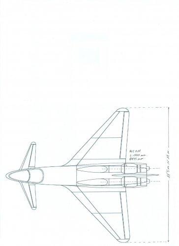
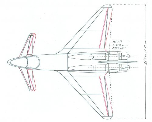
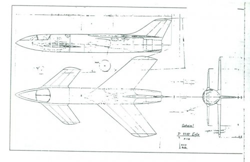
Stargazer2006 said:Jens, I think your drawing has wings that are too long and/or too narrow. Just my impression.
")
Justo Miranda said:Autocorrection for 11,5 m. span
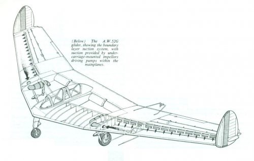
Flitzer said:As a point of interest, have any aircraft been built and successfully put into service using wing boundary layer suction intakes?
Flitzer said:As a point of interest, have any aircraft been built and successfully put into service using wing boundary layer suction intakes?Many thanksP
alfakilo said:Flitzer said:As a point of interest, have any aircraft been built and successfully put into service using wing boundary layer suction intakes?Many thanksP
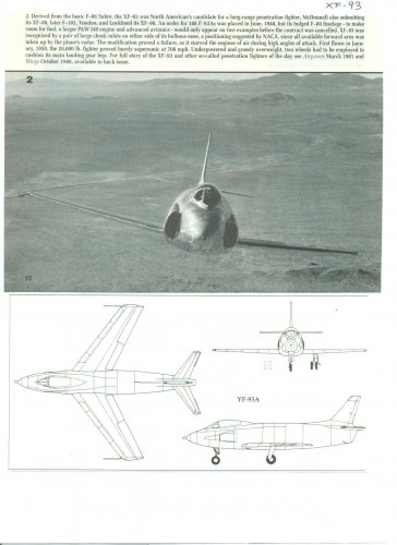
Perhaps the lessons learned from the XF-93 and its unique inlet design might be helpful to your question. While the NACA inlet theory "worked", it apparently didn't "work" well enough...and was replaced by conventional intakes.