Caproni Ca.183

Re: Ca- 183bis

Blacklynx09 said:
I actually created that forum post myself. XD

As I promised you Blacklynx,

I will search on a more Info about it,but that needs time.
 
Re: Ca- 183bis

I greatly appreciate it and will be looking forward to any information.
 
Re: Ca- 183bis

What I am most interested in is what skybolt refers to as the 'Caproni Technical Descriptions Brochure'.
 
Re: Ca- 183bis

A more Info about Ca.183.
 

Attachments

  • 2.png
    2.png
    379.8 KB · Views: 535
  • 3.png
    3.png
    155.6 KB · Views: 483
  • 4.png
    4.png
    292.6 KB · Views: 560
Re: Ca- 183bis

I thank you for your work Hesham.
 
Re: Ca- 183bis

Blacklynx09 said:
I thank you for your work Hesham.

At your service Sir,and if I find anything more I will send it.
 
Re: Ca- 183bis

Everything is known on the 183 will be in ISP, IF it appears early next year.
 
Re: Ca- 183bis

Skybolt said:
Everything is known on the 183 will be in ISP, IF it appears early next year.

Wow,a good news my dear Skybolt.
 
Re: Ca- 183bis

Skybolt said:
Everything is known on the 183 will be in ISP, IF it appears early next year.

Is there a realistic chance of this? I'm sure I'm not the only one who would be very glad if this long anticipated book finally came out! :)
 
Re: Ca- 183bis

Skybolt said:
I'll post complete data later, for now I only say that the gun on the engine was a 20 mm one like the other four, not a 30 mm. Lot of legends on this project, as you see. BTW, I'm not convinced that the DB-605 transmission shaft could even house a 30 mm caliber gun...

————————————————————————————-
Most motor-cannons operate completely outside the engine, ergo no need to worry about compatibility with the crankshaft. They will not fire through the middle of the crankshaft. Often they nestle into the V between cylinder banks.

Instead, most motor-cannons only fire through the propeller speed reduction unit. Since the PSRU offsets the propeller from the crankshaft, the cannon barrel has no need to penetrate the crankcase. . Since the contra-rotating propellers needed a completely new PSRU it would be easy to specify a 30 or 37mm cannon - at the start of the project - and design the new PSRU around the larger cannon.
 
Last edited:
Greetings

In short: this plane is a motorjet fighter serived from an earlier Campini N.1. I knew 183 existed for some time, but I only recently discovered that it was, as some sources claim, 80% finished at some point in late 1944 or early 1945. The prototype was then destroyed in allied bombardment and was forgotten.

I searched several sites for pictures or any evidence the partial prototype existed, but the only evidence I managed to find is a blueprint of some sort.

https://forum.warthunder.com/uploads/monthly_2017_05/post-578478-0-30900000-1464549951.jpg.a24e5adc5126ac94ec5d50b6cebb5ed1.jpg

Question: do pictures of the prototype exist?

Kind regards :)


Topics merged
 
From Ailes 7/1948,

the Caproni Ca.380.
 

Attachments

  • 1.png
    1.png
    473.2 KB · Views: 262
From Ali Nuove 6/1960,

the Ca.380 Corsaro and its variants ?!.
 

Attachments

  • 1.png
    1.png
    688.6 KB · Views: 220
  • 2.png
    2.png
    516.1 KB · Views: 220
  • 3.png
    3.png
    209.5 KB · Views: 327
From Aerei Nella Storia 4-5/2009.
 

Attachments

  • 3.png
    3.png
    608.3 KB · Views: 236
  • 2.png
    2.png
    575.1 KB · Views: 213
  • 1.png
    1.png
    531 KB · Views: 257
1. Press d’aria dinamico (Dynamic air press)
2. Compressore centrifugo ausiltario a due stad (two-stage auxiliary centrifugal compressor)
3. Refrigeratore dell’ aria di alimontazione (Power supply air chiller)
4. Compressore centrifugo ausiltario (auxiliary centrifugal compressor)
5. Compressore del motore DB-605A (DB-605A engine compressor)
6. Motore FIAT DB-605A azionante eliche tripala controrotanti (FIAT DB-605A engine counter-rotating three-blade propellers )
7. Motore ausiltario FIAT A.30 (auxiliary engine FIAT A.30)
8. Compressore assiail (ventola intubala) (axial compressor (Duct fan))
9. Radiatore dell acqua (water radiator)
10. Iniettore combustibile (fuel injector)
11. Bruciatore (burner)

Schema Propulsivo del Ca.183 bis (Propulsive scheme of the Ca.183 bis)
 

Attachments

  • propulsive scheme of the Ca.183 bis.jpg
    propulsive scheme of the Ca.183 bis.jpg
    512.3 KB · Views: 10
  • my guess for this system.jpg
    my guess for this system.jpg
    318 KB · Views: 9
FIAT A,30 engine.

FIAT A.30
The Fiat A.30 R.A. was an Italian water-cooled aircraft engine from the 1920s, built in large numbers and serving with several air forces up to the beginning of World War II.
Manufacturer: Alfa Romeo
Developed: 1920s
Type: Water cooled 60° upright V-12
Bore: 135 mm (5.31 in)
Stroke: 140 mm 5.51 in)
Displacement: 24.0 L ( 1,464 cu in)
Length: 1.751 m (68.94 in)
Width: 653 mm (25.71 in)
Height: 935 mm (36.82 in)
Dry weight: 480 kg (1,060 lb)

Performance:
Power Output:
– Normal: 600 hp at 2,000 rpm at sea level
– Take-Off: 800 hp at 2,900 rpm.
Compression ratio: 8:1
Fuel consumption: 0.322 kg/kW/h (0.529 lb/hp/h)
 

Attachments

  • FIAT_A.30_R_HP_600-850.jpg
    FIAT_A.30_R_HP_600-850.jpg
    38.2 KB · Views: 18
1. Press d’aria dinamico (Dynamic air press)
2. Compressore centrifugo ausiltario a due stad (two-stage auxiliary centrifugal compressor)
3. Refrigeratore dell’ aria di alimontazione (Power supply air chiller)
4. Compressore centrifugo ausiltario (auxiliary centrifugal compressor)
5. Compressore del motore DB-605A (DB-605A engine compressor)
6. Motore FIAT DB-605A azionante eliche tripala controrotanti (FIAT DB-605A engine counter-rotating three-blade propellers )
7. Motore ausiltario FIAT A.30 (auxiliary engine FIAT A.30)
8. Compressore assiail (ventola intubala) (axial compressor (Duct fan))
9. Radiatore dell acqua (water radiator)
10. Iniettore combustibile (fuel injector)
11. Bruciatore (burner)

Schema Propulsivo del Ca.183 bis (Propulsive scheme of the Ca.183 bis)

This was also my guess, it makes totally sens to place the water coolers behind the compressor, so that the cooling heat can be used for generating thrust. The intercoolers are placed in front of the compressor where the temperature of the air flow is cooler.

A couple of years ago I did some calculations and came to the conclusion, that a "mild thermojet" with low compression ratio and heat only from the cooling/charging+ exhaust system can be an efficient approach for an high altitude plane. Of course, most of the power would come from the propellers.
 
I guess this is quite exact.

The propulsive sheam in #59 indicates, that there might have been a differential which drives the superchagers with increasingly speed with increased torque. Such drives have been used in some truck engines long time ago, it would make sense because it enables a variable super charger drive.
 
Hi! Almost same scale.
 

Attachments

  • Ca.183 bis and C.205.jpg
    Ca.183 bis and C.205.jpg
    146.6 KB · Views: 16
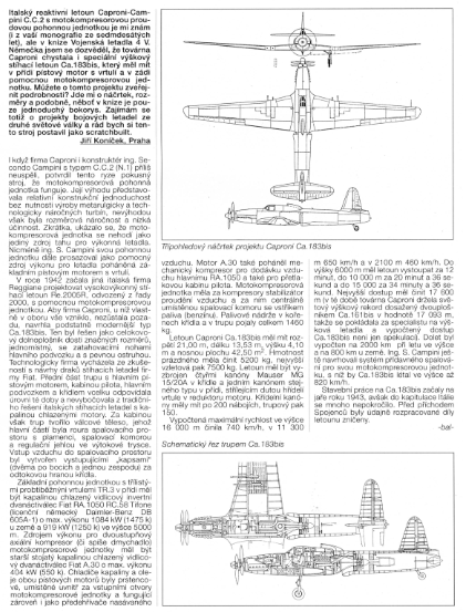
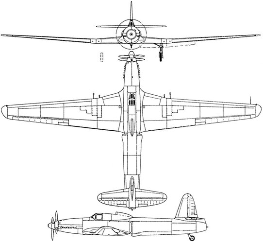
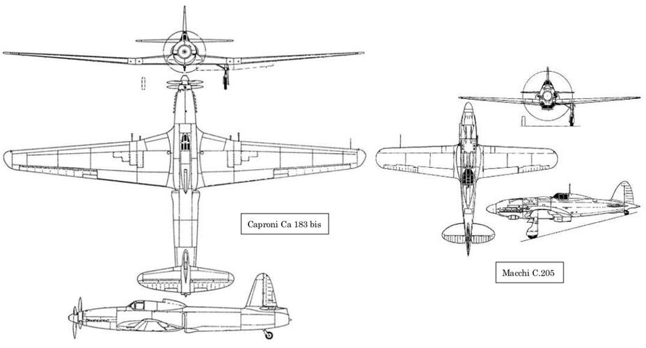
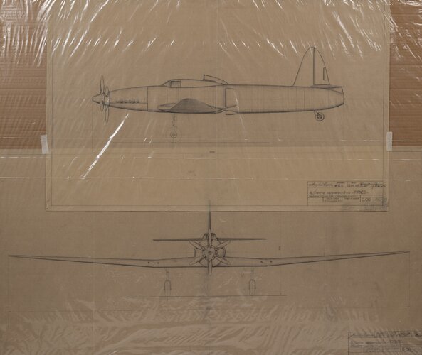
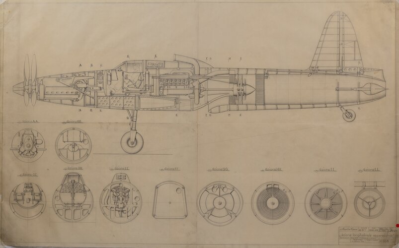
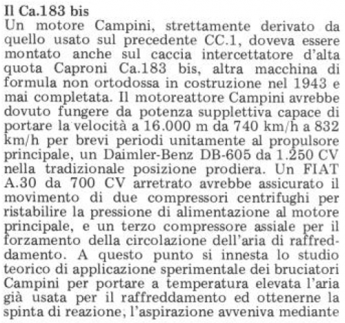
certainly experienced with the project of the high-altitude fighter Ca,183 BIS. Designed by Caproni technicians, it was an all-metal monoplane aircraft with a retractable carriage and fixed tail wheel.

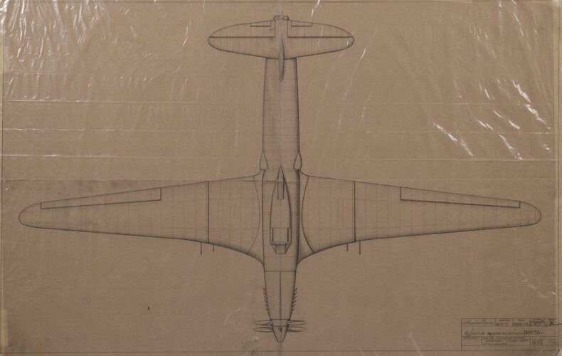
13.53 m long, 4.10m high, it is equipped with a low wing with a large aspect ratio with a trapezoidal shape and rounded ends.

The wing was clearly oversized so that a wingspan of 21m was combined with a wing area of 42.50sqm.

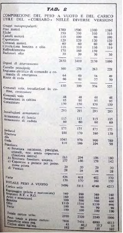
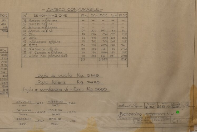
Fuel tanks were housed in the capable wings. The aircraft was designed as a single-seat daytime aircraft and was armed with five 20mm cannons four of which are in the wings, and one in the engine firing through the propeller shaft.

The wing guns were equipped with 800 rounds, while the cannon-engine had 150 rounds in the magazine.

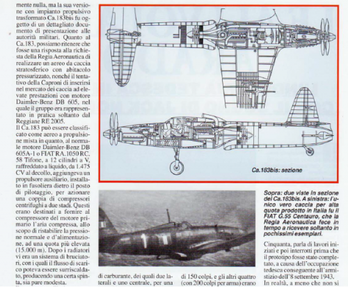
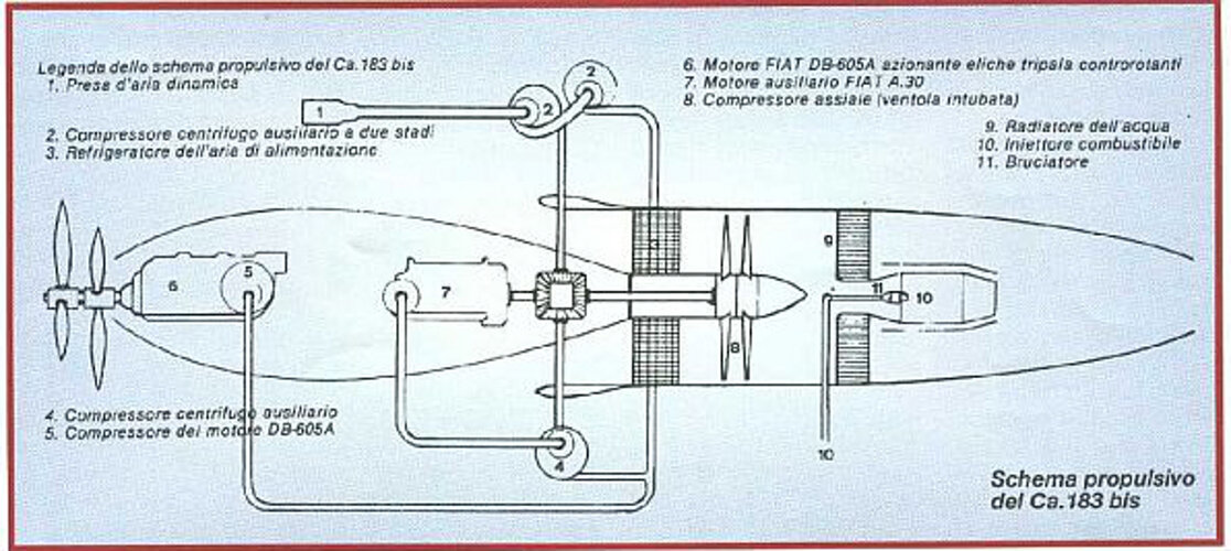
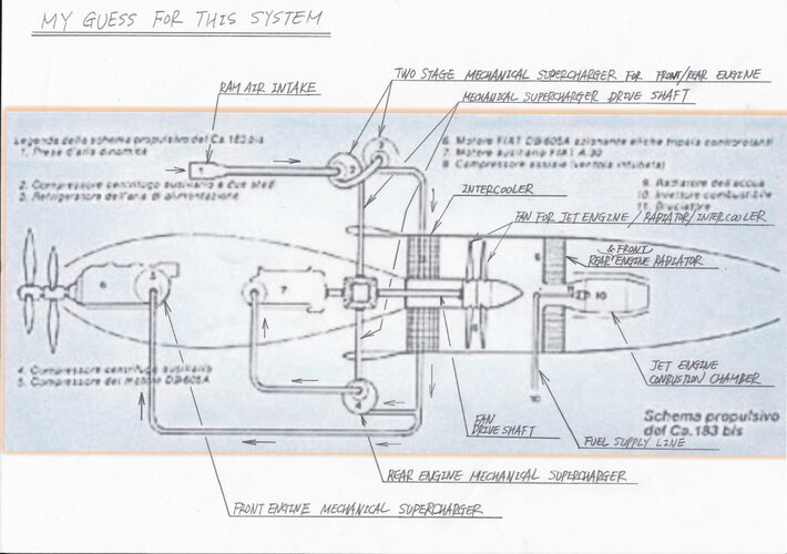
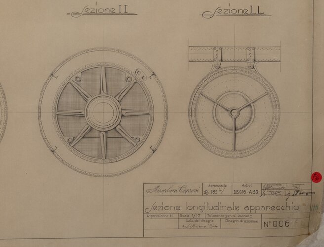
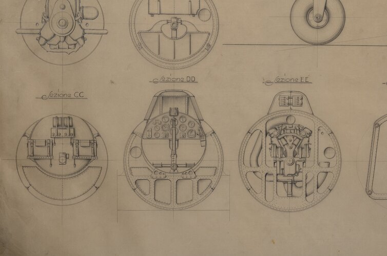
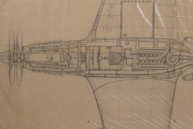
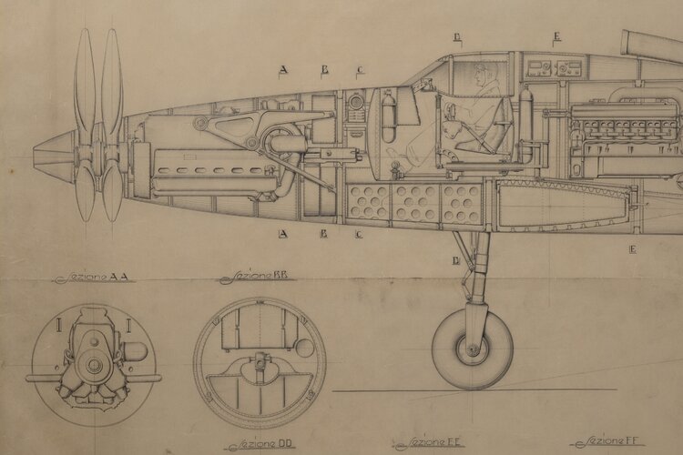
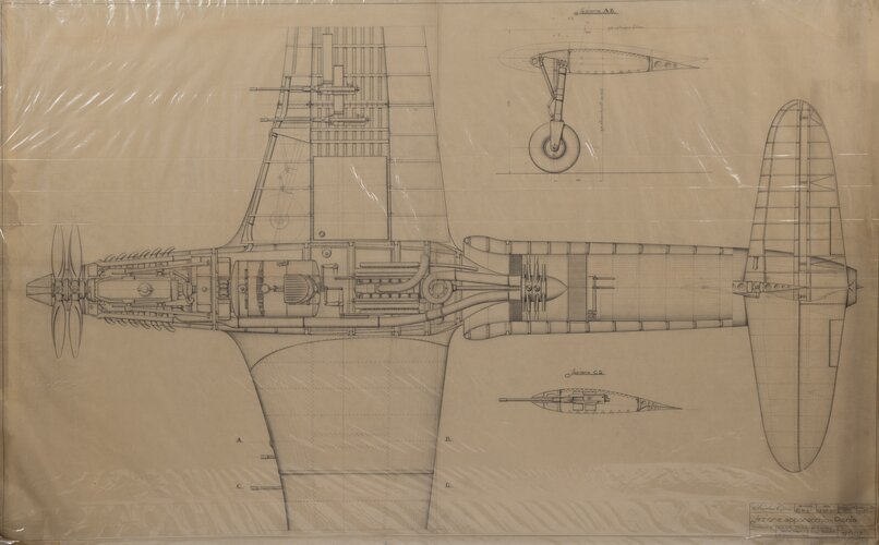
The fuselage of the Ca.183 BIS was intended to be built in two sectors.

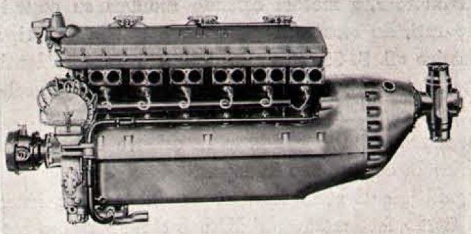
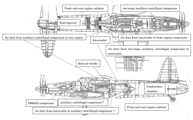
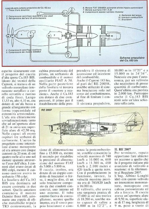
The front one contained the Daimler Benz 605 engine, pressurized driver's cab, a fuel tank and the FIAT A 30 auxiliary engine.

At the rear of the fuselage was the jet engine.

The Ca.183 was also equipped with two compressors, the first to restore the supply pressure up to 15000m, while the second to restore the FIAT engine feeding pressure from 3000 to 5800m.

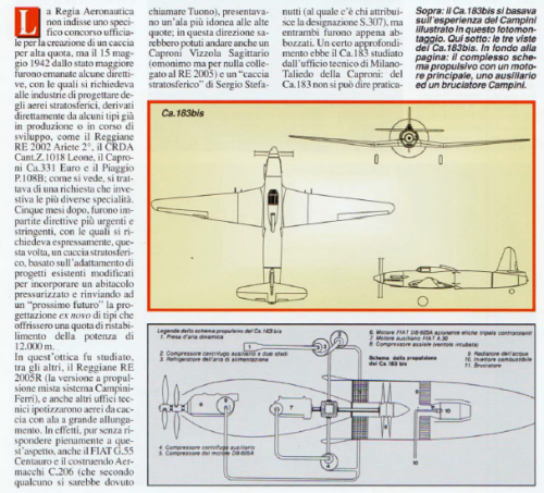
The fighter, moreover, was equipped with a double burner duct or perhaps, better to say, a single burner composed of two concentric ducts, one internal and one external.

The outer tube served as a ignition and fuel injection system was convinced.

The Caproni 183 bis, like the RE 2005R, would also have used the burner system only during combat, in order to limit consumption.

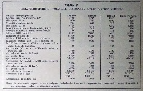
The propulsion system, without aftercombustion, would have allowed the maximum speed of 740km/h at 16000m, 660km/h at 11300m, 460km/h at 2100m and 420km/h at zero altitude.

With the afterburner running, however, the expected top speed was 780/820km/h at 16000m.

The aircraft, which had a practical ceiling of 17600m and a theoretical 10000m in 10'20" and at 15000m in 34'34".

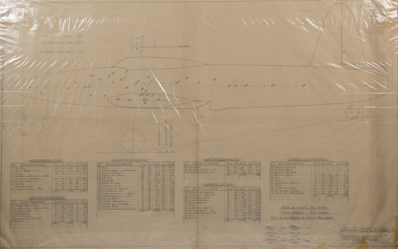
The autonomy was remarkable, for an aircraft that required large quantities of fuel.

The latter was expected to take 2000km. Unfortunately, even the Ca.183 bis remained only an idea sketched on paper.
 

Attachments

  • ca183_bis.jpg
    ca183_bis.jpg
    176 KB · Views: 10

Similar threads

Please donate to support the forum.

Back
Top Bottom