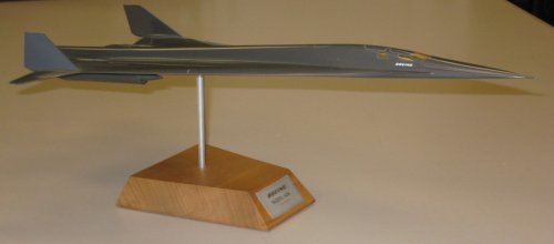
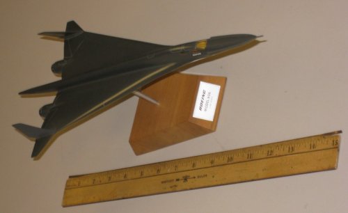
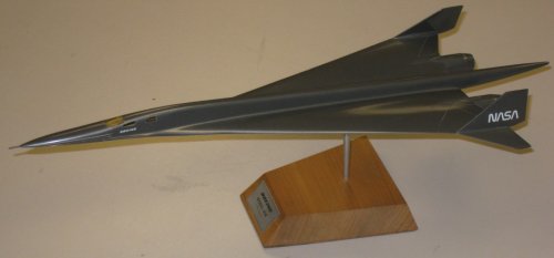
Great find with the Boeing Model 985 Micro-Fighter study!! (and just as impressive was the Airborne Aircraft Carrier C-5 / B747!!)
You know as much as it may seem crazy- both the concept and the size of the Model 985 Micro-Fighter, I am sure that the argument was the same for the General Dynamics F-16, when the USAF first had its concept put before it - especially so when one considers the then trend of ever increasing size and weight of that generation fighter/fighter-bomber designs!
If I may
I wish to highlight some of the things that gained my attention and get the forums feed back.
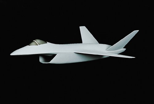
Evaluation led to the definition of 1980 IOC and 1985 IOC concepts for Micro-fighter Airborne Aircraft Carrier Systems.
Do you think this OIC dates was attainable?
Launch stations located outside the ground radar coverage require fighter
interdiction radii of 100 to 300 n.mi.
Does this seem an adequate standoff/launch range?
And if it had of been put into service (both Micro-Fighter and Airborne Aircraft Carrier) - would the likes of the Soviet/Russian S-300 SAM have made it obsolete very quickly????
summarizes the primary characteristics of the C-5A and 747F
when modified to the AAC configuration. The C-5A lacks endurance for multiple
sorties from each fighter. Modification to the 747 requires more weight for
the desired arrangement for fighter handling. Both designs can be made to
carry 10 fighters with space for on-board rearming but the C-5A loses some of
it capability to carry outsize cargo.
I can not but help wonder how much difference the Boeing CX-HLS design submission (the one the Air Force wanted!!) would have made over the Lockheed C-5 design???
turnaround Including rearming (of Micro-Fighter), is estimated to require 10 minutes per airplane.
Impressive!
Personnel requirements are 44 per airplane (Airborne Aircraft Carrier): an AAC (Airborne Aircraft Carrier) crew of 12, MF (Micro-Fighter) squadron of 14 and 18 supporting specialists.
Very interesting figures!
Operation of ten fighters in combat situations from a high altitude base
requires pressurized crew compartments and hangar decks. The launch and
recovery bays become airlocks to transfer tile fighters between environmental extremes
A potential major operational and safety factor!
Almost 'Battlestar Galactica' sounding.
With this capability recovery operations for mission aborts could be
initiated as early as 7 minutes after initial launch. A wide range of mission
times are probable. Intercept missions range from 10 to 24 minutes. Lo-level
strike missions range from 17 to 88 minutes and combat air patrol could be up
to 2.4 hours. The carrier has payload capability for at least three sorties
per fighter. Resulting time on station could range to 8 hours for all combat
air patrol.
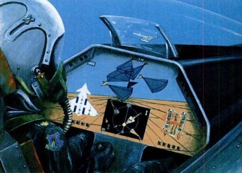
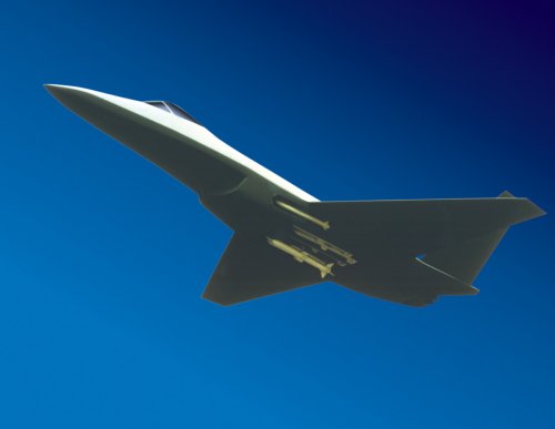
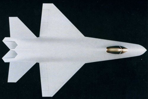
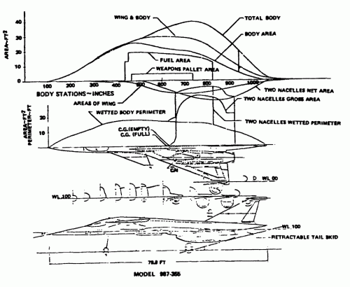
Advanced Short Range Missile –
Two internally carried, tube launched, dogfight missiles are
postulated for the 1980 Micro-fighter. A wingless configuration with
vectored rocket thrust for high maneuverability and a body diameter
similar to AIM-9 or Zuni is considered feasible. Missile exhaust gases
are ducted overboard (open tube launch). Look-before-launch capability is provided by projecting the missiles guidance section through the wing leading edge frangible ports.
Sound like an impressive missile system - way before its day.
Does anyone have any information on this air-to-air missile?
Was it an actual program?
Was it intended only for the Micro-Fighter?
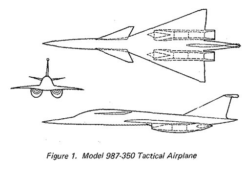
Two 1765 lb. ‘Smart bombs’ have been chosen for the primary air-to-ground mission. A folding fin derivative of this modular weapon is shown carried tangent at the wing-body intersection. Additional weapon carriage hard points are provided under each wing just inboard of B.L.46.5 to accommodate a variety of weapons. Potential performance gains resulting from wing-body intersection stores carriage should be evaluated during external store development and/or selection for the advanced technology Micro-fighter.
Again was there such a program as this 'Modular Weapon System' which is spoken about so much in the study?
I must say I do like the concept!!
A 1980 IOC Multi-Purpose Strike System (MPSS) would beast employ 10x747 AAC + 1x 747 AWACS. This complement provides 100 fighters (approximately 4 squadrons) for deployment to Europe in 8 hrs. from alert - on station and ready for combat with fighter crews rested and briefed.
Sounds like a Boeing salesman delight!
Although I would not dought or question this capability if the chance arrived!
Do you think the MF/AAC concept could have worked??????
Looking forward to anythink else that comes to light regarding this Micro-Fighter / Airborne Aircraft Carrier concept and studies!!!!!!!!!
Regards
Pioneer