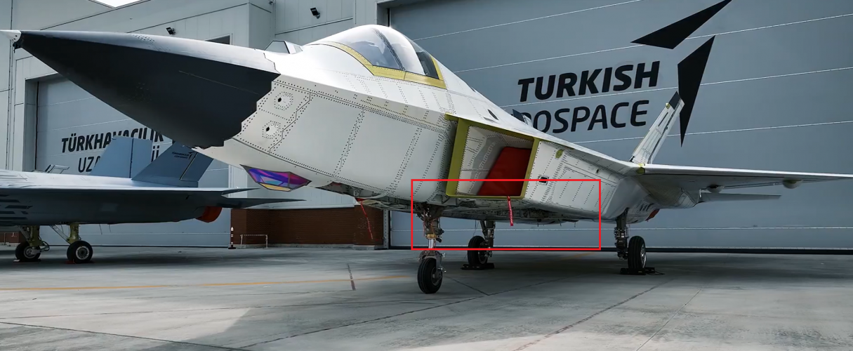
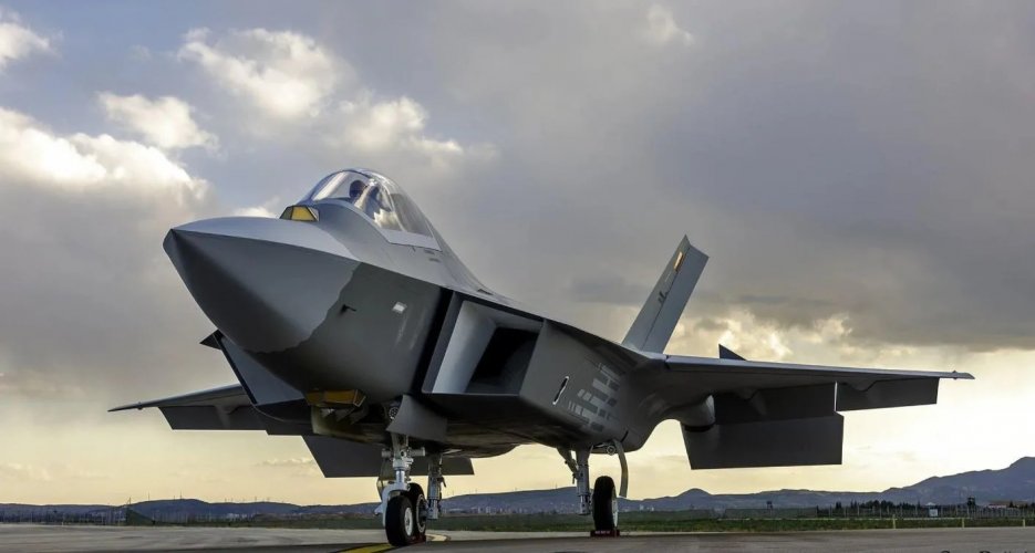
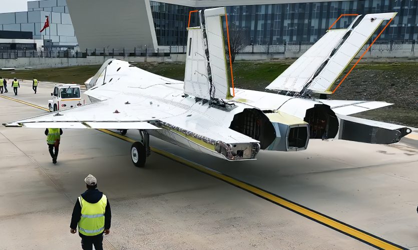
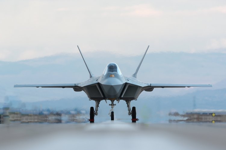
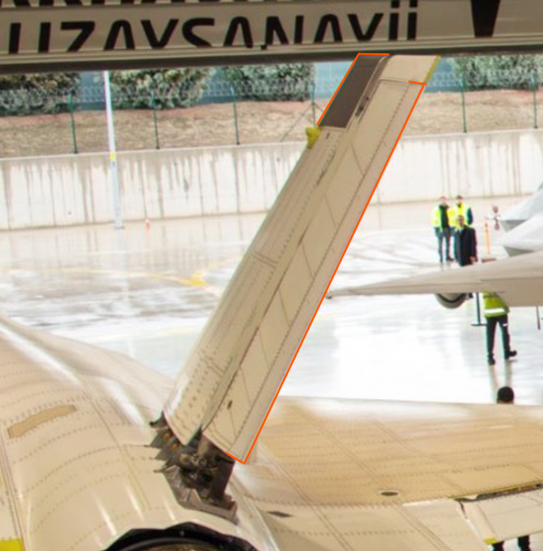
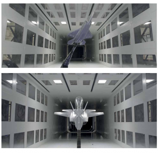
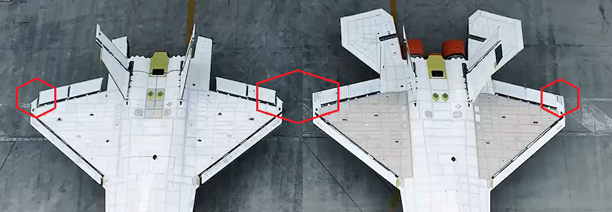
I think the position on the nacelles is necessary to ensure that they wouldn't be directly hit by the vortices of the LERX.
I was thinking/hoping that the adjustment of the intake had also the reason to direct the vortices a bit further away of the vertical stabilizers.
Therefore generating more wiggle room to fix them beside the nacelles - reducing maybe some overall height and shield some of the heat-signature.
 
Damn, each passing day I'm becoming more and more Kaan-sexual... o_O (Who would've thought?)
------------------------------------------------------------------------------------------------------------------------------------------------------
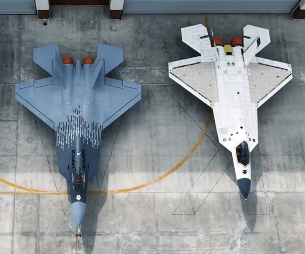
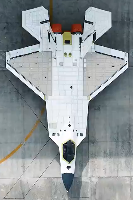
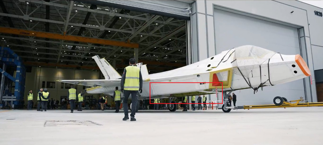
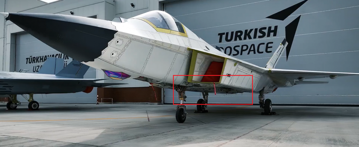
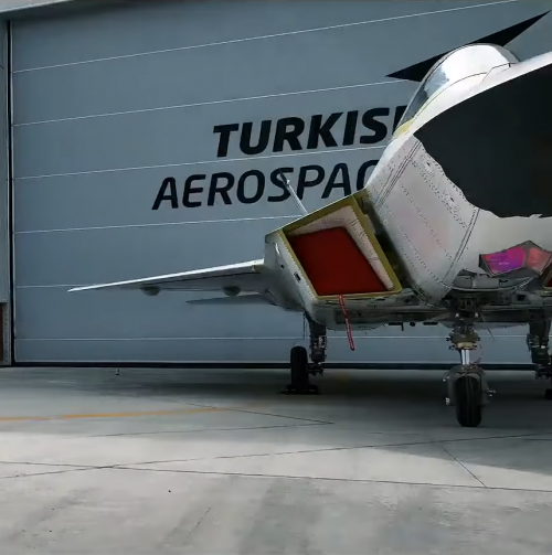
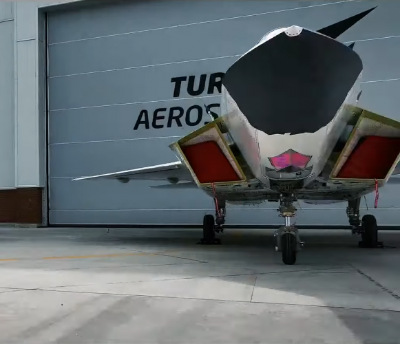
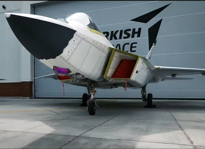
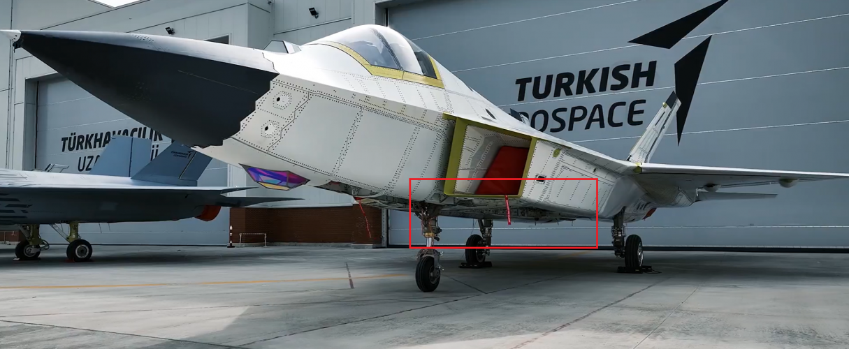
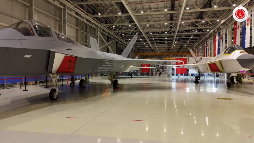
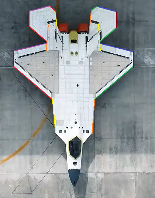
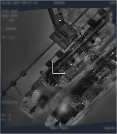
Holy crap, you can clearly see the door-less Belly IWBs of the Static Test Airframe...

(EDIT: And here's the P1: )
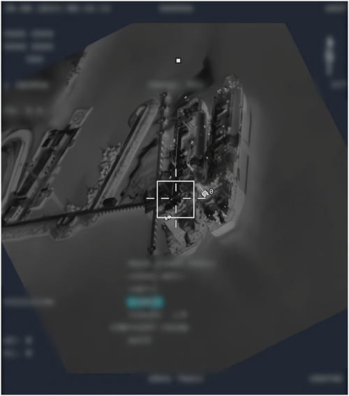
They're too transparent, they could've at least sensored it for a while...
 

Attachments

  • HBqxnYtW0AA7eUJ.png
    HBqxnYtW0AA7eUJ.png
    1.2 MB · Views: 695
  • Screenshot 2026-02-21 104503.png
    Screenshot 2026-02-21 104503.png
    2 MB · Views: 949
Last edited by a moderator:
will KAAN have 4 IWBs? two side bays and two tandem bays on the centerline? or will it be three?
There is definitely a side-by-side config on P1.
On another topic, we really don't appreciate the amount of composites used in KAAN enough.
 

Attachments

  • 1771675537665.png
    1771675537665.png
    618.5 KB · Views: 190
  • 1771675567410.png
    1771675567410.png
    649.9 KB · Views: 163
  • 1771675604067.png
    1771675604067.png
    869.3 KB · Views: 179
looks like its two side by side bays on the bottom. There were people here that were adamant its two tandem bays like on the Su-57.
Tbf, that was the general consensus three years ago, based on the information we had at the time.

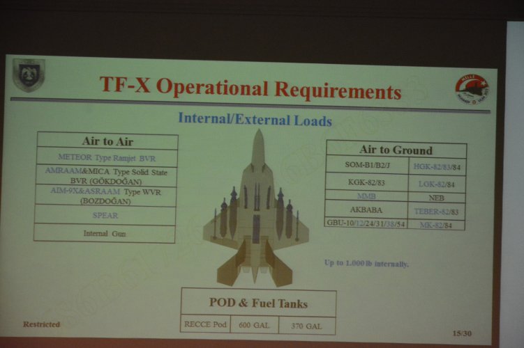
This slide was presented 5 years ago by the Air Force during Anatolian Eagle '21:

Clearly, lots of changes were happening even by then and the slide was already outdated during its display. (Which we kind of speculated at the time!)
 

Attachments

  • 1000083241.jpg
    1000083241.jpg
    385.6 KB · Views: 340
Last edited by a moderator:
Tbf, that was the general consensus three years ago, based on the information we had at the time.

This slide was presented during Anatolian Eagle '21:
Not unlikely P0 is exactly that configuration. Which is why after election there was little point even testing it.
 
Not unlikely P0 is exactly that configuration. Which is why after election there was little point even testing it.
Exactly. P0/GTU-0 (Designated as: Development Test Unit-0) was precisely that – an engineering unit built to physically validate whether theoretical calculations and designs could be translated into functional hardware.

As you noted, the design shown on the slide corresponds exactly to the P0 configuration.
 
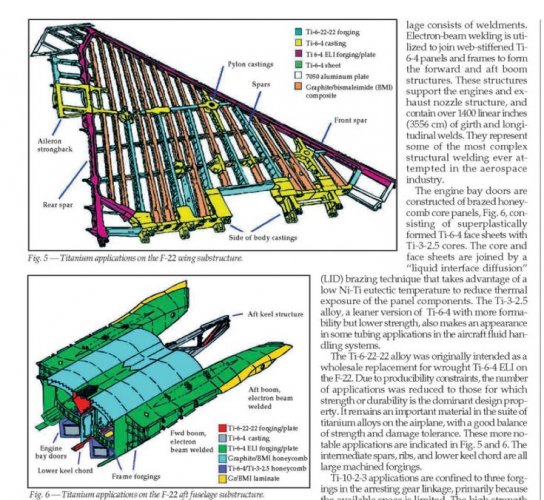
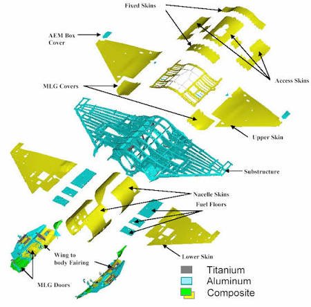
we really don't appreciate the amount of composites used in KAAN enough.
It’s mostly skin, though. Beneath it, there’s a significant amount of titanium (i.e., the bulkheads) and aluminum alloys.

In the case of the F-22, this is how it is:
Edit: Here's the F-35:
 

Attachments

  • 1000083243.jpg
    1000083243.jpg
    131.8 KB · Views: 308
  • 1000083244.jpg
    1000083244.jpg
    38.5 KB · Views: 313
Last edited by a moderator:
Apparently no actual optics inside the EOTS enclosure (yet).
Yep, there’s still some time for that, but all sensors are scheduled to be integrated this year (and are on track to do so). Even if they weren’t, all of their downrated variants are already being tested on Kızılelma.

============

Is it just me, or have the wing roots gotten thicker?
 

Attachments

  • 1000083253.png
    1000083253.png
    2 MB · Views: 353
Last edited by a moderator:
^ I was thinking the same exact thing just a minute ago. But wasn't sure if its thicker or looks thicker since the intake structure is slightly different now.

In any case, as aviation fans, the progress of Turkish aerospace has been exciting, perhaps as much as China, in terms of how many new updates we keep reading about.

Overall, among NATO countries outside of the US, all these new things popping up from Poland and Turkey (naval, armor, aviation) have been very interesting.
 
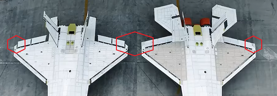
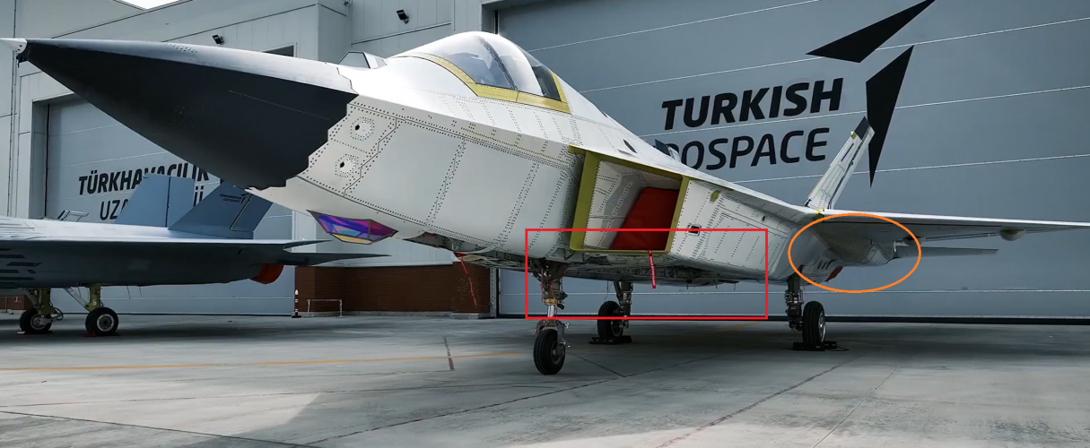
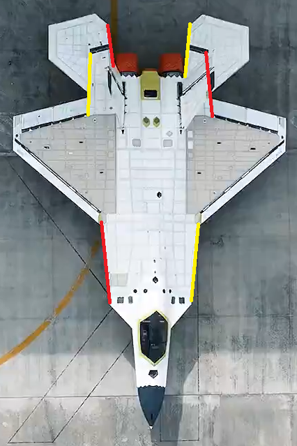
update to edge alignments. Also some new hump aft (orange circle)
Nice summary of the visual changes, although it is not fully complete yet. Such an extensive redesign/evolvement from pre-CDR to post-CDR would have truly been a nightmare fuel for any Western engineer...

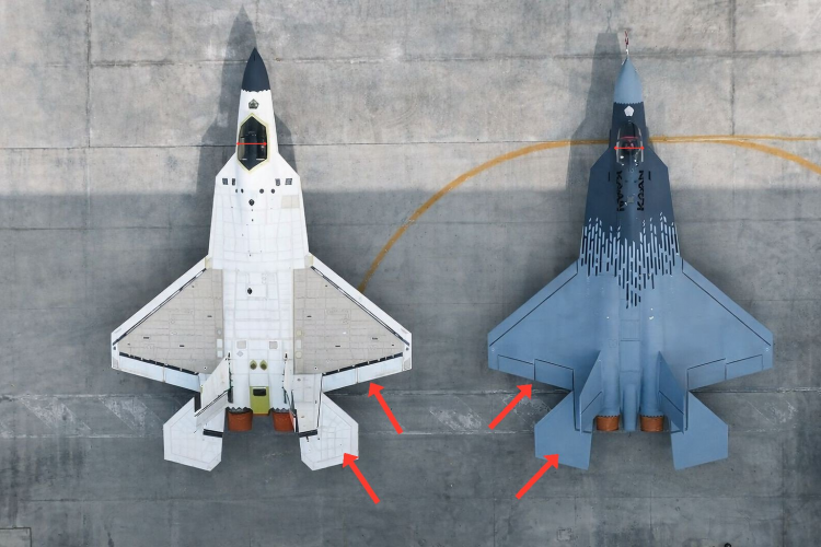
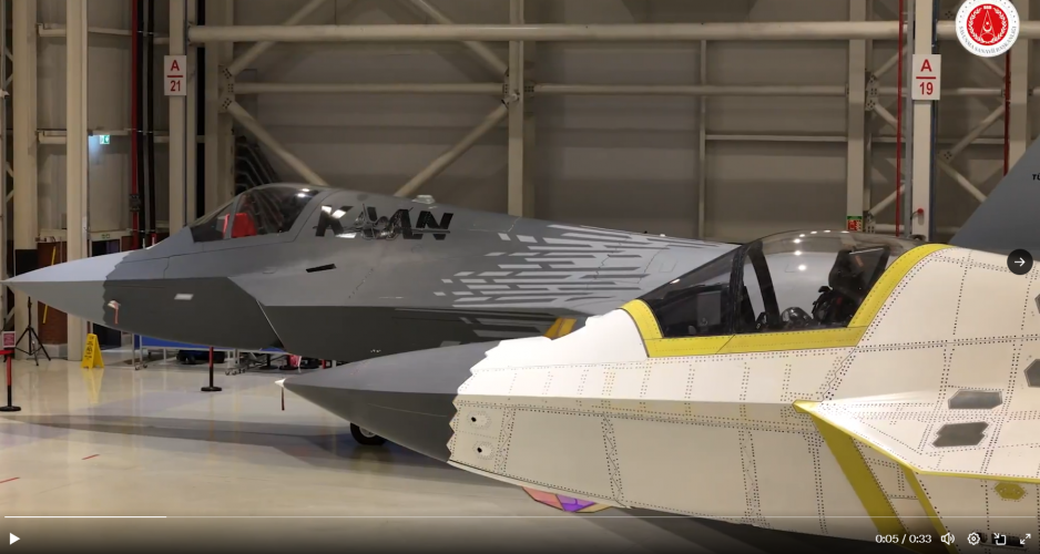
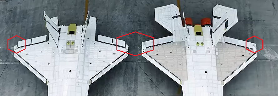
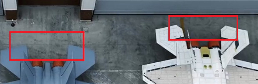
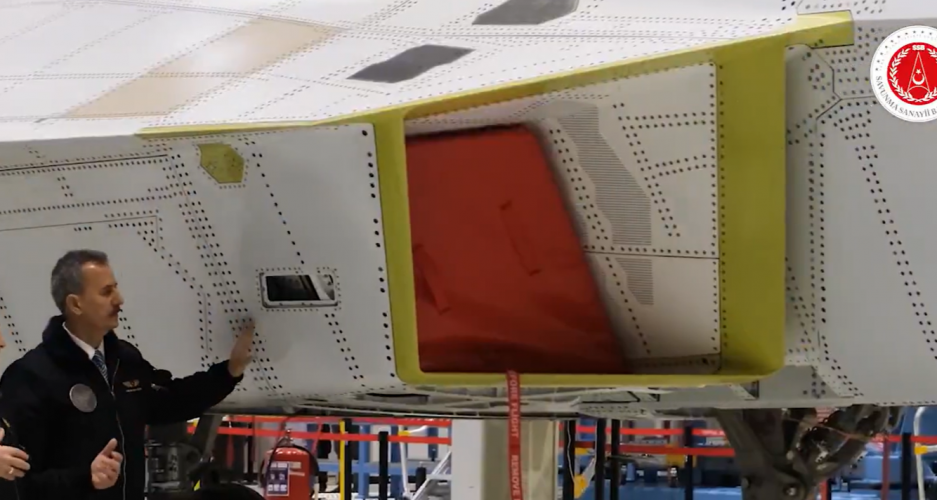
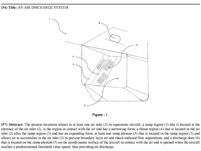
I have attached some of the changes we have noticed below. In addition to those, the main landing gears are now side mounted, and the canopy bar is internal this time. The EOTS has been moved forward, the plate to which the radar is attached has been shifted slightly further forward, and the double chin has been eliminated. Length-wise, the intakes/ducts no longer extend to the canopy, and a boundary layer flow discharge system has been added to replace the old non-stealth spill duct. There are numerous antenna housings for EW, most notably at the front and rear tips of the wings and of the vertical stabilizers (as well as numerous conformal datalink antennas on the front and aft central fuselages). The tail boom has also been redesigned. The wings are now wider, and the ailerons and flaps are the same size. While the P0 had no IWBs, the P1 features not only side bays but also side-by-side belly bays.

The aft hump is also present on the P0, but on the P1 it extends further to the wing root and is slightly larger:

We might be are onto something...

IMG-TAI-TFX (1).jpg

Good catch on the edge alignment, that critical detail somehow slipped past all of us.
 

Attachments

  • 1000083636.png
    1000083636.png
    618.8 KB · Views: 96
  • 1000083635.png
    1000083635.png
    510.8 KB · Views: 90
  • 1000083634.png
    1000083634.png
    353 KB · Views: 84
  • 1000083633.png
    1000083633.png
    347.4 KB · Views: 79
  • 1000083632.png
    1000083632.png
    308.5 KB · Views: 82
  • 1000083638.png
    1000083638.png
    576.2 KB · Views: 318
  • 1000083631.png
    1000083631.png
    167.6 KB · Views: 100
Last edited:
Exactly. P0/GTU-0 (Designated as: Development Test Unit-0) was precisely that – an engineering unit built to physically validate whether theoretical calculations and designs could be translated into functional hardware.

As you noted, the design shown on the slide corresponds exactly to the P0 configuration.
It is somewhat surprising that the P0, which was originally intended as merely a ground prototype provided so much valuable information after just two test flights, especially for stability and control.

But I think the real -and hidden- "hero" here is the digital twin. The MMU program employs extensive use of digital twin, PLM, CAE etc at virtually every aspect of the design and development phases. During our conversation, the chief test pilot told that he was happily surprised to see that much overlap with the simulated data of the digital twin and those gathered from test flights at certain aspects.
 
It is somewhat surprising that the P0, which was originally intended as merely a ground prototype provided so much valuable information after just two test flights, especially for stability and control.

But I think the real -and hidden- "hero" here is the digital twin. The MMU program employs extensive use of digital twin, PLM, CAE etc at virtually every aspect of the design and development phases. During our conversation, the chief test pilot told that he was happily surprised to see that much overlap with the simulated data of the digital twin and those gathered from test flights at certain aspects.
Holy shit orko_8 himself is still among us!

1000083663.gif


A new episode with @hepdurgunsu covering the new prototype reveal would be much appreciated!
 
Last edited:
Nice summary of the visual changes, although it is not fully complete yet. Such an extensive redesign/evolvement from pre-CDR to post-CDR would have truly been a nightmare fuel for any Western engineer...
Did you mean there will be further changes still in subsequent unit?
 
Did you mean there will be further changes still in subsequent unit?
Nope, just that there are so many design changes from P0/GTU-0 that there's much more than just edge alignments or an aft hump to discuss...

In addition to those, the main landing gears are now side mounted, and the canopy bar is internal this time. The EOTS has been moved forward, the plate to which the radar is attached has been shifted slightly further forward, and the double chin has been eliminated. Length-wise, the intakes/ducts no longer extend to the canopy, and a boundary layer flow discharge system has been added to replace the old non-stealth spill duct. There are numerous antenna housings for EW, most notably at the front and rear tips of the wings and of the vertical stabilizers (as well as numerous conformal datalink antennas on the front and aft central fuselages). The tail boom has also been redesigned. The wings are now wider, and the ailerons and flaps are the same size. While the P0 had no IWBs, the P1 features not only side bays but also side-by-side belly bays.

The aft hump is also present on the P0, but on the P1 it extends further to the wing root and is slightly larger:
 
Last edited:
Does this seam line mean that the radome is made of several pieces? If so, does it matter in terms of performance or observability? I saw an article from chinese forum arguing that the seam deteriorates the effect of sawtooth outline of the radome
 

Attachments

  • 1000022595.jpg
    1000022595.jpg
    316.7 KB · Views: 247
Last edited by a moderator:
View attachment 804443

Does this seam line mean that the radome is made of several pieces? If so, does it matter in terms of performance or observability? I saw an article from chinese forum arguing that the seam deteriorates the effect of sawtooth outline of the radome


The radome will be replaced when it’s time to test the FCR.
 

Attachments

  • 1000084717.jpg
    1000084717.jpg
    71.5 KB · Views: 244
Last edited by a moderator:
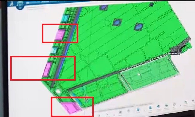
1772964875020.png
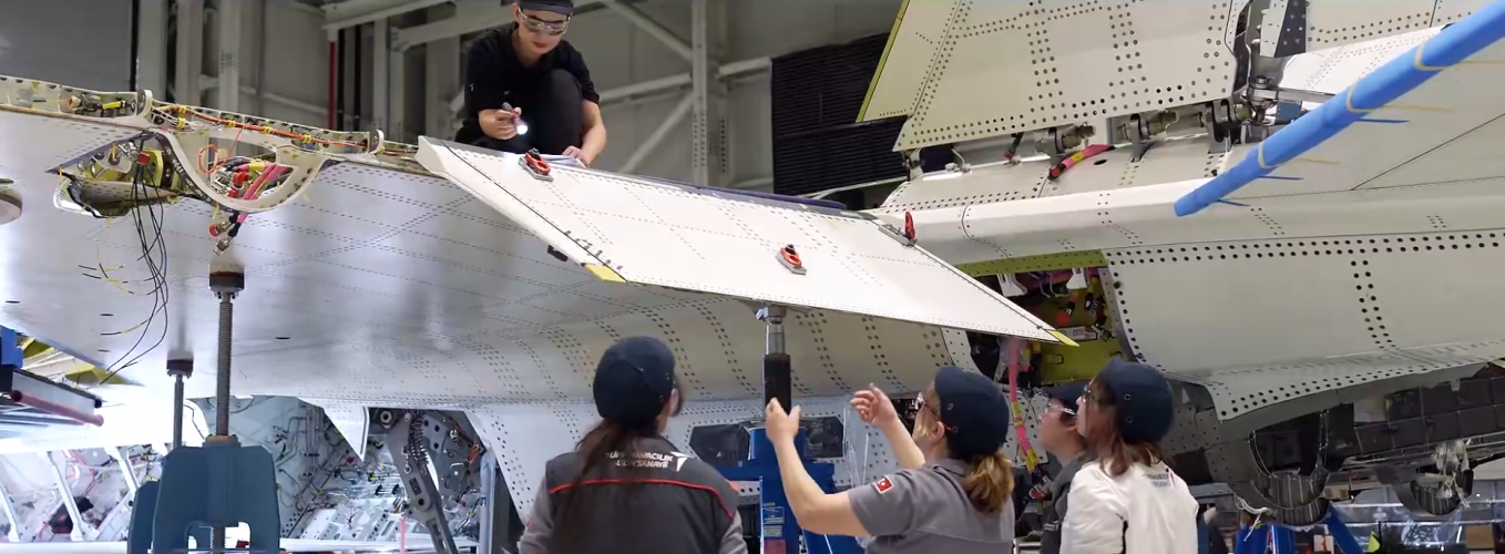
The purple (and blue) areas should house sensors.

View of landing-gear bay and sideweapons bay which still has structural components.
 
Last edited:
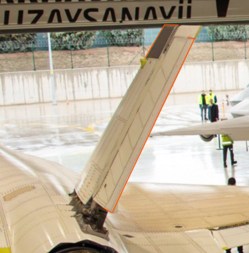
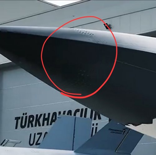
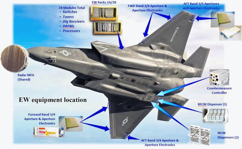
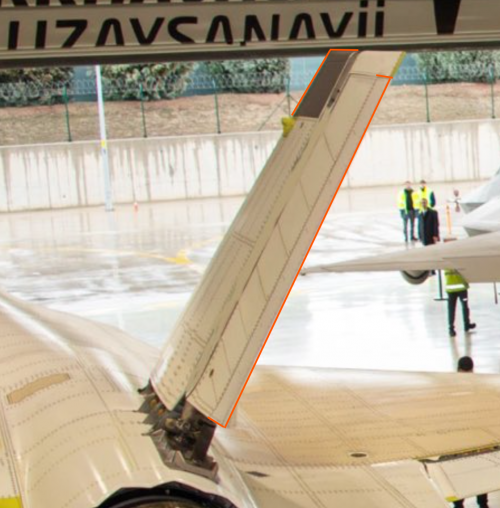
The leading-edge sensor housings look quite interesting. Any insight into what they contain? We've been guesstimating that the trailing-edge wingtips, along with the leading-edge tips of the vertical stabilizers, are likely associated with EW systems.

1000084872.jpg

Could it be that the leading edge housings accommodate some sort of N036L-equivalent arrays like the Su-57?

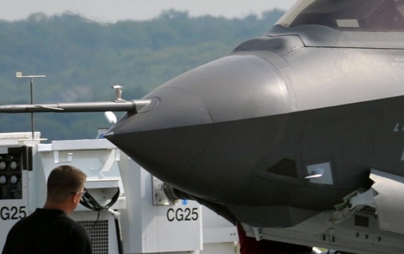
Edit: Nope, they're clearly for an AN/ASQ-239 equivalent, given the similar placement on the F-35.


I'm a sucker for towed decoys, I just wish they'd developed one for the Kaan :(
 

Attachments

  • 1000084875.png
    1000084875.png
    353 KB · Views: 96
  • 1000084876.png
    1000084876.png
    347.4 KB · Views: 90
Last edited:
The leading-edge sensor housings look quite interesting. Any insight into what they contain? We've been guesstimating that the trailing-edge wingtips, along with the leading-edge tips of the vertical stabilizers, are likely associated with EW systems.

View attachment 804692

Could it be that the leading edge housings accommodate some sort of N036L-equivalent arrays like the Su-57?

Edit: Nope, they're clearly for an AN/ASQ-239 equivalent, given the similar placement on the F-35.


I'm a sucker for towed decoys, I just wish they'd developed one for the Kaan :(
There will be a towed decoy
 

Similar threads

Back
Top Bottom