Phazotron Sapfir-23 and Sapfir-25 radar

I just checked the Marmain / Belyakov book and it doesn't say anything about the export version's radar in the Russian, French or English editions.

The recent MiG Flying Through Time book is similarly unhelpful.

Yefim Gordon specifically says the export MiG-25PD had the Smerch-A2 radar as does Piotr Butowski in various older publications.
 
Last edited:
Thanks for looking, well we just have solid proof of the iraqi PDs having the Sapfir-25, so we should go with that rather than old, likely mistaken info. Cooper kept saying the same about the Smerch being in export PDs. You'd think with a drastic change such as a completely different radar the soviets would give them different designations, which of course it's not the case, we just have PD and PDS.

Incidentally, these export PDs are actually better equipped than soviet ones, they have the SPO-15 and KDS-155 which the soviet ones never received.
 
I just checked the Marmain / Belyakov book and it doesn't say anything about the export version's radar in the Russian, French or English editions.

The recent MiG Flying Through Time book is similarly unhelpful.

Yefim Gordon specifically says the export MiG-25PD had the Smerch-A2 radar as does Piotr Butowski in various older publications.
Hello,
As lancer21 said, all export PDs and PDS got the N005 radar (including those for Syria). It was not a big deal for the Soviets at the time since they already were receiving MiG-31s with N007 Zazlon.
lancer is also right about the presence of newer RWR equipment and countermeasures that the Soviet ones lacked.
 
Does anyone happen to know the material that was used in the windows on the faceted TP-23 IRST? I just can't seem to find an answer, anywhere.

Sorry.
 
I just checked the Marmain / Belyakov book and it doesn't say anything about the export version's radar in the Russian, French or English editions.

The recent MiG Flying Through Time book is similarly unhelpful.

Yefim Gordon specifically says the export MiG-25PD had the Smerch-A2 radar as does Piotr Butowski in various older publications.

Yes,all exported MiG-25PDE had in fact RP-25E 'Smerch-A2E' only LPRF pulse radars with max output pulse power of 600kW.

Max detection distance was 120km ,max height of detected/tracked aircraft was 30km.

RP-25 Smerch-A.png
 
Yes,all exported MiG-25PDE had in fact RP-25E 'Smerch-A2E' only LPRF pulse radars with max output pulse power of 600kW.

Max detection distance was 120km ,max height of detected/tracked aircraft was 30km.

View attachment 781279
We know this is incorrect for Iraqi MiG-25PD at least because we have the manual describing the radar as Sapfir-25.
 
We know this is incorrect for Iraqi MiG-25PD at least because we have the manual describing the radar as Sapfir-25.

I wrote details about PDE version but IrAF also received PDS/PDSG from 1983.Some of earlier bought PDE was modernised to the version PDSG level . That version had N005E 'Sapfir-25E' pulse Doppler radar.
 
Did you read the manual?

It explicitly is for MiG-25PD and describes it as fitted with Sapfir-25 radar. It also says the same manual can serve for MiG-25PDS and no differences are noted in the manual between the MIG-25PD and MiG-25PDS. No export suffixes are in evidence.

AFAIK the English manual version was for Iraq, so it strongly suggests Iraq got MiG-25PD (new build?) with Sapfir-25 and then additionally some MiG-25PDS (rebuilds) also with Sapfir-25. Unless their MIG-25PD were upgraded from Smerch-A2 to Sapfir-25 without becoming MiG-25PDS.

Other export customers might have got Smerch-A2?
 
Last edited:
Did you read the manual?

It explicitly is for MiG-25PD and describes it as fitted with Sapfir-25 radar. It also says the same manual can serve for MiG-25PDS and no differences are noted in the manual between the MIG-25PD and MiG-25PDS. No export suffixes are in evidence.

AFAIK the English manual version was for Iraq, so it strongly suggests Iraq got MiG-25PD (new build?) with Sapfir-25 and then additionally some MiG-25PDS (rebuilds) also with Sapfir-25. Unless their MIG-25PD were upgraded from Smerch-A2 to Sapfir-25 without becoming MiG-25PDS.

Other export customers might have got Smerch-A2?

Of course I did ( source was MCM ):

https://www.mycity-military.com/Avioni/MIG-25-Foxbat_147.html#p2610692
As I wrote ,IrAF first received 12 MiG-25PDE with LPRF pulse radar RP-25E 'Smerch-A2E' from 1979.They were in the 97th fighter sqn. From 1983 they had another fighter sqn but with PDS/PDSG with N005E 'Sapfir-25E' pulse Doppler radar ,it was 96th FS (10 pcs). In the meantime,12 PDE's from 97th FS were modernised to PDS/PDSG level ( PDSG had SPS-161E Geran-E/ Izd L101E , active jammer station).

Note: there was no real PD in the IrAF,only export version PDE.

All 22 PDE/PDS/PDSG could carry only R-40RD1/TD1 as export versions of R-40RD/TD.
 
(notes marked with numbers in brackets)

Just for clarification. All radars used in Mig-25 (at least in serial production) were LPRF, both Smierch and Saphir.
And even if Saphir - had some Doppler modes to look though ground clutter (but rather not "look down, shoot down", rather "slant look" ), even those "Doppler modes" were still, in my opinion*(1), LPRF.

Low PRF - by definition that distance measurement is unambiguous. In most "non Doppler" modes Sapfir - is just classical LPRF - with no doubts.
For "Doppler modes" , well: This design still, according to my knowledge, uses magnetron**(2) for main signal generation.

So emitted pulses have random phases -they are not coherent. To achieve coherence "on receive"
(see also https://www.radartutorial.eu/08.transmitters/Pseudo-coherent Radar.en.html )
, one approach would be to use internal coherent generator (COHO) - as reference signal (internal coherence).

In such setup - received phase of echo from each emitted pulse is somehow corrected - to align with reference, coherent signal.
How could be this accomplish technically? when pulse is emitted - there is measured its phase with reference to COHO signal.
Then on receive - this difference is added in some kind of "phase shiftier"***(3) placed somewhere in receiving path.
As a result - echos after this "phase shiftied signals", are coherent - and they can be processed using well known Doppler processing. This measured phase is changed from pulse to pulse, as each emitted pulse has random phase and need to be corrected separately, and phase correction can be applied only to the last emitted pulse****(4). In other words - Doppler processing can be applied to the first unambiguous distance. (So by definition - this is still LPRF).


Some other speculations:
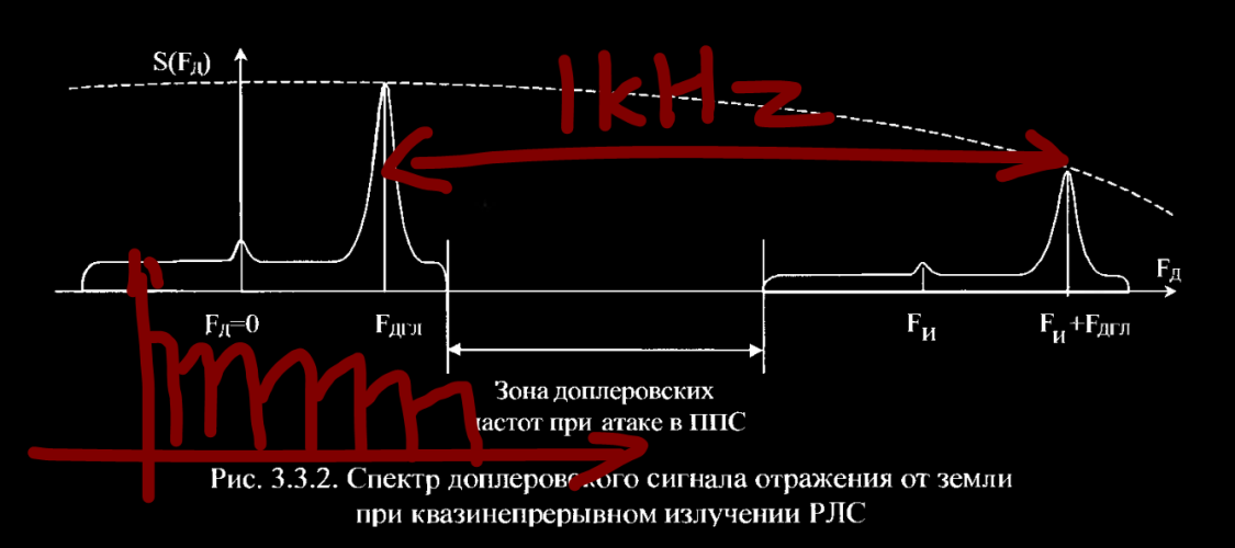
Unambiguous range is of course (1/2)*c*T = (1/2) * c * (1/PRF). So for example: when PRF is 1kHz - distance is 150km.

On the other hand - i "Frequency/Doppler space" - in coherent systems, unambiguous frequency is 1/PRF. So for example PRF=1kHz - all frequencies repeats with such frequency. They are "wrapped" into that frequency interval.
It is simple not possible to recognize the real Doppler frequency (maybe only by changing PRF in consecutive pulse bursts).
Moreover - there is folded everything to such limited frequency range:
- ground returns (whose are not strictly "0Hz" but tooks some space - depending on antenna beam width and scanning angle in respect to direction of flight. Actually this alone may cover the whole 1kHz window ...*****(5)
- slow moving ground objects (for example cars etc) ******(6)
- "real" targets

All in all 1kHz PRF is completely useless from Doppler processing point of view...
So what can be done? Of course an option is to increase PRF, to , let say 4kHz or even better to 8kHz. In 4kHz setup - ground returns will take >1kHz so there is still <3kHz for all other returns, so chance that target will be covered by ground returns is >~25%, not so bad... and in case of PRF=8kHz - is even better.
But 4kHz provides unambiguous range only 37km and 8kHz just 18,7km.
So, in case of 8kHz - if we observe return "on oscilloscope" from distance 10km we just do not know if it is from the first range 10km or the second range: 28.7km.
If we have - truly Doppler radar ( "on send and receive") - when all emitted/received pulses are coherent, it does not matter so much: we still does not know real distance and real closing speed (they are both "wrapped"), but returns from all distances are coherent - and may be processed with Doppler processing.
And the real values of distance and closure speed can be resolved later by changing PRF in consecutive pulse bursts.
And the PRF might be further increased above this 4 or 8kHz , depending on needs or radar design
But here we just land in Medium PRF, and radars like APG-66, PS-46/A (Viggen).... and so on..

But in case Saphire - it is not possible... it can correctly process only the last pulse****(4), so it can process the single, the closest range using Doppler filters.
Echos from the second range (from last but one emitted pulse) - are received but each of them is corrected using information about the phase of the last pulse. So effectively - all pulses from second range have random phases... so they are in frequency space nothing more than broad band noise, including also strong returns from ground..
That, for sure, does not help in any case. Even if we want only process "coherent targets" from the first window..******(6)
(See https://www.radartutorial.eu/08.transmitters/Pseudo-coherent Radar.en.html - the last sentence)

Also - increase of PRF, to solve narrow window in frequency space, can not be done freely, as this limits instrumental range (to the first unambiguous range).
In case of Saphire pulse -Doppler modes cited range is somehow 15km , 24km , or even 28km.
So this results in PRF in range from somehow, let say above 4kHz and below 9kHz.
All in all - still somehow useful.
In "Doppler weather modes" instrumental range can be selected manually to somehow longer ranges - the longer range decreases probability of detection - there is higher change that target will be in blind frequency. But pilot has some trade-off. to manually select range.

In case of Mig23/25 - there is not used internal "coherent" oscillator, but as coherent reference are taken signals from ground returns, taken by sidelobes ("external coherence"). Thus Doppler modes works only if such ground return from side-lobe is present. Thus plane have to fly not higher than 500m above ground and radar beam is pointer somehow ~1bar down (thus it is not possible to fly high and look down, so I called this "slant down radar", with vertical 1 bar scan pattern, limited to somehow in azimuth to +/-30 deg respect to axis of plane. (greater angles increases blind areas in LPRF frequencies - as mentioned above - so for that reason are forbidden.)
And for "meteo" Doppler modes (to filter returns from radio -reflective clouds, or chaffs) - there are no limitations of flight altitude or scan limits... but there is curiosity - that - to detect target - it has to fly trough that reflective environment...
So if there are two targets - one in such radio-reflective cloud and second not... in this mode the second will be (might be?) not detected - as there is no interference to be source of Doppler reference signal ... and in manual .. this mode is rather advised to be used only when necessary..

Notes:
*(1) If somebody has better understanding/knowledge I am curious to get familiar with them
**(2) some sources claims that, at least since ML variant, there are two Klystrons - one for low power continuous harmonic signal for missile illumination, - and that is understandable.
the second ... for normal radar work. Well I am not sure about the second - if this really klystron or just magnetron. Normal radar work of LPRF radars requires high power emitted pulse, and this is easily provided by magnetrons. And using klystron (actually they are for sure used as main emitter since Mig-29,31, Su-27), allows to control emitted pulse, and to achieve fully coherent radar "on emit" .
And in Mig-23/25 - this is not the case, as they required "external coherence". But maybe there is used Klystron (without fully coherent input signal), and that allows to have more "clean" pulse without somehow intra-pulse defects , with more stable frequency, but still not fully coherent (?) Better emitted signal might improve Doppler processing on receive, as only phase need to be corrected...
Somehow similar case is observed in evolution of Cyrano IV into RDM radar - they also replaced magnetron by klystron. But that design still is LPRF and has severely limited look down - shoot down capability. So maybe it is more difficult to create fully coherent radar (this coherent oscillator, and all backends) than to use Klystron? But Klystron still may provide some benefits, in terms of signal purity? Even if not fully coherent ? Or maybe RDM is fully coherent radar, but for some reasons, only LPRF?


***(3) actually - this in side of receiving path, not like in PESA radars :), and even simpler, when signal is converted to digital form, but idea is the same...correct phases of received signals.. to make them coherent in receive path

****(4) as far as I remember , in mig-25 manual, there is switch - to select detection range: closer from 0 to let say 15km (I write from memory) and further (let say from 14 ... 28 km...) .. so maybe still it is possible to process the second range window? in such case, there will be memorize phase of signal , and it would be used to correct not the echo from last pulse , but one before last... maybe this is still possible, but I do not know how to be implemented "with external coherence"

*****(5) (for let say taking some extreme case : antenna beam 3.5 deg , set to 45 degree with plane speed 300m/s , f=10GHz according to my calculations - difference in ground speeds in respect to plane on "sides" of the beam is ~13m/s - as is shown bellow - this is almost 1kHz

******(6) ground moving objects (cars etc) - those have low speed (for example for radar frequency f =10GHz , and car speed 50km/h - 50km/h/3.6 -> ~14m/s -> 2*v/c* f -> (~30m/s / 3* 10^8 m/s )* 10^10Hz = ~10^3 = 1kHz.

*******(7) Good side is - that echo from the second (and also following) range interval(s) will influence only corresponding range bin in the first "coherent" internal. So taking in account the above mentioned example 8kHz and with first range: 0..18.5km ... echo (either ground clutter or something else) from distance 28.5 km will impact only to range cell placed in 10km. And as range cells are rather narrow - corresponds to pulse length that is in case of Saphir - let say 4microseconds (I do not know what is pulsewith in PD mode..)- thus only from area 1200m .. and signals from long range will be still weaker .. and smash over the whole frequency range, whereas echo from first "coherent" range - will be rather sharp(er).. this might not prevent detection in many cases...
But this still is some "background noise" that decrease sensitivity, at least comparing with true PD radars..

 
1. When the MV radar mode has been selected, the returned signal is further processed in the Pulse-doppler channel of the Sapfir-23E. At first the signal is led to the linear receiver, where it is amplified and sorted out by the amplitude detector. Then it is routed to the 49 multi-channels Doppler filter (a comb filter), where the selection of moving target takes place.
Do you have similar material, describing technical details about N003/004/006/008/008E or Sapfir-23ML/ML-2/MLA/MLA-2/MLAE-2? I was searching about soviet radars, which can be divided, specific for S-23 series, divided into two generations:
| 1.S-23D-III series
| 2.S-23ML series

The performance and weight is of drastic difference, so I suppose there should be some big advance within. From historical description, the evolution is:
| S-23D(the ) -> S-23ML-> RP-29/N019.
From technical materials, we could find that:
| 1. S-23D(S-23E) uses comb filter, which suggest that it is a semi/quasi-coherent radar, utilize doppler effect of signal but not integrate them on different frequencies. (From this quote)
| 2. N019 is strictly a pulse-doppler radar. It enables range gate, frequency searching, implement digital (data) processors, 3 HPRF for look-down, etc. (From 'Бортовой комплекс самолетовождения, прицеливания и управления самолетом МиГ-29Б', I don't understand russian so there might be mistakes)

So, the question is, since there is a great technical difference between S-23D and N019, as the medius terminus, which step should we put S-23ML at? (What is needed is technical descriptions, such 'it uses doppler-filter arrays' or 'it integrates the signal'.)
I will be grateful if you could finding the answer and definitely set an attribution in my note.
 
S-23ML changed two major things compared to S-23D-III.

The antenna type changed from inverse-cassegrain to twist-cassegrain.
The electronics were changed for more advanced, lighter-weight solid state electroni

I don't think the basic underlying principles changed, it was still using Low PRF, magnetron transmitters, external coherence.
 
Last edited:
So the N008 block list gives some possible idea of the scope of the changes.

  1. Block N008-01 - antenna
  2. Block N008-42 - distributor heterodyne signal
  3. Block S23ML-74А - block of imitation and target control
  4. Block S23ML-12B - transmitter KNP [CW]
  5. Block S23ML-02A - transmitter impulse [Pulse]
  6. Block S23-37 - high-voltage indication rectifier
  7. Block S23ML-65 - block automatic brightness control
  8. Block S23-75 - control panel brightness
  9. Block S23-05 - indicator
  10. Block S23ML-64 - control unit control
  11. Block S23-50 - antenna feeder kit devices
  12. Block N008-89А - high-frequency receiver
  13. Block N008-40 - mounting kit
  14. Block S23-15 - scanner
  15. ASP (aviation rifle sight, not included in N008E)
  16. Block S23ML-44 - control panel middle
  17. Block S23ML-24 - control panel left
  18. Container radioelectronic blocks N008-10
  19. Block N008-94 - switching unit
  20. Block N003-17 - power supply unit
  21. Block N003-27 - power supply unit AVM
  22. Block N003-54 - interface block with KZA (control and recording equipment)
  23. Block N008-30 - distribution power box
  24. Block N008-61E - target designation unit
  25. Block S23-67 - thermal control unit
  26. Block S23-57 - current stabilizer indicator
  27. Block N008-34 - control panel right

Some observations:

S-23ML introduced new pulse and CW transmitters which didn't get upgraded again even in N008.
Almost no original parts remain unchanged in N008.
 
Last edited:
So the N008 block list gives some possible idea of the scope of the changes.

  1. Block N008-01 - antenna
  2. Block N008-42 - distributor heterodyne signal
  3. Block S23ML-74А - block of imitation and target control
  4. Block S23ML-12B - transmitter KNP [CW]
  5. Block S23ML-02A - transmitter impulse [Pulse]
  6. Block S23-37 - high-voltage indication rectifier
  7. Block S23ML-65 - block automatic brightness control
  8. Block S23-75 - control panel brightness
  9. Block S23-05 - indicator
  10. Block S23ML-64 - control unit control
  11. Block S23-50 - antenna feeder kit devices
  12. Block N008-89А - high-frequency receiver
  13. Block N008-40 - mounting kit
  14. Block S23-15 - scanner
  15. ASP (aviation rifle sight, not included in N008E)
  16. Block S23ML-44 - control panel middle
  17. Block S23ML-24 - control panel left
  18. Container radioelectronic blocks N008-10
  19. Block N008-94 - switching unit
  20. Block N003-17 - power supply unit
  21. Block N003-27 - power supply unit AVM
  22. Block N003-54 - interface block with KZA (control and recording equipment)
  23. Block N008-30 - distribution power box
  24. Block N008-61E - target designation unit
  25. Block S23-67 - thermal control unit
  26. Block S23-57 - current stabilizer indicator
  27. Block N008-34 - control panel right

Some observations:

S-23ML introduced new pulse and CW transmitters which didn't get upgraded again even in N008.
Almost no original parts remain unchanged in N008.
Thanks! :) o7
 
So the N008 block list gives some possible idea of the scope of the changes...
Um, any other sources? This one is interesting but not enough.((
Sorry troubling you again.))

(S-23ML introduced two kind of transmitter - this might suggest that it introduced more advanced pulse modulation method comparing to S-23D.)

edit: Nope, S-23E has 2 transmitters too.
 
Last edited:
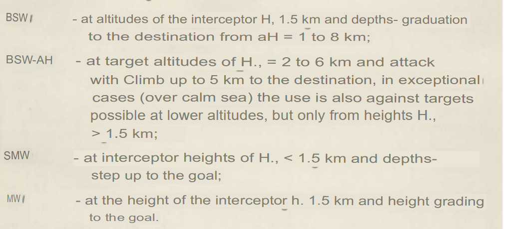
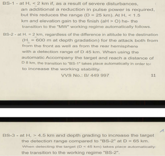
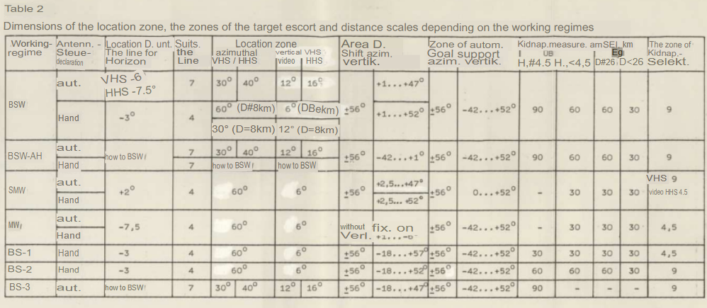
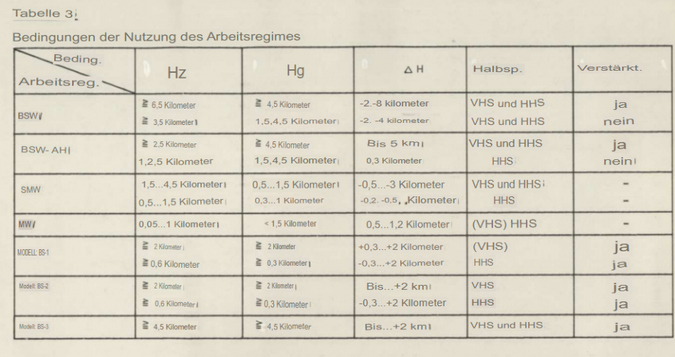
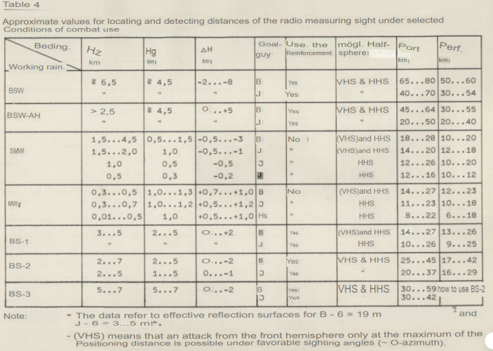
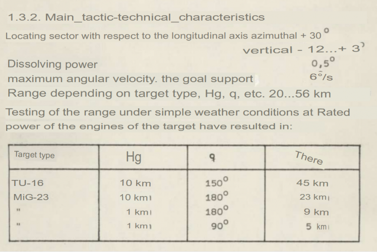
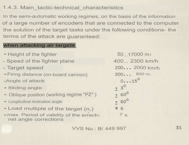
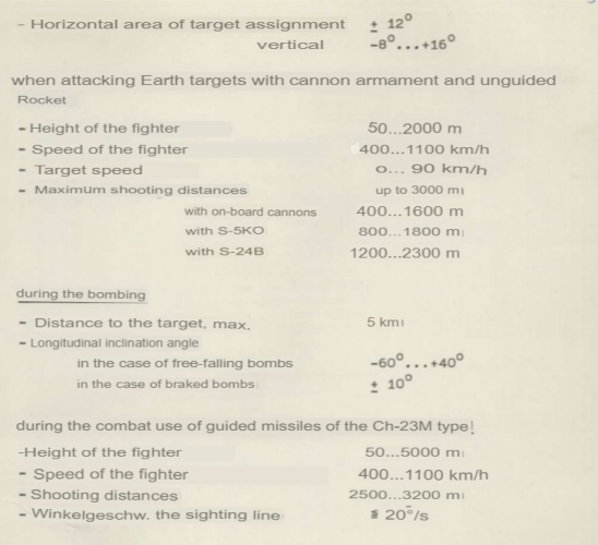
Here is a quick overview of SAPHIRE-23MLA. As you guys can see, ranges are greatly reduced when using BS filter. HJ is predator height and HZ is prey height. I also attatched an image of irst + radar technical characteristics. Also an image of when radar is able to be used. Also an image of radar features and how they work.
 

Attachments

  • 1763514030743.png
    1763514030743.png
    156.8 KB · Views: 62
  • 1763514189452.png
    1763514189452.png
    210.9 KB · Views: 65
  • 1763514205595.png
    1763514205595.png
    357 KB · Views: 74
  • 1763514219294.png
    1763514219294.png
    341.5 KB · Views: 65
  • 1763514231559.png
    1763514231559.png
    501.1 KB · Views: 60
  • 1763514252207.png
    1763514252207.png
    245.6 KB · Views: 60
  • 1763514270973.png
    1763514270973.png
    218 KB · Views: 53
  • 1763514285921.png
    1763514285921.png
    214.4 KB · Views: 54
Last edited:
https://web.archive.org/web/20140416182631/https://istokmw.ru/uploads/files/static/61/UHF2009-1.pdf
This file (page 19) described the development of a 4 frequency transmitter based on klystrons, might linked to the 'ЛИТЕР' frequency of R-23/24 guidance. Besides, this file could confirm that the look-down mode utilize the same transmitter as illumination.

p.s. All the description I found on internet talking about 'delta-H' 'BSV' etc. modes only mention parameter PRF=1kHz in the look-up modes. I still cannot confirm which and what kind of PRF is used in look-down modes. It can't be 1kHz anyway.
If Ahmad's claim about 100kHz using in illumination is true, which might not be true, then there's no reason not considering S-23 systems using HPRF, or at least with switchable PRFs. (Still valid even if Ahmad's claim is not true.)

If anyone can provide more concrete proof about the usage of 100kHz PRF, no matter the mode, I will appreciate it.
 
https://web.archive.org/web/20140416182631/https://istokmw.ru/uploads/files/static/61/UHF2009-1.pdf
This file (page 19) described the development of a 4 frequency transmitter based on klystrons, might linked to the 'ЛИТЕР' frequency of R-23/24 guidance. Besides, this file could confirm that the look-down mode utilize the same transmitter as illumination.

p.s. All the description I found on internet talking about 'delta-H' 'BSV' etc. modes only mention parameter PRF=1kHz in the look-up modes. I still cannot confirm which and what kind of PRF is used in look-down modes. It can't be 1kHz anyway.
If Ahmad's claim about 100kHz using in illumination is true, which might not be true, then there's no reason not considering S-23 systems using HPRF, or at least with switchable PRFs. (Still valid even if Ahmad's claim is not true.)

If anyone can provide more concrete proof about the usage of 100kHz PRF, no matter the mode, I will appreciate it.

Hm, I've never heard or read before that look down or look up can be the the mode . That is only the capability of one radar, am I right ?
 
Hm, I've never heard or read before that look down or look up can be the the mode . That is only the capability of one radar, am I right ?
That ability relate to signals, which is different between the modes. For example, one use MPRF for scanning higher, while use HPRF for scanning lower. *Maybe this example is N019, I don't exactly remember it.
Anyway there's 2 transmitters on S-23, relatively used in scanning higher and lower. higher - S-23 works like a pulse radar. Lower - MTI.
 
https://web.archive.org/web/20140416182631/https://istokmw.ru/uploads/files/static/61/UHF2009-1.pdf
This file (page 19) described the development of a 4 frequency transmitter based on klystrons, might linked to the 'ЛИТЕР' frequency of R-23/24 guidance. Besides, this file could confirm that the look-down mode utilize the same transmitter as illumination.

p.s. All the description I found on internet talking about 'delta-H' 'BSV' etc. modes only mention parameter PRF=1kHz in the look-up modes. I still cannot confirm which and what kind of PRF is used in look-down modes. It can't be 1kHz anyway.
If Ahmad's claim about 100kHz using in illumination is true, which might not be true, then there's no reason not considering S-23 systems using HPRF, or at least with switchable PRFs. (Still valid even if Ahmad's claim is not true.)

If anyone can provide more concrete proof about the usage of 100kHz PRF, no matter the mode, I will appreciate it.
I have no idea what you are talking about really, and I don't think this document says anything supporting it.

However, this document does give some interesting stuff on Sapfir-23ML.

Besides solid-state, were there other shifts in the company's focus?
Another important, comparable shift in the research institute's focus was the transition to integrated devices. Along with this initial transformation, he laid the foundation for the further diversification of our association's scientific and industrial base
into hardware. The reason for its creation was as follows. Chief Designer Kunyavsky developed a new radar for the MiG-23 aircraft, which for the first time used a chain of master and amplifier klystrons. To solve the main problem facing airborne radar developers—detecting a moving target against the ground—they required pulse-to-pulse frequency stability of hundreds of hertz, which was fundamentally impossible to achieve using magnetron oscillators.

Having solved the problem of detecting a target against the ground using our single-frequency klystron chain, Kunyavsky failed to account for mutual interference between aircraft operating on a single carrier frequency and was dismissed from his post. The question arose of what to do with the promising fighter, the development of which had already cost the country many hundreds of millions of rubles. Minister of the Ministry of Defense V. Kalmykov and Air Force Commander-in-Chief Marshal Kutakhov convened an emergency meeting to discuss the future of the MiG-23's electronic warfare system, which, as usual, included NPO Istok.

S. V. Korolev, in my opinion our company's most outstanding developer, and I repeatedly discussed possible solutions to the current situation and agreed to create an integrated dual-frequency device in the form of a complete microwave transmitter, taking on the bulk of the work of the Ministry of Defense specialists and the full responsibility for achieving the required parameters of the microwave transmitter and, consequently, the radar as a whole. Although the idea had not yet been tested, I presented it at the meeting. Kalmykov, who held our company in high esteem, approved of the idea. Kutakhov also enthusiastically supported it. A decision was immediately made to develop a 4-frequency microwave transmitter for the MiG-23 ML aircraft based on our proposal. Thus was born the "Alternative" monoblock, the first domestically produced integrated device, in whose development and production the radio operators became our component manufacturers. Under the leadership of S.V. Korolev and E.A. Gelvich, the monoblock, which would decide the fate of the MiG-23ML fighter, was quickly created at NPK-2. Perhaps for the first time in the history of electronic warfare development, a fundamental technical solution was implemented by representatives of our research institute.

Below, the evolution of microwave target acquisition principles is examined historically, using specific developments in electronic equipment. The first active use of microwave design principles was in the early 1970s, when developers of airborne radar targeting systems (ARS) were faced with the task of detecting and engaging high-speed, low-observable targets against the ground.

The solution was complicated by the presence of a signal reflected by the ground's surface, the magnitude of which was many orders of magnitude greater than the target's signal. The characteristics of previously developed RASs using transmitters with powerful magnetron microwave oscillators did not allow for the application of the principle of moving target selection due to excessive frequency instability from pulse to pulse. It was necessary to use amplifier circuits with a highly stable, low-power master oscillator, the output stages of which utilized powerful amplifiers such as klystrons or TWTs. NPO Fazotron, the lead organization for the development of the radar complex for the MiG-23 fighter jet, together with specialists from NPP Istok, selected a microwave transmitter built on a three-stage klystron circuit. Through joint efforts, it was possible to fit it within the required dimensions. This three-stage microwave transmitter fully met the technical specifications. Test flights confirmed the effectiveness of the chosen solution in meeting the requirements for the detection and tracking range of targets against the ground.

However, an unaccounted issue arose regarding the radio compatibility of group operations of fighters in a given square.

The klystron-based microwave transmitter emitted a powerful signal on only one carrier frequency, and the planned joint combat operations of a group of four fighters were impossible due to mutual interference when engaging targets against the ground. Placing four amplifier chains with three discrete klystrons and the waveguide equipment connecting them was physically impossible within the given dimensions of the aircraft compartment. Specialists at NPP Istok proposed an innovative solution: leveraging the capabilities of electronic technology, they developed a complex "Alternative" product at NPP Istok. It was a single dual-frequency monoblock consisting of three klystrons and their connecting components, supplied jointly by NPO Fazotron. The proposed miniaturization of the microwave transmitter made it possible to accommodate two "Alternative" monoblocks within the same weight and size parameters of the radar-guided complex and fully meet all the tactical and technical requirements for the MiG-23ML fighter. NPP Istok began serial production of the monoblock in 1975, and by 1980, together with the Generator Plant (Kiev), more than 5,000 units had been delivered for aircraft equipment and operation. Thus, the first integrated microwave technology product (MICROWAVE TECHNOLOGY) was created.
 
That ability relate to signals, which is different between the modes. For example, one use MPRF for scanning higher, while use HPRF for scanning lower. *Maybe this example is N019, I don't exactly remember it.
Anyway there's 2 transmitters on S-23, relatively used in scanning higher and lower. higher - S-23 works like a pulse radar. Lower - MTI.

Thanks, btw , N019 Rubin uses HPRF in the 'Vstrechya' mode ( forward hemisphere) and MPRF in the 'Dogon' mode ( rear hemisphere) .Both working modes, HPRF/MPRF combo can be used in the 'AVT' mode. Only 'V' and 'D' modes can be used with the so called SNP submode for the tracking max 10 differ aircraft in the scan zone.

I've found that combat mode 'MV' of the S-23E (Sapfir-23E) /N003E ( MV is for 'malaya visota' or small altitude) can be in fact ''look down mode' only ..

Citation :

...here is some basic information about the Phazotron Sapfir-23:

(Hs- altitude of the Mig-23, Hc- target altitude)

The N-003E contains of 44 parts weighting total 475kg. Main parts:
Antenna : 56kg
Impulse transmitter: 98kg (klystron type tubes)
KNP transmitter: 48.5kg (providing STT for R-23R)
Parametric amplifier: 8kg
AVM-23 analogue computer : 8.2kg

Radar scan limits in azimuth: ±56º
Radar scan limits in elevation: +52º, -42º
Peak power: 40kW

Basic performance data of the N003E:
The radar detects targets at altitudes from 50 to 25000 m flying at speeds from 500 to 2500km/h.

In real life operations for Mig-23ML/MLA/MF/MLD operating with a Sapfir-23 this feature could be TURNED ON OR OFF
The radar scan modes BSV, BSV-delta H4, BSV-delta H1, SMV, MV are switched automatically according to aircraft altitude Hs (DV-30 barometric probe) and the antenna position ”Delta H” switch. The scan mode BSV-SC can be selected manually by the pilot with the radar mode switch "BSV SC-R-BSMV switched to the BSV-SC position.
e.g. the aircraft is flying with its nose below the horizon (descending), but the antenna bearing is above the horizon. At altitude of 1500m the BSV mode changes to SMV automatically. If the antenna bearing is below the horizon at the same conditions (descend flight), at altitude of 1500m the BSV-deltaH1 mode switches to the MV automatically and vice-versa.
The BSV-SC mode hasn’t altitude limitations, the delta H switch doesn’t have an effect on it.
When the switch NAVED AVT/RUCHN is set to AVT, the radar mode selection is done automatically by the GCI datalink (ARL-SM). The radar scan patterns under GCI are better optimized due to known PPS/ZPS aspect. The one-way commands from GCI are displayed on special symbol indicator mounted on the ASP-23DE gunsight. Pilot can interrupt the GCI datalink anytime setting the switch to RUCHN.

The mode BSV for high/medium altitudes, all-aspect intercepts (Hc<>=Hs), pulse width ~4 µsec, PRF 1Khz, switching altitude Hs>4,5km, Beam width in search 2,5°. Scan patters depend on NAVED AVT/RUCH switch position. Beam width in STT 1.7°.

The modes BSV-delta H4, BSV-delta H1 for high/medium altitudes are useful for searching targets on earth background not using the Doppler shifts (MTI). For all-aspect intercepts, switching altitude is 4.5km>Hs>1,5km. It uses half/third PRF compared to BSV mode. The “differential compensator device” (DKP) filters false ground signals out. For greater search range the parametric amplifier can be switched on. The receiver sensitivity gains of 5-10% (dB/mW).

The modes BS (I BS, II BS, III BS) for high/medium altitudes are used for all-aspect intercepts (Hs<>=Hc) in case of false targets (clouds) and for picking up targets on earth background by using reference coherent signal received by radar side-lobes. The “III BS” mode has the largest search range of 65km, the “I BS” the smallest one of 27km. The most used mode is the “II BS” with 45km search range. The “III BS” mode works only as a search mode. The FFT Doppler filtering techniques are used to select moving targets flying on the earth background. The so-called “blind speeds” are overcome by changing PRF pulses during each scan line. More than 90% of “blind speeds” are covered, what ensures good MTI.

The mode SMV for medium/low altitudes, only rear-aspect intercepts (Hs<Hc), The switching altitude is Hs<1.5km, pulse width ~1 µsec, PRF 1Khz. The scan patters depend on NAVED AVT/RUCH switch position.

The mode MV is used to engage targets flying at low altitudes on the earth background. It is only for rear-aspect intercepts (Hs>Hc), The switching altitude Hs<1.5km, switch “Delta H”<0, pulse width ~1 µsec, Beam width in search 2,5°. The MV mode uses the MTI based on Doppler shifts.

Source: https://forum.warthunder.com/t/remo...ion-for-mig23ml-radar-mode-auto-swap/118921/8

Here we can find more precise data :

''The MV mode is used to engage targets flying lower than the Mig-23 on the earth background. (LD/SD mode) (Hc<Hs). It`s used only for rear-aspect intercepts, pulse width ~1 µsec(search, track), Beam width in search 1,5°. The MV mode uses the „SDC with external coherence“ technique to compare Doppler shifts between the target and earth background. The antenna scan zone is locked in azimuth and elevation.''

Source: https://community.gaijin.net/issues/p/warthunder/i/fkC3NyHwPv3N
 
Last edited:
https://web.archive.org/web/20140416182631/https://istokmw.ru/uploads/files/static/61/UHF2009-1.pdf
This file (page 19) described the development of a 4 frequency transmitter based on klystrons, might linked to the 'ЛИТЕР' frequency of R-23/24 guidance. Besides, this file could confirm that the look-down mode utilize the same transmitter as illumination.

p.s. All the description I found on internet talking about 'delta-H' 'BSV' etc. modes only mention parameter PRF=1kHz in the look-up modes. I still cannot confirm which and what kind of PRF is used in look-down modes. It can't be 1kHz anyway.
If Ahmad's claim about 100kHz using in illumination is true, which might not be true, then there's no reason not considering S-23 systems using HPRF, or at least with switchable PRFs. (Still valid even if Ahmad's claim is not true.)

If anyone can provide more concrete proof about the usage of 100kHz PRF, no matter the mode, I will appreciate it.

PRF of 100kHz ? Hm, I think that all MiG-23/-25 radars are LPRF only with max output pulse power from 40kW to 600kW where PRF is about 1kHz ? On the other side, MiG-29/-31 and Su-27 'FFF' have MPRF/HPRF radars with max output pulse power from 8kW to 10kW ( in HPRF mode) and with PRF in the HPRF mode 180kHz-200kHz ,in the MPRF mode PRF is about 50kHz.
 
Last edited:
PRF of 100kHz ? Hm, I think that all MiG-23/-25 radars are LPRF only with max output pulse power from 40kW to 600kW where PRF is about 1kHz ? On the other side, MiG-29/-31 and Su-27 'FFF' have MPRF/HPRF radars with max output pulse power from 8kW to 10kW ( in HPRF mode) and with PRF in the HPRF mode 180kHz-200kHz ,in the MPRF mode PRF is about 50kHz.
100kHz - See the #44 reply of this post.:)
 
Thanks, btw , N019 Rubin uses HPRF in the 'Vstrechya' mode ( forward hemisphere) and MPRF in the 'Dogon' mode ( rear hemisphere) .Both working modes, HPRF/MPRF combo can be used in the 'AVT' mode. Only 'V' and 'D' modes can be used with the so called SNP submode for the tracking max 10 differ aircraft in the scan zone.

I've found that combat mode 'MV' of the S-23E (Sapfir-23E) /N003E ( MV is for 'malaya visota' or small altitude) can be in fact ''look down mode' only ..

Citation :

...here is some basic information about the Phazotron Sapfir-23:


The N-003E contains of 44 parts weighting total 475kg. Main parts:
Antenna : 56kg
Impulse transmitter: 98kg (klystron type tubes)
KNP transmitter: 48.5kg (providing STT for R-23R)
Parametric amplifier: 8kg
AVM-23 analogue computer : 8.2kg

Radar scan limits in azimuth: ±56º
Radar scan limits in elevation: +52º, -42º
Peak power: 40kW

Basic performance data of the N003E:
The radar detects targets at altitudes from 50 to 25000 m flying at speeds from 500 to 2500km/h.

In real life operations for Mig-23ML/MLA/MF/MLD operating with a Sapfir-23 this feature could be TURNED ON OR OFF
The radar scan modes BSV, BSV-delta H4, BSV-delta H1, SMV, MV are switched automatically according to aircraft altitude Hs (DV-30 barometric probe) and the antenna position ”Delta H” switch. The scan mode BSV-SC can be selected manually by the pilot with the radar mode switch "BSV SC-R-BSMV switched to the BSV-SC position.
e.g. the aircraft is flying with its nose below the horizon (descending), but the antenna bearing is above the horizon. At altitude of 1500m the BSV mode changes to SMV automatically. If the antenna bearing is below the horizon at the same conditions (descend flight), at altitude of 1500m the BSV-deltaH1 mode switches to the MV automatically and vice-versa.
The BSV-SC mode hasn’t altitude limitations, the delta H switch doesn’t have an effect on it.
When the switch NAVED AVT/RUCHN is set to AVT, the radar mode selection is done automatically by the GCI datalink (ARL-SM). The radar scan patterns under GCI are better optimized due to known PPS/ZPS aspect. The one-way commands from GCI are displayed on special symbol indicator mounted on the ASP-23DE gunsight. Pilot can interrupt the GCI datalink anytime setting the switch to RUCHN.

The mode BSV for high/medium altitudes, all-aspect intercepts (Hc<>=Hs), pulse width ~4 µsec, PRF 1Khz, switching altitude Hs>4,5km, Beam width in search 2,5°. Scan patters depend on NAVED AVT/RUCH switch position. Beam width in STT 1.7°.

The modes BSV-delta H4, BSV-delta H1 for high/medium altitudes are useful for searching targets on earth background not using the Doppler shifts (MTI). For all-aspect intercepts, switching altitude is 4.5km>Hs>1,5km. It uses half/third PRF compared to BSV mode. The “differential compensator device” (DKP) filters false ground signals out. For greater search range the parametric amplifier can be switched on. The receiver sensitivity gains of 5-10% (dB/mW).

The modes BS (I BS, II BS, III BS) for high/medium altitudes are used for all-aspect intercepts (Hs<>=Hc) in case of false targets (clouds) and for picking up targets on earth background by using reference coherent signal received by radar side-lobes. The “III BS” mode has the largest search range of 65km, the “I BS” the smallest one of 27km. The most used mode is the “II BS” with 45km search range. The “III BS” mode works only as a search mode. The FFT Doppler filtering techniques are used to select moving targets flying on the earth background. The so-called “blind speeds” are overcome by changing PRF pulses during each scan line. More than 90% of “blind speeds” are covered, what ensures good MTI.

The mode SMV for medium/low altitudes, only rear-aspect intercepts (Hs<Hc), The switching altitude is Hs<1.5km, pulse width ~1 µsec, PRF 1Khz. The scan patters depend on NAVED AVT/RUCH switch position.

The mode MV is used to engage targets flying at low altitudes on the earth background. It is only for rear-aspect intercepts (Hs>Hc), The switching altitude Hs<1.5km, switch “Delta H”<0, pulse width ~1 µsec, Beam width in search 2,5°. The MV mode uses the MTI based on Doppler shifts.

Source: https://forum.warthunder.com/t/remo...ion-for-mig23ml-radar-mode-auto-swap/118921/8

Here we can find more precise data :

''The MV mode is used to engage targets flying lower than the Mig-23 on the earth background. (LD/SD mode) (Hc<Hs). It`s used only for rear-aspect intercepts, pulse width ~1 µsec(search, track), Beam width in search 1,5°. The MV mode uses the „SDC with external coherence“ technique to compare Doppler shifts between the target and earth background. The antenna scan zone is locked in azimuth and elevation.''

Source: https://community.gaijin.net/issues/p/warthunder/i/fkC3NyHwPv3N
That's my point: I doubt the claim of using 1kHz. Let's get RGS-27 as an example:

Усилители сигналов на третьей промекуточной частоте содерхат кварцевые фильтры с полосой пропускания 1,5 кГц. Благодаря этому осуществляется качественная селекция цели по скорости сближения.
Узкая полоса пропускания кварцевых фильтров определяет в основ-ном энергетическую шумовую подосу зсего приемного устройства, а следовательно, и высокую его чувствительность...


Even the RGS-27, which is born later, could only use filter with 1,5kHz band. With a 1kHz PRF(PRF=Fи, in the following graph), I don't think S-23, a radar system with only analog signal processing, will be able to distinguish anything. The frequency domain of received signal will be filled with clutters.
Thus, I suppose 1kHz is only used in pulse modes. The PRF of MTI modes might be 5kHz(from some sources, I forgot), or 100kHz, idk.

p.s. Sources claiming S-23 is with FFT processing are likely to be unreliable. Usually, only digital processors could implement FFT.
1765641382256.png
 
I have no idea what you are talking about really, and I don't think this document says anything supporting it.

However, this document does give some interesting stuff on Sapfir-23ML.
1. The new transmitter is used for detections of lower objects.
2. The new transmitter is used for illumination, with 4 frequencies.
3. S-23 series consist of 2 transmitters, one for pulse, one for (quasi-)continuous waves.
1+2+3 => 4. This new transmitter is the (quasi-)continuous waves one, used for both detection of lower objects and illumination.
4=> 5. We might found something about MTI modes based on this point.

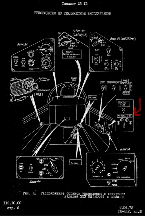
The panel for switching 'Литер' frequency is below, there's four of these frequencies, correspond to the new developed transmitter.
The "Литер" frequencies are also mentioned in the literatures about R-23 and R-24, for example:

https://missilery.info/missile/r23:Важным новшеством ГСН стала и возможность автоматической подстройки ее гетеродина под литерную частоту РЛС самолета-носителя. В итоге отпала необходимость литерного исполнения ракет.
 

Attachments

  • 1765642108351.png
    1765642108351.png
    796.9 KB · Views: 43
100kHz - See the #44 reply of this post.:)

Yes, I know for that , tnx.

''Here the PRF is 1 KHz and 5 KHz. The quasi-continuous frequency is 100 KHz; it is used only in guiding the R-23R and R-24R Semi Active Radar Homing Missiles. ''

He meant on PRF for sure but 100, maybe it was 10kHz ???
 
Yes, I know for that , tnx.

''Here the PRF is 1 KHz and 5 KHz. The quasi-continuous frequency is 100 KHz; it is used only in guiding the R-23R and R-24R Semi Active Radar Homing Missiles. ''

He meant on PRF for sure but 100, maybe it was 10kHz ???
I'm wondering the exact value too:)))
 
'Quasi-continuous' is high PRF / FMICW.
High-PRF is typically at least 180kHz-200kHz.
A 10KHz PRF illumination mode makes no technical sense at all. The advantage of CW - it's continuously transmitting. A High-PRF radar can approach a 50% duty cycle = transmitting half the time.
 
'Quasi-continuous' is high PRF / FMICW.
High-PRF is typically at least 180kHz-200kHz.
A 10KHz PRF illumination mode makes no technical sense at all. The advantage of CW - it's continuously transmitting. A High-PRF radar can approach a 50% duty cycle = transmitting half the time.

Exactly and maybe he /Ahmad/ meant on CWI mode as the CW Illuminaton of the engaged target not the real Quasi-continuous wave method which is used in the search modes, so during searching,scanning of the given scan zone?

So this new 4-frequency transmitter as the CWI channel ,translated as : continuous illumination channel...

''KNP transmitter: 48.5kg (providing STT for R-23R)''

...can only provide that 100 kHz PRF during STT and CWI of the target. In fact ,this KNP provides not only that STT ( lock-on mode) but as mentioned CWI after R-23R/-24R is launched. After launching the main pulse transmitter/klystron ,continues for searching,scanning with LPRF mode.
 

Similar threads

Back
Top Bottom