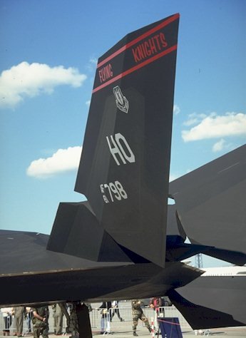
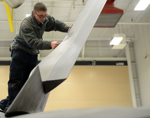
Sukhoi Su-57 flight testing, development & operations [2012-current]

2D (flat) nozzles don't "reduce" thrust.
The area ratio of variable geometry nozzles changes in flight so that the nozzle operates near perfect isentropic expansion, where the gross thrust coefficient (F/Fi) is almost 1 (given the unavoidable losses due to angularity, friction, leakages...). 2D nozzles behave like the axisymmetric ones (some shock pattern are different tbf), and both output 99% of the ideal thrust.
A reduction in 5% would be massive, a value you can encounter in conditions of moderate under/over-expansion.


That’s cool but flat nozzles still definitely lose thrust. It been documented in various studies including ones done by NASA. Your argument is like claiming there is no ‘fire’ in a combustion engine…..it’s actually rapid thermal expansion where opposing force cancels out to create force transmission through a drive shaft.

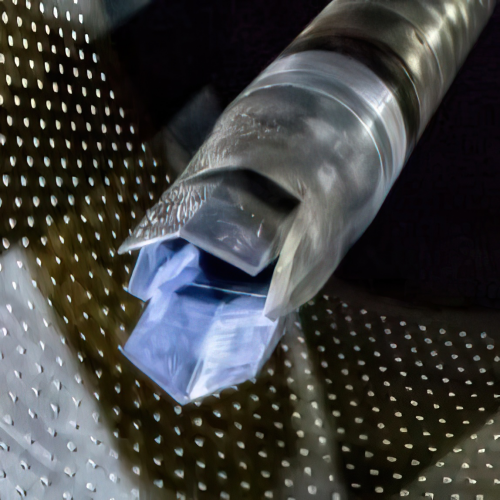
 
The paper you sent evaluates the nozzle divergence coefficient, aka angularity losses. That is a simple, unavoidable phenomenon caused by the jet at the exit not having the sole axial component. As the nozzle secondary half angle increases, you lose more forward thrust. If you make the nozzle longer, the angle decreases and divergence coefficient tends to one. This is for both axisymmetric and 2D.
On page 16 you can even see the trend of the coefficient, where it is clear that 2D nozzle has always less angularity losses (and that should be obvious since you have only two ramps moving, with the side walls keeping the jet axial).
That’s cool but flat nozzles still definitely lose thrust
Again, the 2D nozzle behaves like an axisymmetric one, with almost the same losses (around 1%). Plug nozzles don't, and generally have lower efficiency.
You claimed that the thrust of the F119 would be at least 5% higher if a non-2D nozzle were used, a value you can’t achieve by simply using a different nozzle. The thrust you lose is due to friction, angularity, expansion, leakage and cooling air throttling loss, which are present in all nozzle configurations. Afaik there aren't phenomena that appear only in the 2D nozzle that make it "definitely lose thrust" more than in the axisymmetric. Once the area and pressure ratios are defined, the axisymmetric and the 2D nozzle will output almost the same thrust.
You can take a look at this paper https://ntrs.nasa.gov/citations/19800015775
In summary, for the test conditions of this investigation, the SERN and 2-D C-D nozzles generally produce higher and the wedge nozzle generally produces lower thrust minus-drag performance than the axisymmetric nozzle base-line configuration.
The tricky part is the integration of the nozzle in the fuselage, that's when you have differences in aft-end drag and you may choose 2D over ax (speaking of performance only, not radar/IR signature).
 
The inherent design challenges of a 2D nozzle are the increased surface area vs a round nozzle (increased surface drag, more area to be cooled), and the structural inefficiencies of flat surfaces in a pressure vessel (pressure loads cause bending loads). However, a vectoring 2D nozzle has the inherent advantage of being able to control the convergent to divergent area ratio for optimum supersonic expansion at varying nozzle pressure ratios.

One of the practical challenges of the 2D nozzle is sealing leakage paths where the pressurized exhaust flow escapes instead of exiting the exhaust thru the nozzle. This reduces the discharge coefficient, reducing the potential thrust. A lot of effort was put into the F119 nozzle development to minimize flow leakage.
 
I would say yes, although the divergent flap transitioning from flat at the convergent throat to a shallow V at the trailing edge is different. The resulting Hexagonal shape of the nozzle, rotated 15 degrees to each side of the aircraft, does not seem to be optimal for LO surface alignment. There may be aero advantages to that arrangement.
 
It would appear that all 6 surfaces of the divergent section of the nozzle are aligned with neither wings, horizontal stabs, vertical stabs, nor airframe sidewall. They appear to generate reflections in 6 new directions.
 
The paper you sent evaluates the nozzle divergence coefficient, aka angularity losses. That is a simple, unavoidable phenomenon caused by the jet at the exit not having the sole axial component. As the nozzle secondary half angle increases, you lose more forward thrust. If you make the nozzle longer, the angle decreases and divergence coefficient tends to one. This is for both axisymmetric and 2D.
On page 16 you can even see the trend of the coefficient, where it is clear that 2D nozzle has always less angularity losses (and that should be obvious since you have only two ramps moving, with the side walls keeping the jet axial).

Again, the 2D nozzle behaves like an axisymmetric one, with almost the same losses (around 1%). Plug nozzles don't, and generally have lower efficiency.
You claimed that the thrust of the F119 would be at least 5% higher if a non-2D nozzle were used, a value you can’t achieve by simply using a different nozzle. The thrust you lose is due to friction, angularity, expansion, leakage and cooling air throttling loss, which are present in all nozzle configurations. Afaik there aren't phenomena that appear only in the 2D nozzle that make it "definitely lose thrust" more than in the axisymmetric. Once the area and pressure ratios are defined, the axisymmetric and the 2D nozzle will output almost the same thrust.
You can take a look at this paper https://ntrs.nasa.gov/citations/19800015775

The tricky part is the integration of the nozzle in the fuselage, that's when you have differences in aft-end drag and you may choose 2D over ax (speaking of performance only, not radar/IR signature).


Flat nozzles have more area given the same engine diameter, when you have more area you have more friction which causes more boundary layers and loss of thrust because that thermal energy equates to kinetic energy which will be lost due to the friction. However, that is one of many issues, as there is also flow separation from corners which causes uneven pressure especially in the divergent area of the nozzle. With round symmetrical nozzles you theoretically have uniform flow but your argument is that by installing a square nozzles you have almost no loss? This despite major disruption of gas around corners as well as the area of divergence which means more friction and boundary layers and uneven pressure.

And I am not even mentioning thrust vectoring which will cause even greater loss. One study cites 10% loss when the nozzle deflects and one of the issues is none uniform flow and divergence which also exists even when there is no deflection. The F-119 engine (or SU-57 engines) are slaved with the flight control computers which job is to keep the aircraft from falling out of the sky, that is the stabilizers and nozzles are constantly moving so yes there is definitely a loss in thrust not only in the inherent loss of efficiency of flat nozzles designs themselves but TVC deflection. I didn’t mince my words when I spoke about a 5% loss in thrust. I even used an AI tool and it constantly predicted flat nozzles lose 3% to 10% based on data it collected with likely 10% counting deflection or deflection plus flat nozzle design.

 
Yes, thrust vectoring will reduce the forward facing thrust by the sine of the vector angle, simple geometry. This is the same for both 2D and Axisymmetric vectoring nozzles. The total thrust is not decreased, just used in a different direction to provide the vectoring flight control, which is the whole reason to have thrust vectoring.

This effect is relatively small. At the full 20 degrees vector angle of the F119, the forward thrust loss is about 9%, while about 40% of the thrust is acting in the vertical direction. At a more common vector angle of 5 degrees, the forward thrust loss is less than 4%.

At supersonic speeds, a slight vector angle can be used to offset the nose down trim that occurs when the center of lift moves aft. This reduces the amount of download required on the horizontal tail, with the reduction in drag more than offsetting the reduction in thrust from the trim vector. The reduced deflection of the horizontal tail also allows for improved supersonic maneuverability in both both pitch and roll.
 
I would say yes, although the divergent flap transitioning from flat at the convergent throat to a shallow V at the trailing edge is different. The resulting Hexagonal shape of the nozzle, rotated 15 degrees to each side of the aircraft, does not seem to be optimal for LO surface alignment. There may be aero advantages to that arrangement.

Rotating the nozzles should not have any noticeable effect on RCS since the nozzles are at the very rear where the electronic energy (EM) energy will be scattered and redirected to the sides with an offset angle. The F-117 used the same methods but to a more extreme level where the EM scattered in dozens of directions at various areas of the aircraft ie: front, sides, top, rear, ect. Those faceted areas also created corner reflectors.

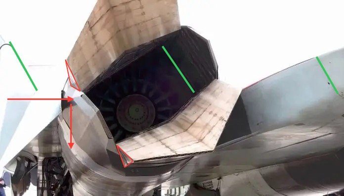
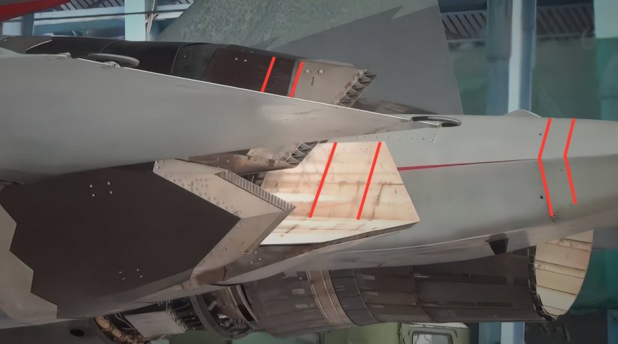
In fact rotating the nozzles actually lower the RCS from the side hemisphere for two reasons. Firstly the side nozzle itself it almost flat so if they aligned the engines at zero offset it would create a 90 degree angle; moreover, the nozzles themselves would create 90 degree corners at deflection or divergence (red wedge shapes in the background photo). It was absolute necessary to rotate the nozzles or have a large RCS from the 90 degree corners. The nozzles themselves also have perfect platform alignment with the rest of the aircraft ie: the green lines in the photo.

IMG_2256.jpeg
 
The nozzles themselves also have perfect platform alignment with the rest of the aircraft ie: the green lines in the photo.
Not sure, an almost 5 degree difference is not what I would call perfect alignment.
 
Rotating the nozzles should not have any noticeable effect on RCS since the nozzles are at the very rear where the electronic energy (EM) energy will be scattered and redirected to the sides with an offset angle. The F-117 used the same methods but to a more extreme level where the EM scattered in dozens of directions at various areas of the aircraft ie: front, sides, top, rear, ect. Those faceted areas also created corner reflectors.

In fact rotating the nozzles actually lower the RCS from the side hemisphere for two reasons. Firstly the side nozzle itself it almost flat so if they aligned the engines at zero offset it would create a 90 degree angle; moreover, the nozzles themselves would create 90 degree corners at deflection or divergence (red wedge shapes in the background photo). It was absolute necessary to rotate the nozzles or have a large RCS from the 90 degree corners. The nozzles themselves also have perfect platform alignment with the rest of the aircraft ie: the green lines in the photo.

View attachment 768541

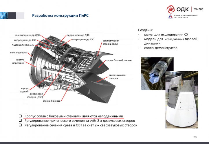
If you meant on the rotation of the nozzle by the longitudinal axis, that is not the case. Btw ,I also meant that but it was mistake. Nozzle itself is fixed.

Su-57 new engine 4 mod.png

The flame holders look to be a Al-51F

Is there any photo of that part of the AL-51F which we can see ?
 
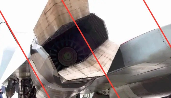
Is this a joke? That’s not how platform alignment in context of stealth work


I know what platform alignment. Next time if you want to quote me don’t ask rhetorical questions and waste my time. Platform alignment is when aircraft follows rules of consistent angles of geometry in order to redirect electromagnetic energy (EM) away in a consistent manner. Such as leading edges, trailing edges or other structures with the sole purpose of aligning at the same angles.

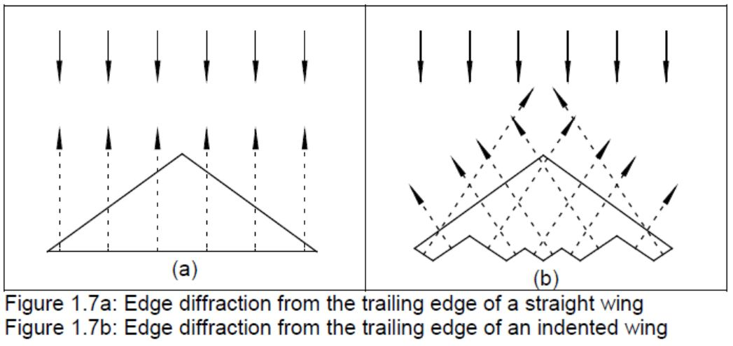
And I didn’t mince words when I said spoke about nozzles having platform alignment because it is exactly the same thing but instead of edge diffraction, shaping and canting surfaces such as fuselage, vertical stabilizers, canopy, ect redirect EM energy through specular reflection.

Platform alignment can literally be any parts of the aircraft parts aligning so as long as the EM energy is redirected in a consistent manner in as few directions as possible regardless of specular reflection or edge diffraction.

IMG_2872.png


IMG_2262.jpeg
 
Are y'all unironically trying to gauge the presence/absence of edge alignment based on less than a handful of pictures of less than ideal quality and angle?

Seems to me like something that leads nowhere, compared to simply waiting for more info, schematics, photo material etc.

It's pretty much a given that such information will sooner or later surface in either a UAC press release or in schematics attached to a patent.

This multi-page argument seems rather pointless imho
 
Last edited:
Rotating the nozzles should not have any noticeable effect on RCS since the nozzles are at the very rear where the electronic energy (EM) energy will be scattered and redirected to the sides with an offset angle. The F-117 used the same methods but to a more extreme level where the EM scattered in dozens of directions at various areas of the aircraft ie: front, sides, top, rear, ect. Those faceted areas also created corner reflectors.

In fact rotating the nozzles actually lower the RCS from the side hemisphere for two reasons. Firstly the side nozzle itself it almost flat so if they aligned the engines at zero offset it would create a 90 degree angle; moreover, the nozzles themselves would create 90 degree corners at deflection or divergence (red wedge shapes in the background photo). It was absolute necessary to rotate the nozzles or have a large RCS from the 90 degree corners. The nozzles themselves also have perfect platform alignment with the rest of the aircraft ie: the green lines in the photo.
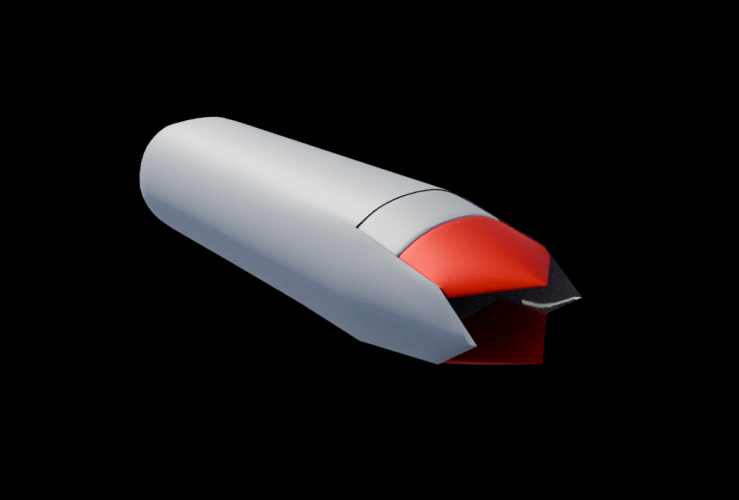
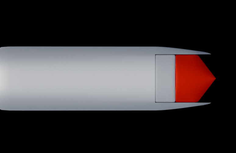
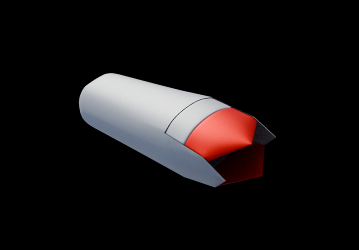
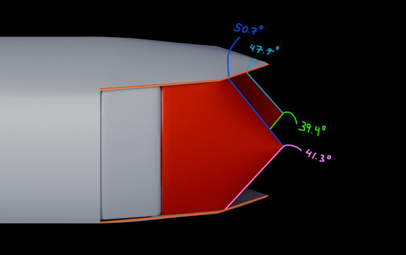
Rotating this nozzles will result in a measurable impact on RCS. I have procured a model to demonstrate:
1746304429358.png 1746304598079.png
This model is a rough replication of the nozzle we speak of in a 3D software. I have highlighted the two main nozzle parts in red, and have swept their TE angles to 42 degrees. The specificity of this number does not matter and simply serves the demonstration. When we view the model from a top-down view, we see that the red edges are properly aligned and will delegate edge diffraction to two specific aspects.

Now, let's rotate the nozzle by 25 degrees (eyeballed off of SU57 pictures):
1746304788439.png Screenshot 2025-05-03 145313.png
Focusing SOLELY on the nozzle alignment, we have successfully generated 4 new aspects of edge diffraction return. Not to mention, every 0-degree angle (highlighted in orange) now has a new sweep angle, further degrading side aspect return.
(DISCLAIMER: I have an underlying assumption that the sweep angles of the Nozzle TE are the SAME. This is as dissimilar sweep angles would result in a somewhat lopsided nozzle, which is not apparent in any photos so far).

I hope this made it somewhat easier to understand. Thank you.
 
I know what platform alignment. Next time if you want to quote me don’t ask rhetorical questions and waste my time. Platform alignment is when aircraft follows rules of consistent angles of geometry in order to redirect electromagnetic energy (EM) away in a consistent manner. Such as leading edges, trailing edges or other structures with the sole purpose of aligning at the same angles.

And I didn’t mince words when I said spoke about nozzles having platform alignment because it is exactly the same thing but instead of edge diffraction, shaping and canting surfaces such as fuselage, vertical stabilizers, canopy, ect redirect EM energy through specular reflection.

Platform alignment can literally be any parts of the aircraft parts aligning so as long as the EM energy is redirected in a consistent manner in as few directions as possible regardless of specular reflection or edge diffraction.

View attachment 768725


View attachment 768726
Good job on the definition. So now how does it go from the definition you just gave to the picture of the red lines you drew over the nozzle?

What you drew was the tilt axis of the nozzle seemingly aligning with the surfaces of the tail cone, not the actual outer surfaces of the nozzle flaps which is what relevant here when it comes to aligning specular returns. The only alignment the tilt provide is inner surfaces of the nozzle flaps but those will bounce off other surfaces deeper inside the engine, altering the angles of return
 
Last edited:
Good job on the definition. So now how does it go from the definition you just gave to the picture of the red lines you drew over the nozzle?

What you drew was the tilt axis of the nozzle seemingly aligning with the surfaces of the tail cone, not the actual outer surfaces of the nozzle flaps which is what relevant here when it comes to aligning specular returns. The only alignment the tilt provide is inner surfaces of the nozzle flaps but those will bounce off other surfaces deeper inside the engine, altering the angles of return

What is the “outer surface of the nozzle flap”? I illustrate everything I speak about while you speak in vague terms that are open to interpretation. So you are talking about electromagnetic energy bouncing off the inner nozzle? Okay and how is that different to any other nozzle from say an F-35 or F-22? We can also see the insides of those nozzles.

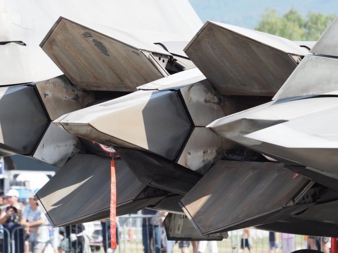
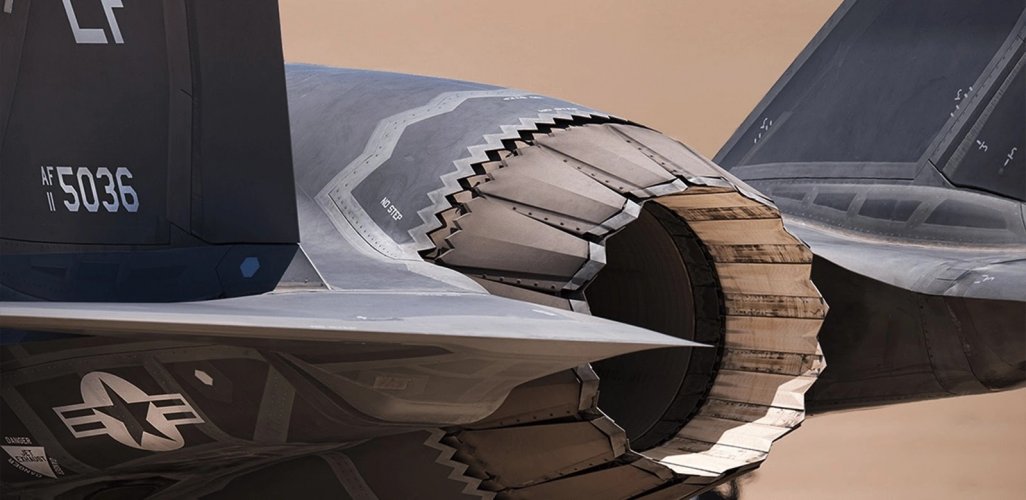
The following pictures illustrates the inside of those aircraft nozzles, notice the F-22 has a lot more gaps and seems around the nozzle as it is just a messy design with more areas of both specular and edge diffraction. The F-22s engines are of a mess:

IMG_2266.jpeg IMG_2267.jpeg


Here is the inside of the SU-57 nozzle, it has angled symmetry to the rest of the aircraft. From this angle the EM energy would be directed at the same angle as any surface. The argument can be made that at certain angles there might be a chance of EM bouncing off multiple surfaces and making it back to a radar but the same argument can be made for any stealth aircraft’s nozzle and this is an unlikely scenario as the aircraft is dynamic and moving in space so even if a radar is close enough and directed at the nozzles it may not be a strong enough return nor would it last more than milliseconds.

IMG_2263.jpeg

Rotating this nozzles will result in a measurable impact on RCS. I have procured a model to demonstrate:
View attachment 768728View attachment 768729
This model is a rough replication of the nozzle we speak of in a 3D software. I have highlighted the two main nozzle parts in red, and have swept their TE angles to 42 degrees. The specificity of this number does not matter and simply serves the demonstration. When we view the model from a top-down view, we see that the red edges are properly aligned and will delegate edge diffraction to two specific aspects.

Now, let's rotate the nozzle by 25 degrees (eyeballed off of SU57 pictures):
View attachment 768730View attachment 768732
Focusing SOLELY on the nozzle alignment, we have successfully generated 4 new aspects of edge diffraction return. Not to mention, every 0-degree angle (highlighted in orange) now has a new sweep angle, further degrading side aspect return.
(DISCLAIMER: I have an underlying assumption that the sweep angles of the Nozzle TE are the SAME. This is as dissimilar sweep angles would result in a somewhat lopsided nozzle, which is not apparent in any photos so far).

I hope this made it somewhat easier to understand. Thank you.

But the SU-57 nozzles are totally different in design as the outer side walls align with the top of the nozzles while your illustration shows the side walls pushed back. Thats is incorrect as we have videos/photos showing everything seemingly aligned. For reference the last picture I posted above shows this.


Your argument can be made for anything such as a flap, ruder, moving tail, ect as when they move they have different symmetry at any given time such an example is this:


IMG_2270.jpeg


Speaking of F-117 it actually had very poor edge alignment as many of the surfaces were not aligned with each other. The J-20 also has surfaces that do not align but that doesn’t mean those aircraft have poor stealth, it just means the radar scatters EM energy in more areas. For today’s the F-117 of course has worse stealth but that’s because it is an outdated design with more surface areas and corner reflectors.
 
that doesn’t mean those aircraft have poor stealth, it just means the radar scatters EM energy in more areas.
That means... worse stealth :)

F-117A concentrated on front RCS. It has many spikes. It didn't use edge alignment.

B-2 achieved all aspect stealth using a 4 spike edge alignment design.

The highest level of stealth is a still a 4 spike design. Any more directions than 4 is "worse stealth".

There's a reason the B-21 is a 4 spike design.


You are not wrong but there is some nuance, designers want to have as simple of a design as possible to minimize the chances for radar return but that is not always possible based on requirements. More diffraction in more areas theoretically means higher chances of being picked up by radar but at the same time that is improbable unless you have radars overhead, to the sides, underneath ect knowing there is a stealth aircraft in a certain area while they focus their beams in a tighter area for higher resolution and power.

The B-21 also has a smooth recessed intake while the B-2 has a raised intake with sharper edges, the exhaust is also smaller and a 3 sided design as opposed to 4 sided, the aircraft itself is also smaller making harder to see with certain bandwidths.

This is why I always argued against the round serrated SU-57 nozzles, although better than a regular round nozzle they also had dozens of gaps between each pedal while they created lots of diffraction in all different directions.
 
Canted 2D nozzles were a feature of the as-yet-unseen Rockwell ATF. They were canted at 45 degrees to avoid the square side giving a 90 degree return to the side and align to the canted fuselage. This was due to similar circumstances to the Su-57 - 2D nozzles replacing circular nozzles of the earlier design in an exposed location.

rockwell-atf-jpg.161440

rockwellstealthconcept-jpg.141722

l-86-856-jpg.371427
 
Last edited:
But the SU-57 nozzles are totally different in design as the outer side walls align with the top of the nozzles while your illustration shows the side walls pushed back. Thats is incorrect as we have videos/photos showing everything seemingly aligned. For reference the last picture I posted above shows this.

Your argument can be made for anything such as a flap, ruder, moving tail, ect as when they move they have different symmetry at any given time such an example is this:


View attachment 768837


Speaking of F-117 it actually had very poor edge alignment as many of the surfaces were not aligned with each other. The J-20 also has surfaces that do not align but that doesn’t mean those aircraft have poor stealth, it just means the radar scatters EM energy in more areas. For today’s the F-117 of course has worse stealth but that’s because it is an outdated design with more surface areas and corner reflectors.
1. The exact alignment of model parts does not matter. You still have at least 6 new aspects for radar return when the nozzle is rotated. For all that matters, I could have shown only the red part.

2. You are correct about all-rotating tail surfaces. This is why many LO designs either opt out of tails, or use smaller, part actuated surfaces at the end of the tail. Good designs will also come with software that will allow pilots inputs to minimize control surface movement to overcome increased return as a result of control surface actuation. The SU-57 decision to use an all moving tail was a logical engineering decision based on aircraft performance requirements. Not sure what else to put here.


It’s a ‘flat’ nozzle, rotating it doesn’t change anything other than eliminating a 90 degree angle, the argument can be made that from some angles the inter wall of the nozzle is visible but the problem with that argument is that it’s canted anyways and partially obscured from the side by the base of the vertical stabilizer, but pointing a radar at or looking at a nozzle/inside an engine will inherently cause increased RCS. By your logic we can also claim from certain angles the F-22 nozzles has 10 or 20 new “aspects for radar return” which would be correct. The logic has to either apply to all aircraft engines/nozzles or none, it can’t apply to one but not another.

As for all moving tails, the YF-23 had them, the J-20, SU-75, F-117, SR-72 all have them. Having traditional rudders doesn’t mean lower RCS, in fact there is a rudder and it’s seam/gap that runs the length of the wing. That seam/gap doesn’t exist of an all moving stabilizers instead a seam/gap exists at the base were the wing rotates making it less exposed to radiation at certain angles plus it’s a smaller gap as it only runs from leading edge to trailing edge. Moreover, the vertical stabilizers that are all moving can afford to be smaller and make smaller inputs but have similar or better pitch/yaw authority.
Ironically the F-22 also has a gap at the lower base stabilizer but it’s fixed. So is a traditional rudder better for RCS? Absolutely not

So we have the length of the rudder and its seam, the gap when it’s deflected and the fixed gap at the base. The F-22 has a lot of superior design elements compared to the SU-57 but the rudder is not one of them.

IMG_2271.jpeg
 
Last edited:
Rotating this nozzles will result in a measurable impact on RCS. I have procured a model to demonstrate:
View attachment 768728View attachment 768729
This model is a rough replication of the nozzle we speak of in a 3D software. I have highlighted the two main nozzle parts in red, and have swept their TE angles to 42 degrees. The specificity of this number does not matter and simply serves the demonstration. When we view the model from a top-down view, we see that the red edges are properly aligned and will delegate edge diffraction to two specific aspects.

Now, let's rotate the nozzle by 25 degrees (eyeballed off of SU57 pictures):
View attachment 768730View attachment 768732
Focusing SOLELY on the nozzle alignment, we have successfully generated 4 new aspects of edge diffraction return. Not to mention, every 0-degree angle (highlighted in orange) now has a new sweep angle, further degrading side aspect return.
(DISCLAIMER: I have an underlying assumption that the sweep angles of the Nozzle TE are the SAME. This is as dissimilar sweep angles would result in a somewhat lopsided nozzle, which is not apparent in any photos so far).

I hope this made it somewhat easier to understand. Thank you.

There actually seem to be two schools of thought in this regard. The conventional wisdom that you are using here (exemplified by the F-22 and F-23) holds that you need to align the plan projection of the edges in question. But if you look at the newer F-35 in detail, you'll find that it appears to simply sweep the edges to be aligned at the same angle in their respective planes (e.g. the upper lip of the intake and wing LE). According to that approach, canting the nozzles would be fine?
 
Last edited:
The following pictures illustrates the inside of those aircraft nozzles, notice the F-22 has a lot more gaps and seems around the nozzle as it is just a messy design with more areas of both specular and edge diffraction. The F-22s engines are of a mess:

From earlier:
Those photos do show the nozzle full open at ground idle. They are not that open even in full AB (where the thermal image is highly visible), and are much further closed at Mil and below. And there is no vectoring at mid to high airspeeds, making the nozzle virtually invisible to radar in the aft sector.
 
From earlier:


All the ground idle in the world won’t hide an inherently messy design with dozens of gaps/seams, discontinies, ect at and around the nozzles. This conversation is not about the F-22 anyways. There are some comparisons and references to the a F-22 but this not a F-22 thread. The F-22s design is great but it’s far from ideal especially the nozzles/rear. The YF-23 had much better RCS and nozzles, the SU-57 has a much simpler cleaner nozzle and tail design with smaller movable stabilizers. Its probably the only area where theoretically the SU-57 has a smaller RCS but of course once you go past the nozzles/tails the SU-57 has worse design features (canopy, round sensors, minimal serrated panels, ect) which will impact its RCS including in the rear hemisphere.
 
I will tell you that the F119 has an assigned signature budget for the front end and back end of the engine as part of the total F-22 signature. There is a program that assesses any defects against that budget, and it easily meets that serviceability target for the vast majority of the time. I don’t see that capability in the released photos of new Su-57 engine with the 2D nozzle.
 
As for all moving tails, the YF-23 had them, the J-20, SU-75, F-117, SR-72 all have them.

Two of the aircraft you have listed here have not flown. Another was a prototype.

As for all moving tails, the YF-23 had them, the J-20, SU-75, F-117, SR-72 all have them. Having traditional rudders doesn’t mean lower RCS, in fact there is a rudder and it’s seam/gap that runs the length of the wing. That seam/gap doesn’t exist of an all moving stabilizers instead a seam/gap exists at the base were the wing rotates making it less exposed to radiation at certain angles plus it’s a smaller gap as it only runs from leading edge to trailing edge.

All moving stabilizers have a considerably larger discontinuity than other traditional rudder systems.

You claim that the gap at the base of an all-moving stabilizer is "less exposed to radiation at certain angles." I would be interested in learning about these "certain angles." The discontinuity at the base of an all-moving tail generates returns at all aspects where the top of the aircraft is visible. So, unless these "certain angles" are ones where the tails are not visible at all, this statement is nonsensical.

I will add that the gaps of a traditional rudder are not visible from the frontal aspect. Or a side aspect. Maybe even some rear aspects. This is not the case for the all-moving tail.

Additionally, we should remember that the F-22 and Su-57 had different design goals. They are optimized for different requirements, and I personally find that comparisons between the two are in poor taste. Apples and Oranges.
 
Last edited:
What is the “outer surface of the nozzle flap”? I illustrate everything I speak about while you speak in vague terms that are open to interpretation. So you are talking about electromagnetic energy bouncing off the inner nozzle? Okay and how is that different to any other nozzle from say an F-35 or F-22? We can also see the insides of those nozzles.

The following pictures illustrates the inside of those aircraft nozzles, notice the F-22 has a lot more gaps and seems around the nozzle as it is just a messy design with more areas of both specular and edge diffraction. The F-22s engines are of a mess:

View attachment 768834View attachment 768835


Here is the inside of the SU-57 nozzle, it has angled symmetry to the rest of the aircraft. From this angle the EM energy would be directed at the same angle as any surface. The argument can be made that at certain angles there might be a chance of EM bouncing off multiple surfaces and making it back to a radar but the same argument can be made for any stealth aircraft’s nozzle and this is an unlikely scenario as the aircraft is dynamic and moving in space so even if a radar is close enough and directed at the nozzles it may not be a strong enough return nor would it last more than milliseconds.

View attachment 768836


But the SU-57 nozzles are totally different in design as the outer side walls align with the top of the nozzles while your illustration shows the side walls pushed back. Thats is incorrect as we have videos/photos showing everything seemingly aligned. For reference the last picture I posted above shows this.
NO I'm saying the inner walls of the su-57 DO have platform alignments. What I criticized is the original illustration that you drew which did NOT show platform alignments but rather alignment of the imaginary tilt axis of the nozzles to that of the surface angle of the tail cone.

I don't know why you brought the f-22 into this. Since my post was never about f-22 vs su-57. However, since you mentioned it, it's important to note that the aft section of the f-22 cover the engine entirely from the side.

As for the 2nd picture with your illustrations quoted in this very post it's too early to tell if the alignments there are in fact aligned. Your original illustration that I criticized though clearly showed the outer surface angles, due to the faceting, are not, in fact, aligned with the tail cone, which is fine. It is a good compromised solution to marry the circular aft to a semi faceted edge to avoid heavy and complex and exotic RAS or RAM solutions aka f-35. I'm actually impressed with sukhoi for turning a nightmare situation where the engineers and the military are not on the same page (air force want flat nozzle while sukhoi want to not making major change to the aft shape) to a manageable solution.
 

Attachments

  • Sukhoi_Su-57-e1734006583128.png
    Sukhoi_Su-57-e1734006583128.png
    509.8 KB · Views: 17
Two of the aircraft you have listed here have not flown. Another was a prototype.


All moving stabilizers have a considerably larger discontinuity than other traditional rudder systems.

You claim that the gap at the base of an all-moving stabilizer is "less exposed to radiation at certain angles." I would be interested in learning about these "certain angles." The discontinuity at the base of an all-moving tail generates returns at all aspects where the top of the aircraft is visible. So, unless these "certain angles" are ones where the tails are not visible at all, this statement is nonsensical.

I will add that the gaps of a traditional rudder are not visible from the frontal aspect. Or a side aspect. Maybe even some rear aspects. This is not the case for the all-moving tail.

Additionally, we should remember that the F-22 and Su-57 had different design goals. They are optimized for different requirements, and I personally find that comparisons between the two are in poor taste. Apples and Oranges.


Point 1: I meant to say SR-71, and regardless many aircraft have used all moving stabilizers including some of the lowest LO designs to date.

Point 2: the discontinuity is not any bigger it’s just moved to the base of the stabilizer. There are many reasons a traditional rudder design is not optimal for LO:

1. The rudder when moved creates a corner reflector with the stabilizer. The more deflection the higher the intensity which runs top to bottom. All movable stabilizers have no corner reflectors.

2. The all movable vertical stabilizer only has a narrow steam when viewed from the front or back, on the other hand a rudder runs vertically meaning from the front and back you have a seam that runs the length of the stabilizer. This is the same argument people make for the F-22 canopy having better stealth….it omits the canopy bow. It’s one continuous surface hence why the Raptor’s single piece canopy is regarded as having a smaller RCS and rightfully so.

3. All movable stabilizers have twice the force per degree of movement, meaning they can move 50% less but accomplish the same result. Less movement less RCS.


Point 3. All moving vertical stabilizers theoretically have better stealth in literally every hemisphere compared to traditional rudder designs, front, back and everything in between. Especially from lower angles where the lower half of the stabilizer is obscured by the wings or lower fuselage.


Point 4. That is wrong. From the front even if the rudder gap is not visible to the eyes electromagnetic energy will reflect back if it’s perpendicular to the rudder.
 
Back
Top Bottom