For a puller engine, yeah, but pusher engines need to be toe in for that to work, like on the su-35 and su-57. I would expect toe out to make single engine yaw even worse.litzj said:Phos said:Does anyone know what the benefit of jet engines in a tow out arrangement is?, Both the F-23 EMD and NATF-23 have the arrangement. I get that having them toe in helps in engine out situations, but that obviously isn’t the case for toe out.
less momentum when one of them is in flame out?

You are using an out of date browser. It may not display this or other websites correctly.
You should upgrade or use an alternative browser.
You should upgrade or use an alternative browser.
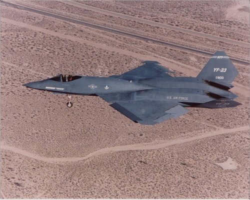
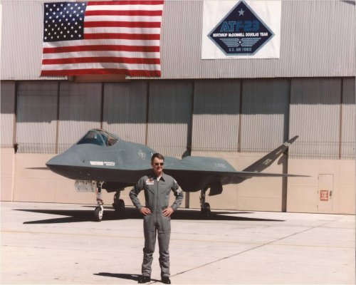
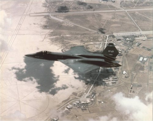
Northrop / McDonnell Douglas ATF - YF-23 and EMD F-23
- Thread starter Matej
- Start date
It looks to me that the chines didn't shrink, everything else grew into them. I wanna say they generate compression lift? I'm no expert but I think the bottom is the part that matters.Steven said:When comparing the F-23 DWGs with the YF-23, it appears that the chines on the F-23 are substantially more subdued than on the YF-23. I wonder what effect that has on vortex generation at high alpha; I would think that it would be less than on the YF-23. Is there anything on the high alpha testing or modeling of the YF-23 to give insight as to why the chines were altered?
Phos said:Does anyone know what the benefit of jet engines in a tow out arrangement is?, Both the F-23 EMD and NATF-23 have the arrangement. I get that having them toe in helps in engine out situations, but that obviously isn’t the case for toe out.
The F-23's arrangement does create a worse yawing moment due to asymmetric thrust. My guess is that they had sufficient confidence in the reliability of the engines to go with that arrangement in order to improve volume distribution and area ruling.
- Joined
- 22 October 2006
- Messages
- 338
- Reaction score
- 76
HangarB Productions F-23 model, is up for sale at sketchfab. Even if the model is not true to the F-23A EMD, this is one of the rare F-23 model of high quality and can be used as a starting point for modification into the EMD version.
- Joined
- 22 October 2006
- Messages
- 338
- Reaction score
- 76
You have the most recent and accurate one in paul metz YF-23 book @air force legends.Would anyone happen to have the unclassified technical drawings? I'm attempting to create a 1:12 scale flying replica. I have one sheet in high quality, and a few in that are almost impossible to read.
That plan is a beauty.
Please there is one thing I don't understand, does the part I point on this crop means that the V-Tail could be rotated down to 37° and 17.1° for storage ?
Please there is one thing I don't understand, does the part I point on this crop means that the V-Tail could be rotated down to 37° and 17.1° for storage ?

OkLol, no. It just shows clearances.
") thks
thks- Joined
- 19 July 2016
- Messages
- 4,279
- Reaction score
- 3,463
The only link I can imagine between those two is wheels, wings and gear.

- Joined
- 2 August 2006
- Messages
- 3,255
- Reaction score
- 1,527
With regard to the area in red I figured three things:
1) There is something about the way all of the radar waves bounced around in the duct that made that not a problem.
2) They didn't expect any radar signals to be coming from head on at the same altitude, due to it's operational altitude. All of the radar waves from in front would be from well below the waterline of the aircraft.
3) They were going to incorporate some sort of fan blocker that didn't need to be shown in these drawings.
Dr Aircraft
ACCESS: Restricted
- Joined
- 22 May 2019
- Messages
- 10
- Reaction score
- 34
- Joined
- 22 October 2006
- Messages
- 338
- Reaction score
- 76
WMOF, roy martin presentation of the YF-23 flying qualities
Excellent as always
- Joined
- 1 April 2006
- Messages
- 11,394
- Reaction score
- 10,294
You really gotta be centered up just perfectly to get a look at the compressor blades. Even just slightly askew and that little red spot will vanish. I don't think they would be visible except in engineering drawings. And perhaps maybe they were going to use coatings like on the tu160 blades. Or perhaps there's a slight bump inside the ducts to hide the redspot that's not in these public drawingsWith regard to the area in red I figured three things:
1) There is something about the way all of the radar waves bounced around in the duct that made that not a problem.
2) They didn't expect any radar signals to be coming from head on at the same altitude, due to it's operational altitude. All of the radar waves from in front would be from well below the waterline of the aircraft.
3) They were going to incorporate some sort of fan blocker that didn't need to be shown in these drawings.
- Joined
- 22 October 2006
- Messages
- 338
- Reaction score
- 76
Why do you want a three view? as tomcat said, there are a lot of programs that open .obj files, so you can make your own 3-view, and mess with the weapon bays to see if they accomodate 6 aim-120cCan you share a better three view of the model?
katuro
ACCESS: Restricted
- Joined
- 19 March 2020
- Messages
- 1
- Reaction score
- 3
I am the author of the model. I would be happy to be introduced to it, but redistribution of the model is a violation of the Usage Policy. Therefore, I request that the link to OneDrive be removed.There has been a well hidden F-23A EMD 3D model out there for months.
Your are supposed to go to the niconico video page, login, then download the F23.zip file, the password is the first flight date of the Yf-23 in the format dd/mm/yyyy .プライベートファイル - BowlRoll
bowlroll.net
Then you have a .pmx file, that is a file for mikumikudance video game, that you can convert to obj easily.
But since I am sure very few of you (if any) have an account to niconico video, below is the link to the obj file (and textures)
The model is the most accurate I have seen, by far. Even weapon bays and cockpit are modelled, there are also many moveable parts.
Last edited by a moderator:
- Joined
- 22 October 2006
- Messages
- 338
- Reaction score
- 76
I am the author of the model. I would be happy to be introduced to it, but redistribution of the model is a violation of the Usage Policy. Therefore, I request that the link to OneDrive be removed.There has been a well hidden F-23A EMD 3D model out there for months.
Your are supposed to go to the niconico video page, login, then download the F23.zip file, the password is the first flight date of the Yf-23 in the format dd/mm/yyyy .プライベートファイル - BowlRoll
Then you have a .pmx file, that is a file for mikumikudance video game, that you can convert to obj easily.
But since I am sure very few of you (if any) have an account to niconico video, below is the link to the obj file (and textures)
The model is the most accurate I have seen, by far. Even weapon bays and cockpit are modelled, there are also many moveable parts.
I have apologised to katuro. Naturally, there was no bad intent behind my post, just to make things easier, while linking to the original source.Sorry, link removed !
Thank you for the moderation.
BDF
ACCESS: Secret
- Joined
- 14 March 2009
- Messages
- 284
- Reaction score
- 424
"Zero-One" from F-16.net shared this on the F-22 forum. Its a interview with Rick Abell who was a civilian working for the AF (or DoD can't remember) during the acquisition of the ATF program. Has some interesting insight into the process and a bit about the two airplanes. For the TLDR crowd he basically says that each airplane had strengths and weakness but he would've been happy with either as the winner. The final decision went to senior AF leadership which to me gives at least some credibility to the speculation that the decision may have boiled down to preserving LM as a airframer, Northrop's poor performance with the B-2 etc etc.
View: https://www.youtube.com/watch?v=_MUK241uZHM&t=3780
Last edited:
Wrong link (there is an extra letter ("S") at the end that should not be there).
Here it is:
View: https://youtu.be/_MUK241uZHM
Here it is:
Last edited:
- Joined
- 29 November 2010
- Messages
- 1,775
- Reaction score
- 3,479
did you forget to add the link?Hi,
a very good article about Northrop F-23 in Le Fana 3/2021,with
early concepts.
- Joined
- 6 November 2010
- Messages
- 5,262
- Reaction score
- 5,514
Le Fana de l'Aviation is a French monthly magazine.
Hesham gave a heads-up of the latest issue's content.
 boutiquelariviere.fr
Hesham gave a heads-up of the latest issue's content.
Le Fana de l'Aviation | Abonnement magazine | Boutique Larivière
Jusqu'à -40% sur l'abonnement du magazine Le Fana de l'Aviation sur la boutique officielle. Abonnez-vous au magazine Le Fana de l'Aviation, une revue moderne qui colle à l'actualité de l'aviation ancienne et qui suit l'évolution de l'histoire. -...
boutiquelariviere.fr
- Joined
- 3 June 2006
- Messages
- 3,094
- Reaction score
- 3,964
Source: http://aviationarchives.blogspot.com/2021/03/northrop-yf-23-black-widow.htmlRon Downey said:
This topic is 30 pages long. If this brochure has been posted before, please let me know, so I can delate this post or move it to a more suitable topic.
Manuducati
ACCESS: Secret
- Joined
- 25 November 2020
- Messages
- 332
- Reaction score
- 1,065
Hi everyone (by the way this is my first post on this forum, easily the most informative one out there, congratulations).
Is it known what happened to the full-scale mock-up of the production model that was used for RCS study? Was it destroyed or preserved somewhere?
It sported an interesting Ferris camouflage consisting of four shades of grey (also seen on Aldo Spadoni three views drawing of the MRF or MultiRole Fighter made in 1992).
Just this year i saw a special on TV about Northrop's model shop and they built a horten flying wing to demonstrate their skills making models for RCS testing. I am pretty sure they said everything that they make is destroyed.Hi everyone (by the way this is my first post on this forum, easily the most informative one out there, congratulations).
Is it known what happened to the full-scale mock-up of the production model that was used for RCS study? Was it destroyed or preserved somewhere?
It sported an interesting Ferris camouflage consisting of four shades of grey (also seen on Aldo Spadoni three views drawing of the MRF or MultiRole Fighter made in 1992).
- Joined
- 6 August 2007
- Messages
- 3,894
- Reaction score
- 5,976
Is it known what happened to the full-scale mock-up of the production model that was used for RCS study? Was it destroyed or preserved somewhere?
it was stored in New Mexico near RATSCAT for a very long time. Probably still there
- Joined
- 6 August 2007
- Messages
- 3,894
- Reaction score
- 5,976
it was stored in New Mexico near RATSCAT for a very long time. Probably still there
Storage area was at 33.541908° , -106.209736° . Between 2009 and 2012 the entire storage area was cleared out, including the YF-23 model. Don't know what happened to it
Manuducati
ACCESS: Secret
- Joined
- 25 November 2020
- Messages
- 332
- Reaction score
- 1,065
Thanks Quellish, I saw those coordinates in another thread and checked but nothing to be seen except a bunch of F-4, T-38 and Uhey's probably used as targets.
- Joined
- 6 August 2007
- Messages
- 3,894
- Reaction score
- 5,976
Look at it before 2010, surrounded by shipping containers near black T-38sThanks Quellish, I saw those coordinates in another thread and checked but nothing to be seen except a bunch of F-4, T-38 and Uhey's probably used as targets.
BDF
ACCESS: Secret
- Joined
- 14 March 2009
- Messages
- 284
- Reaction score
- 424
So I was flipping through Metz's awesome F-23 book and a passage popped out at me that I hadn't seen before; apologies if its been discussed already. Metz stated that the YF-23 had "a bit more" internal fuel than a F-15 with a center line tank. Assuming he's referring to a F-15C, that's almost 18,000lbs. This surprised me as I've always heard, anecdotally admittedly, that the prototypes for both ATFs held close to 25,000lbs. That got me wondering and I started to compare the blueprints for the YF-23 and the F-23A and eye balling it, it wasn't clear that the production jet had much more fuel than the prototype.
The reason I thought this is because the prototype had three huge fuel cells in the Tank 3 group whereas the production jet didn't nearly as much fuel in this area. The other is that they production jet had large tanks on the flanks that were above and below the inlets (Tanks 6 & 7) but it wasn't clear if this was enough to offset the huge tank 3 group on the prototype. Naturally curiosity got the best of me and I broke out CAD to see if I could reasonably calculate the volumes. Couple caveats, I'm not the most experienced in using these programs (I mostly dabble) and I could easily make (and almost certainly did) make mistakes. Because I'm inexperienced and because the blueprints do not show all the geometry I had to make some estimations (particularly for the aforementioned tanks 6 & 7) but I tried to err on the conservative side. The prototype's tanks were easier to model and are probably more accurate. Finally the wing tanks are nearly identical so I didn't compare them. I also omitted the vent tank in the production jet.
The tank groups on the forward fuselage for the prototype held considerably less fuel than the production would have. Tanks 1A, 1B & 2A, 2B held about 39% of what the production jet's. Not only are the production tanks longer, they're considerably deeper. It was obvious from looking at the blueprints but I was surprised it was that much. The tank 3 group (3A, 3B, and 3C) in the prototype were as huge as I thought, 11.4 times the size of the production jet. Obviously these tanks aren't comparable as tank 3 on the production jet was much smaller and that space was overlapped by tank 2 and reduced in overall volume compared to the prototype.
Moving outboard to the inlet tanks the production jet holds a lot of fuel compared to the prototype, roughly 4.5 times. That number may be on the conservative side too as there is some fuel stored in the back half of the inlet cone but I couldn't reliably measure it. The drawings for the prototype was somewhat unclear as well. So what is the overall difference? Omitting the wing tanks, the production jet has about ~ 25% more fuel volume in the fuselage (I got 27.7% to be precise.)
You're probably asking why I haven't given the actual volumes; because I'm not confident in that they're accurate in terms of converting volumes to fuel capacity. It's possible my conversion of volume to weight is wrong but I don't think so. Anyway, the difference in volume is 45.66 cubic feet. The production jet has 207.7 cf and the prototype has 162.05 cf. JP-8 is about 51lbs per 1 cf so as you can see, the numbers don't add up unfortunately. I did go back and double check my work and the volumes I came up with were consistent. So I think they're viable for a basic comparison as opposed to calculating the actual capacity. My guesstimate is that the production jet has somewhere between 20,000 and 22,000lbs internal. Hope this is somewhat interesting. I was surprised that the fuel capacity was so much less than what I've heard but it appears that perhaps the F-22 didn't loose as much fuel vis-a-vis the YF-22. It would be interesting to see how much fuel it had to loose during EMD.
red admiral
ACCESS: Top Secret
- Joined
- 16 September 2006
- Messages
- 1,805
- Reaction score
- 2,377
Raymer's rule of thumb is a factor of 0.85 to account for baffles, pipes, gauges etc that make some of the volume unusable
BDF
ACCESS: Secret
- Joined
- 14 March 2009
- Messages
- 284
- Reaction score
- 424
Oh I know. I don't think the volumes translate directly into x amount of fuel. My personal guesstimate is that it holds bout 15% more useable internal fuel than the prototype. That being said, its possible the production version may have less unusable fuel because it has 3less tanks and would theoretically have less complicated plumbing.Raymer's rule of thumb is a factor of 0.85 to account for baffles, pipes, gauges etc that make some of the volume unusable
Last edited:
- Joined
- 29 November 2010
- Messages
- 1,775
- Reaction score
- 3,479
what is that tiny jet to the left of the YF-23?
Similar threads
-

-
 ASD Preliminary Designs in Splendid Vision, Unswerving Purpose
- Started by XP67_Moonbat
- Replies: 16
-
McDonnell-Douglas ATS, pre-ATF and ATF studies
- Started by flateric
- Replies: 174
-
McDonnell Douglas F101B Voodoo - carrying MIM-23 Hawk Missile
- Started by Jonathan338
- Replies: 11
-
 VFAX (1974) / NACF Projects (Pre F/A-18 concepts)
- Started by overscan (PaulMM)
- Replies: 53