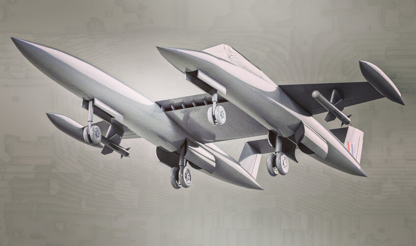
Q. on this - I made a digital model for 3D print a while back and am just updating it to redo in resin rather than FDM
In the picture
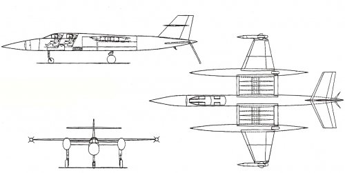
https://www.secretprojects.co.uk/at...pe-20582-20twin-20line-20drawing_1-jpg.61602/ the bomb drawn in seems to overlap with where the right mainwheel bay is. Anyone fathom how or why?
In my attached updated version I interpret the front nosewheels as retracting in different directions between fuselages but haven’t puzzled out either the bombbay or where and how the arrestor hook for the RN version would sit
Hi Lostcosmonauts. Great model!
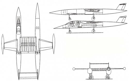
This is how I interpret the drawings:
View attachment 685287
Both front wheels should retract rearward and rotate 90° into a stowed flat position (I've highlighted in red what I believe to be the stowed wheels).
Looking at the top view, the main landing gear operates at an angle that clears the bomb bay just enough for the bomb to sit sligthly off the center of the fuselages.
The arrestor hook, I speculate, would go under the tail of both fuselages (so a twin hook - one for each fuselage). The only alternative would otherwise be a hook under the center wing, but that would sit way too up.
Hope this helps.
Edit:
at a second glance, you might actually be right in thinking that the front wheel of the crewed fuselage retracts forward. The square in front of the wheel might depict the stowed wheel instead, rather than the part I've highlighted (which is quite too far back for the landing gear to reach).

")