Justo-san's contribution about Douglas 2229 SST three side view drawing is excellent. This drawing is the best we have. May be an official one.
Unfortunately no aircraft size in this drawing. If someone measure the length of full scale mockup of 2229 SST cockpit in Santa Monica, we can guess the size of this aircraft.

Don't laugh, don't cry, don't even curse, but understand.(Baruch De Spinoza)

Blackkite, the Douglas SST cockpit section at the Santa Monica Museum of Flying is also a scale model, probably around 1/5 or so, but definitely not full size. Still, measuring wouldn't hurt :)...

Martin
 
Last edited:
Thanks a lot!! :)
Museum of flying in Santa Monica also have a scale model of whole 2229 SST. If only we know the scale.......
Anyway detailed examination of this official model is necessary.

According to this model, the number of seats rows on this airliner is 26, and if there are six seats in one row, the total is 156 seats. If there are five seats in a row, there are 130 seats in total.


douglas-2.jpg douglas-4.jpg
 
Last edited:
blackkite, keep in mind that supersonic planes tend to be slender due to drag considerations, and both the Concorde and Tu-144 hat rows with only 4 seats abreast. That roughly jibes with the description of the Douglas 2229 as a 100 seat aircraft at https://en.wikipedia.org/wiki/Douglas_2229.

Martin
Thanks a lot martinbayer-san. I understand. 26 times 5 equal 130. Little small plane.
 

Attachments

  • Continental Airlines SST.jpg
    Continental Airlines SST.jpg
    805.7 KB · Views: 134
Last edited:
Sonic boom consideration (Source : Lockheed Horizons, hard to understand for me.:D )
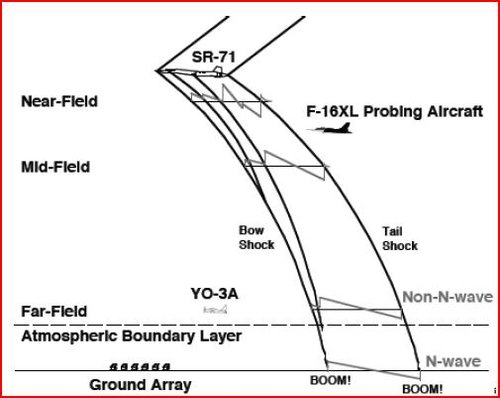
Since the completion of phaseⅡA, research and development in the sonic boom area has been concentrated in assimilating and applying the “near field ” sonic boom analysis technique developed by Carlson and Mclean of the NASA-Langley Laboratory. The work of Carlson and Mclean showed that, for an airplane of the length of the supersonic transport, the classic “near field” approach to sonic boom analysis represented an oversimplification of the sonic boom prediction, particularly in acceleration and climb. During this segment of the flight profile, the airplane is not at sufficiently low altitudes that it is not yet in the far-field.
Advanced near-field analysis technique became necessary in order to understand the true nature of the pressure waves emanating from the airplane. Near-field sonic boom analysis techniques shows significant differences in both the wave form and peak overpressure predicted for supersonic transport aircraft flying in the acceleration and climb-altitude region. In general, the peak overpressure, when accurately determined from near field theory, may be less than those anticipated from far-field consideration. Not only does the pose the problem of complete understanding and application of the near-field technique, but it also raises a second question as to shape changes in the airplane to maximize near-field effect. Study and analysis by near-field techniques revealed that changes in the total sonic-boom area progression with airplane length alter the near-field signature.
A total area progression following a three-halves power variation with length from the nose was found to produce a so-called “flat top” wave form which minimizes sonic-boom according to near-field theory. The principal part of the airplane that can be altered to vary sonic-boom area progression is the fuselage. Therefore, an extensive fuselage shape program was undertaken.
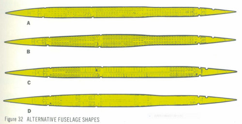
As shown in Figure 32, four different fuselage shapes were subjected to design study and wind-tunnel evaluation.

The first and third of these fuselages, designed “A” and ”C” in Figure 32, were basic five abreast seating, cylindrical fuselages, with area differences in the aft portions only. These variations have negligible effect on the near-field boom signature.

Fuselage “B” was developed to give a total sonic boom area progression following the optimum three-halves power relationship with length for a design Mach number of 1.8.
The additional area required in the forward region of fuselage “B” was obtained by increasing fuselage cross-section to six abreast.

Fuselage “D” represented another six abreast approach, but was aimed more at attaining a maximum length of six abreast seating than a three-halves power area distribution.

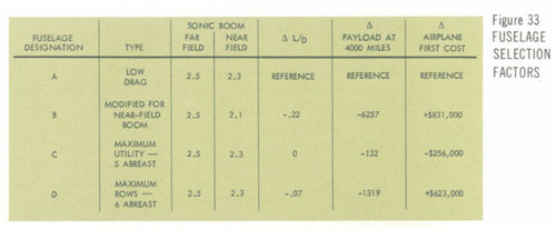
Complete design, wind tunnel, and cost analysis were performed on each of the four subject fuselage designs. Results of wind-tunnel model tests of all four fuselages in terms of supersonic maximum lift/drag ratio are shown in Figure 33.

Also shown in Figure 33, are weight-study results and manufacturing-cost estimates.

The drag and weight penalties associated with the “B” type fuselage were found to result in a very substantial payload loss as compared to fuselages of either type ”A” or type ”C”.

In addition, production cost of the ”B” type fuselage was substantially higher.

Since the ”C” type fuselage already achieved a good portion of the available near-field sonic boom reduction, and since its payload, cost factor, and interior arrangement flexibility factors were favorable, this fuselage was adopted for the L-2000-7 design.
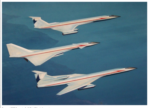
Last picture source
 

Attachments

  • L-2000-7 fuselage study.JPG
    L-2000-7 fuselage study.JPG
    123.6 KB · Views: 157
  • fuselage selection factor.JPG
    fuselage selection factor.JPG
    78.8 KB · Views: 138
  • sr71-boom-propagation-measurement.jpg
    sr71-boom-propagation-measurement.jpg
    24.2 KB · Views: 161
Last edited:
L-2000 wing surface structure was same as SR-71. (Source : Lockheed Horizons)
 

Attachments

  • SR-71 skin.JPG
    SR-71 skin.JPG
    66 KB · Views: 154
  • wing surface structure.JPG
    wing surface structure.JPG
    38.6 KB · Views: 109
  • wing skin.JPG
    wing skin.JPG
    70.2 KB · Views: 96
  • fuel tank structure.JPG
    fuel tank structure.JPG
    33.8 KB · Views: 126
Boeing 733, sorry if this has been posted before.
 

Attachments

  • lo;hioih.jpg
    lo;hioih.jpg
    239.3 KB · Views: 146
Thanks! It was a very beautiful dream that we almost got.

Lockheed was fully prepared to start production of the L-2000 based on SR-71's experience. But surprisingly they couldn't accept the order.
And they did not complain about the subsequent events and kept silent.Their attitude was admirable.

Please enjoy L-2000-7 fuel tanks development. (Source : as usual)
 

Attachments

  • Fuelltank.JPG
    Fuelltank.JPG
    57.6 KB · Views: 152
  • fuel tank model.JPG
    fuel tank model.JPG
    92.1 KB · Views: 112
  • fuel tank explanation.JPG
    fuel tank explanation.JPG
    57.7 KB · Views: 111
  • fuel tank testing.JPG
    fuel tank testing.JPG
    102.3 KB · Views: 145
Last edited:
Hi! Boeing 969-404 and 969-320.
Boeing selected the following three plans an alternative to the stalled 2707-200 SST.
1. 969-404 model
2. 969-302 model
3. 969-320 model

The 969-404 model was installed variable swept wing, with the engine back to the main wing.
The horizontal tail was said to design as not to suffer the exhaust gas flow in any state, but it is difficult to understand from the drawing.

The 969-302 type later became 2707-300 type SST with a larger wing area and number of seats.

The 969-320 model was designed based on NASA's SCAT-15F with retractable front wing.

969-404 and 969-320.jpg
 
Last edited:

Attachments

  • NAC-60.jpg
    NAC-60.jpg
    75.5 KB · Views: 164
  • NAC-60 (2).JPG
    NAC-60 (2).JPG
    52.7 KB · Views: 170
  • NAC-60 CABIN.jpg
    NAC-60 CABIN.jpg
    32.4 KB · Views: 164
  • 1964_Braniff_File_Photo_Charles_E_Beard_SST_Models.jpg
    1964_Braniff_File_Photo_Charles_E_Beard_SST_Models.jpg
    68.7 KB · Views: 159
  • NAC-60 PLAN VIEW.jpg
    NAC-60 PLAN VIEW.jpg
    79.1 KB · Views: 160
  • NAC-60 SPEC.jpg
    NAC-60 SPEC.jpg
    99.4 KB · Views: 180
NAA M-3000 SST.
 

Attachments

  • m3000_3.jpg
    m3000_3.jpg
    162.2 KB · Views: 185
  • m3000_r.jpg
    m3000_r.jpg
    312.4 KB · Views: 175
  • m3000c.jpg
    m3000c.jpg
    87 KB · Views: 197
Last edited:
These plan view shows early Douglas SST concept compared with Concorde. Upper one was SCAT-16 base design.(Justo-san and flateric-san's contribution)
Escanear0002.jpg
douglas632conceptsst.jpg
 
Last edited:
Little different concept.(boxkite-san's contribution)
 

Attachments

  • Douglas (SST-Entwurf mit T-Leitwerk)_JPG.jpg
    Douglas (SST-Entwurf mit T-Leitwerk)_JPG.jpg
    166.1 KB · Views: 197
  • Douglas 7.png
    Douglas 7.png
    483.5 KB · Views: 245
NAC-60 SST.JPG

I want to ask the moderator to devide this topic into each company's SST. For example Boeing, Lockheed, NAA, Douglas, Convair, Republic, Northrop, common,.........This topic become too big to check duplicate contribution.
 
Last edited:
Hello all
After so many years, I got a plastic model of Boeing 2707-200 SST ... Nice plane :D
(I´llpost some photos shortly when finished)
Since I met the F14 Tomcat during an airshow many years ago, I fell in love with sweeping wings
Well, I was an RC modeler when I was young and I thought it would be a great idea to build a RC flying one... (Maybe a big one ?!)
Any photos, drawings details etc... would help a lot if you have any. (Igot already a lot here)
See ya soon guys crazy_pilot-533c.gif
 
Last edited:
Oh wonderful staff.
Boeing B2707-100 with P&W JTF17 engine!!:oops:
Page 82 and 83 are important, because these pages explain the reason of design change.
969-404's horizontal tail stabilizer droop like a F-4 shape when cruise to avoid exhaust gas.
 

Attachments

  • 969-404 and 969-320.jpg
    969-404 and 969-320.jpg
    68.7 KB · Views: 158
  • droop tail.JPG
    droop tail.JPG
    45.3 KB · Views: 109
  • large tail.JPG
    large tail.JPG
    41.5 KB · Views: 109
Last edited:
A: Milled titanium panels (intrados).
B: Full rib (extrados) and milled plate (intrados).
C: Titanium sandwich (intrados and extrados).
D: Bonded titanium intrados coating.
E: Titanium coating in glued panels, except for train housing extrados panels.
F: Titanium construction with welded corrugated sheet (longitudinal members).
G: Titanium rib stiffened vertically.
H: Possible solution in brazed stainless steel honeycomb.

1: Front beam.
2: Rear beam.
3: Inner flap.
4: Brazed steel honeycomb structure.
5: Inner flaperon.
6: Outside flap.
7: Spoiler.
8: Outside flaperon.
9: Leading edge flap.
 

Attachments

  • Voilure couleur bleu.jpg
    Voilure couleur bleu.jpg
    216.6 KB · Views: 139
Last edited:
Thanks a lot to everyone, I continue seeking drawings and everything regarding the SST for the project.
Good drawing for the main landing gear and negative incidence of jets at the back of the plane...
I love the idea of swinging wings. I have seen a flying model of the F14 Tomcat at an airshow : Amazing!!!
Continue feeding the project ! :p:D:cool:

What is that project , please ? if you can talk about it.
Post 1141 above
I plan to build a R/C flying model of this plane probably 1/20 (?)
 
'Evening Gents.
On this 733-197 plan ( posted already on post 1073 ), could someone please tell me what "LEMAC" and "MAC" stands for ?
Is "MAC" the cord (64 ft 6 in) of the wing at the sweep wing pivot position ?
19267709688_aef6de6e89_3k.jpg
 
'Evening Gents.
On this 733-197 plan ( posted already on post 1073 ), could someone please tell me what "LEMAC" and "MAC" stands for ?
Is "MAC" the cord (64 ft 6 in) of the wing at the sweep wing pivot position ?
View attachment 622935

MAC = "mean aerodynamic chord"
LEMAC = "leading edge of mean aerodynamic chord"
 
Yes this subsonic liner is not 747.
Lockheed said this is 747 in this picture, but it's C-5.:rolleyes:
 

Attachments

  • キャプチャ.JPG
    キャプチャ.JPG
    49.3 KB · Views: 96
Last edited:

Attachments

  • Box detail.jpg
    Box detail.jpg
    49.8 KB · Views: 96
  • Box Lid.jpg
    Box Lid.jpg
    31.8 KB · Views: 87
  • toy airliner.jpg
    toy airliner.jpg
    34.4 KB · Views: 95
  • toy airliner 2.jpg
    toy airliner 2.jpg
    33.3 KB · Views: 93
  • toy airliner.jpg
    toy airliner.jpg
    34.4 KB · Views: 93
  • toy airliner 2.jpg
    toy airliner 2.jpg
    33.3 KB · Views: 98
Er yes, sorry, did it on my phone and the eyesight suffers after beer, could it be moved to the right place?
 
Back
Top Bottom