I think accomplishing that requires a fairly exacting ESM system and AESA. The more precise the bearing and azimuth, the tighter the search. And a mechanical search seems problematic- if nothing else, a mechanical antenna will illuminate a much wider arc, particularly considering side lobes. I assume it can be done in principle but I think the F-22 was the first to make this truly practical and automated.

You are using an out of date browser. It may not display this or other websites correctly.
You should upgrade or use an alternative browser.
You should upgrade or use an alternative browser.
Sukhoi Su-57 flight testing and development
- Thread starter overscan (PaulMM)
- Start date

Acatomic
ACCESS: Secret
- Joined
- 18 October 2020
- Messages
- 300
- Reaction score
- 861
You are talking about djcross? I think he only worked on F-22.Considering the detailed changes between Phase 1 and Phase 2 frames (note the main weaponbay doors for instance) they have good understanding of the details and where they are worth it. According to the now chief engineer of the project, T-50 exceeded the stealth requirements. And someone who has worked on the stealth of F-22 and F-35 claimed T-50 is "metal marble class". Personally i dont think T-50 is as stealthy as F-22 - but i think it is stealthier than what most people give it credit for being.All the evidence points to a basic airframe configuration optimised for low RCS from the front only, with lesser regard for other angles.
The existing Su-57 airframes don't show the attention to detail needed for a truly low (VLO) RCS. We have no idea what the requirement was however - presumably it meets the requirements in the area.
He did have a interesting comment about it in 2018:
I have never seen an official document which states the design rationale for SU-57 low observables.
I can speculate that the SU-57 design provides an X-band detection advantage over western Gen 4 fighters. SU-57 edge alignment and RAM treatments likely provide effective X-band RCS reduction. This gives SU-57 first shot/A-pol advantage against Gen 4 fighters which would guard high value targets such as AWACS. NATO relies on AWACS directed Gen 4 fighters for air defense. Without the Air Battle Management coordination of fighters and long range L-band sensor capabilities of AWACS, NATO is vulnerable to air attack.
NATO has no effective SAM defenses, so SU-57 does not need RCS treatments to protect against S-band SAMs. SU-57 does not appear to possess S-band RAS features which some western fighters possess.
This speculative design philosophy is radically different that F-22 and F-35, where RCS was intended to counter the vast proliferation of Russian SAMs which would otherwise inhibit operation inside the IADS.
https://www.key.aero/comment/1968980#comment-1968980

Acatomic
ACCESS: Secret
- Joined
- 18 October 2020
- Messages
- 300
- Reaction score
- 861
One interesting tidbit from last year's Airbus LOUT presentation.
https://www.secretprojects.co.uk/threads/airbus-low-observable-uav-testbed-lout.32598/
Can you spot the Felon? (Higher res. in pdf file)

https://www.secretprojects.co.uk/threads/airbus-low-observable-uav-testbed-lout.32598/
Can you spot the Felon?
(Higher res. in pdf file)
Attachments
- Joined
- 11 February 2010
- Messages
- 1,719
- Reaction score
- 3,181
Looking at the background behind Su-57 model, i guess they're using PCSR and their result might be similiar with Air Power Australia's Assessment

flanker
ACCESS: Top Secret
- Joined
- 20 March 2008
- Messages
- 936
- Reaction score
- 261
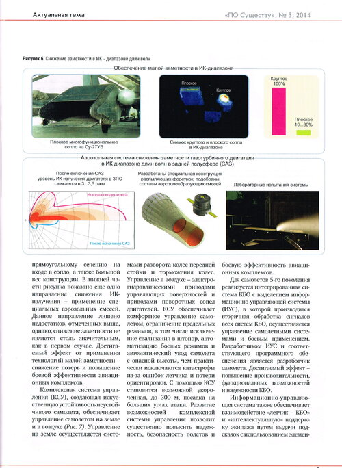
I haven't noticed it previously, but the KNS exhaust has perforations around the edge of the exhaust... Wonder if it is a similar system to YF-23's. Probably a better explanation but still curious, maybe others can chime in. There is another IR supression system on T-50 and it is basically aerosol dumping into the exhaust.
Attachments
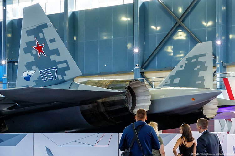
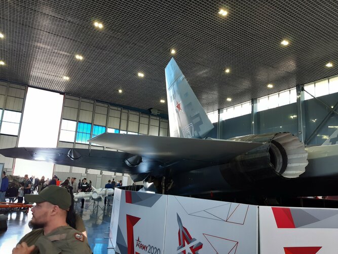
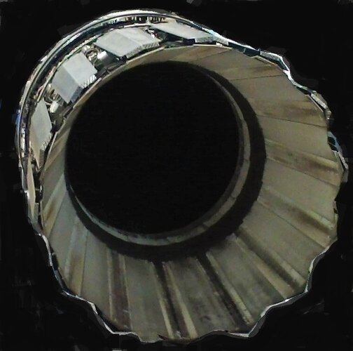
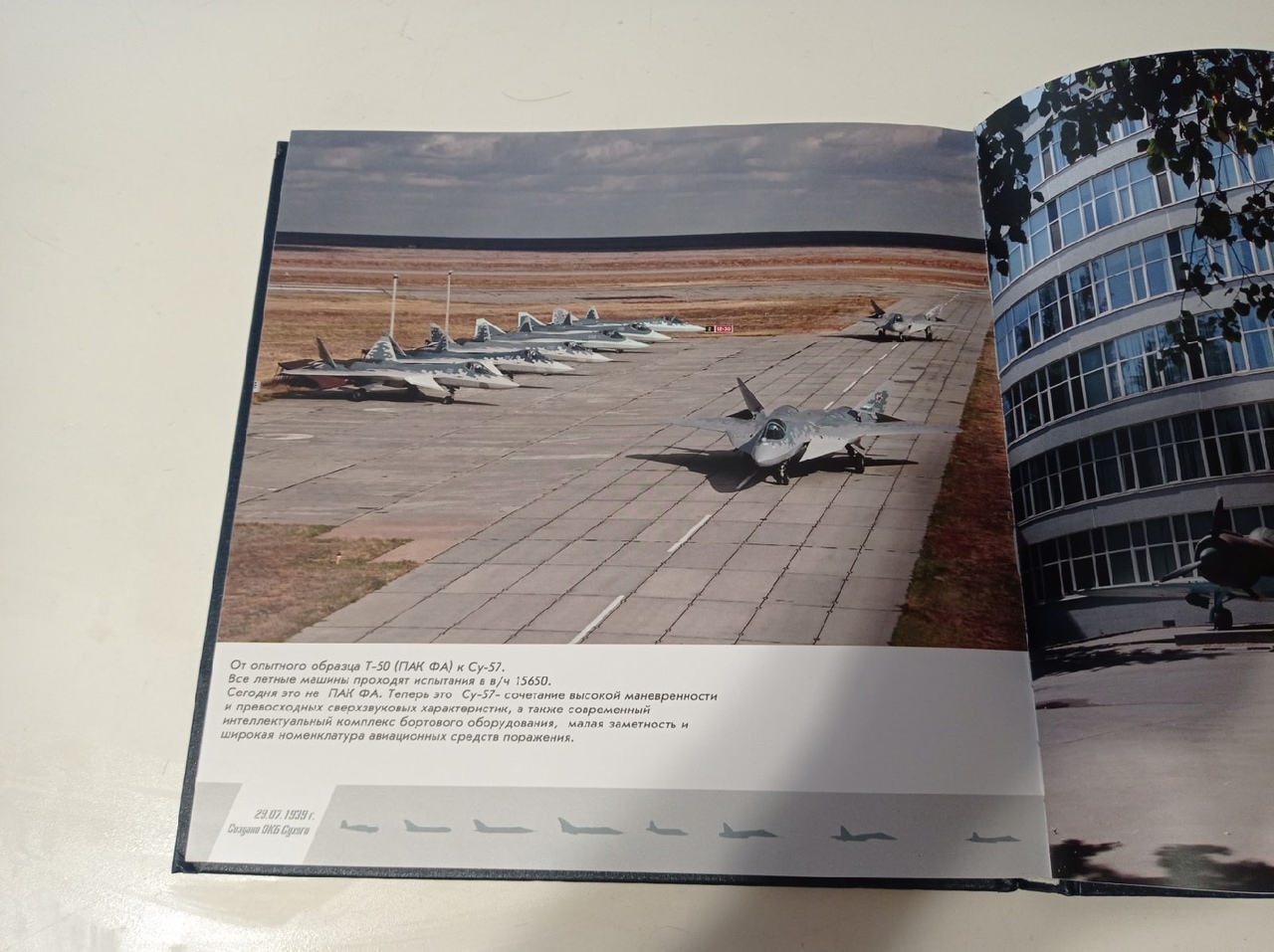
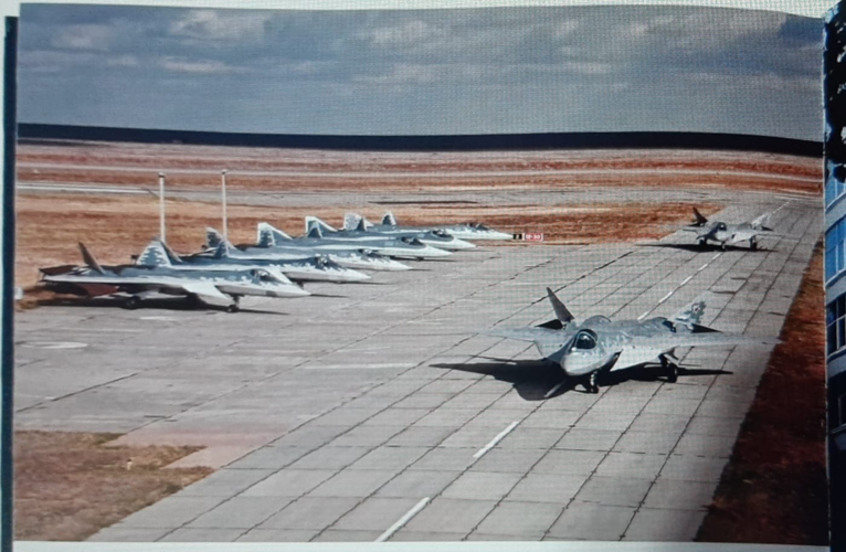
Su-57 in Akhtubinsk, from the jubilee edition "80 years of Sukhoi Design Bureau".
Last edited by a moderator:
Cannonfodder43
ACCESS: Confidential
- Joined
- 8 December 2019
- Messages
- 127
- Reaction score
- 360
I apologize if I did not look hard enough but what is this Aerosol Injection system that many talk about? I presume its some sort of IR signature suppression system but how would it work?
Your guess is as good as anybody else's in the public domain - the rather brief blurb posted by flanker represents the sum total of all information that is available, AFAIK. Based on the drawing, the idea is to create a sheath of aerosol-doped air around the nozzle and exhaust plume which is IR-opaque thanks to the properties of the substance.
Cannonfodder43
ACCESS: Confidential
- Joined
- 8 December 2019
- Messages
- 127
- Reaction score
- 360
Seems rather counterproductive to have to carry an aerosol supply in order to reduce IR plume visibility. Extra weight and complexity that could rather be dealt with by the F-35 like bypass air flow around nozzle.
Unless that measure only works with the lower cruising speed and higher BPR of the F135 and such.
Or that aerosol works well enough to warrant its adoption.
Unless that measure only works with the lower cruising speed and higher BPR of the F135 and such.
Or that aerosol works well enough to warrant its adoption.
- Joined
- 11 February 2010
- Messages
- 1,719
- Reaction score
- 3,181
The nozzle serration is supposed to promote mixing between hot engine exhaust and the cooler ambient air. This reduces the amount of plume emmission coming from the engine. The aerosol takes the game bit further by "actively" cools the exhaust down to the point where its temperature would emit wavelength which be one strongly absorbed by ambient air.

For example. In 10000 meter altitude. If one desires to reduce the detectability of the engine or other infra red emmission he has to "cool" the emmission to the wavelength which have 0 transmittance. Means that the infra red energy emitted on that wavelength would be strongly absorbed by atmosphere. As seen at above chart from MODTRAN web app. One would wish to cool its engine emmission to about 6 micron wavelength or 9 micron or down to 14 micron. These wavelengths correspond to temperatures of 756, 595 and 480 Degrees Celcius. Typical Jet engine exhaust temperature is about 900 K or about 1173 Degrees Celcius.
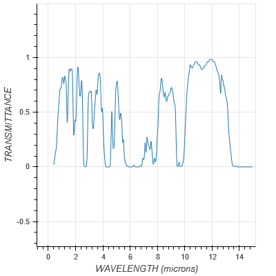
For example. In 10000 meter altitude. If one desires to reduce the detectability of the engine or other infra red emmission he has to "cool" the emmission to the wavelength which have 0 transmittance. Means that the infra red energy emitted on that wavelength would be strongly absorbed by atmosphere. As seen at above chart from MODTRAN web app. One would wish to cool its engine emmission to about 6 micron wavelength or 9 micron or down to 14 micron. These wavelengths correspond to temperatures of 756, 595 and 480 Degrees Celcius. Typical Jet engine exhaust temperature is about 900 K or about 1173 Degrees Celcius.
sound like a great solution, but how much aerosol in weight you need to carry to cool the engine that much though?The nozzle serration is supposed to promote mixing between hot engine exhaust and the cooler ambient air. This reduces the amount of plume emmission coming from the engine. The aerosol takes the game bit further by "actively" cools the exhaust down to the point where its temperature would emit wavelength which be one strongly absorbed by ambient air.
View attachment 645014
For example. In 10000 meter altitude. If one desires to reduce the detectability of the engine or other infra red emmission he has to "cool" the emmission to the wavelength which have 0 transmittance. Means that the infra red energy emitted on that wavelength would be strongly absorbed by atmosphere. As seen at above chart from MODTRAN web app. One would wish to cool its engine emmission to about 6 micron wavelength or 9 micron or down to 14 micron. These wavelengths correspond to temperatures of 756, 595 and 480 Degrees Celcius. Typical Jet engine exhaust temperature is about 900 K or about 1173 Degrees Celcius.
Is it better if aerosol is something that can block Infrared radiation ?

Grey Havoc
ACCESS: USAP
- Joined
- 9 October 2009
- Messages
- 24,500
- Reaction score
- 18,175
Some form of thermoelectric cooling might be a possibility. Maybe combined with a gas/solid heat sink or something even more exotic?

- Joined
- 2 January 2006
- Messages
- 4,236
- Reaction score
- 8,283
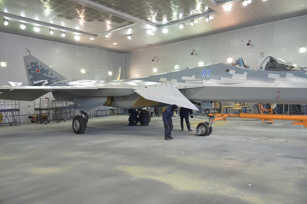
First serial:
But is this the one that crashed or in fact no. 02 renumbered to 01?
Last edited by a moderator:

haavarla
ACCESS: Secret
- Joined
- 29 June 2010
- Messages
- 200
- Reaction score
- 255
You would think they went the extra mile and re-numbered the side Bort Numbers. No need to be reminded of that crash every day, right?
But is this the one that crashed or in fact no. 02 renumbered to 01?
Last edited by a moderator:
Original 01First serial:
But is this the one that crashed or in fact no. 02 renumbered to 01?
Last edited by a moderator:

ArihantRoy93
ACCESS: Restricted
- Joined
- 20 September 2020
- Messages
- 41
- Reaction score
- 48
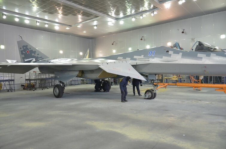
Sukhoi OKB hasn't applied RAM coatings on the entire wet surface of the Felon. The surface may itself act as a radar absorbent structure due to the inclusion of some exotic stuff .
In here we see a thick ram layer around the gun port and cooling covers which extends right upto the radome .around the KS-U aperture just beneath the cockpit .
Is this the equivalent of boundary type magentic ferrite ram treatments we have seen in F-35? There are two small pitot tubes portruding from the sides.
In here we see a thick ram layer around the gun port and cooling covers which extends right upto the radome .around the KS-U aperture just beneath the cockpit .
Is this the equivalent of boundary type magentic ferrite ram treatments we have seen in F-35? There are two small pitot tubes portruding from the sides.
Last edited by a moderator:
flanker
ACCESS: Top Secret
- Joined
- 20 March 2008
- Messages
- 936
- Reaction score
- 261
Source;
View: https://twitter.com/FelonFrazor/status/1334907137177292800/photo/1
Highest resolution available attached.
Highest resolution available attached.
Attachments
Samoderzhets
ACCESS: Restricted
- Joined
- 7 August 2017
- Messages
- 8
- Reaction score
- 31
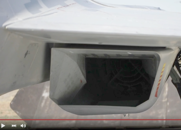
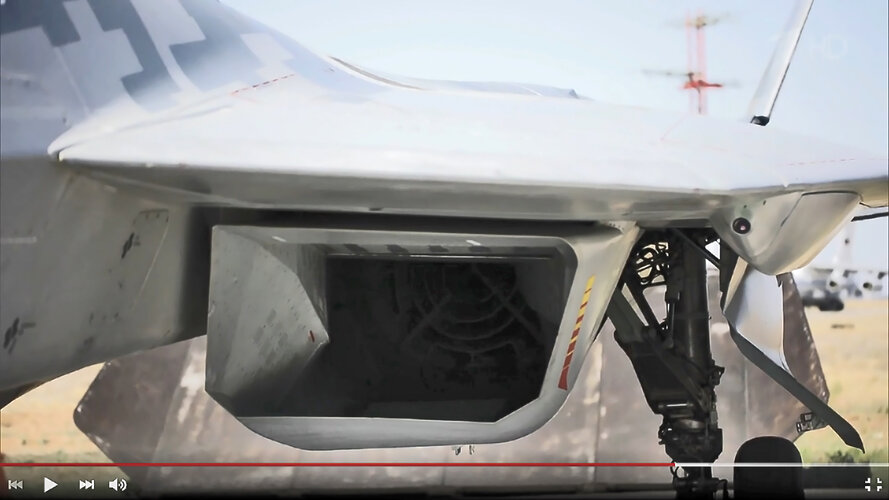
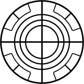
People appear to have missed the first glimpse at the actual radar blocker. I guess most of you watched the video in question (https://www.1tv.ru/shows/chasovoy/vypuski/glic-100-let-na-krylyah-chasovoy-vypusk-ot-18-10-2020) on youtube, where compression kills crucial details. I decided to check the footage at the source and here it is:
Here is the patent and fig. 3 certainly looks familiar, altough there are interesting differences.
https://findpatent.ru/patent/262/2623031.html

Here is the patent and fig. 3 certainly looks familiar, altough there are interesting differences.
https://findpatent.ru/patent/262/2623031.html
- Joined
- 2 January 2006
- Messages
- 4,236
- Reaction score
- 8,283
People appear to have missed the first glimpse at the actual radar blocker. I guess most of you watched the video in question (https://www.1tv.ru/shows/chasovoy/vypuski/glic-100-let-na-krylyah-chasovoy-vypusk-ot-18-10-2020) on youtube, where compression kills crucial details. I decided to check the footage at the source and here it is:
Here is the patent and fig. 3 certainly looks familiar, altough there are interesting differences.
https://findpatent.ru/patent/262/2623031.html
Indeed interesting!

QuadroFX
Russia, Chelyabinsk


- Joined
- 27 December 2005
- Messages
- 19,226
- Reaction score
- 35,645
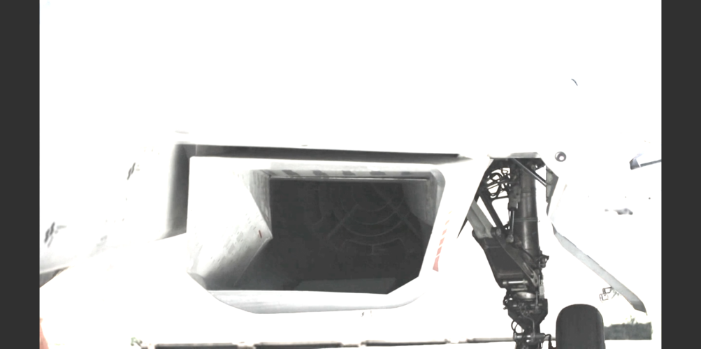
If I understand the patent correctly rather the device is of some length and the visible part is the leading edge and its purpose is to introduce multiple bounces into the radar path to and from the engine face to attenuate the signal. By reducing the duct into multiple smaller sections the number of bounces is greatly increased.

- Joined
- 2 August 2006
- Messages
- 3,335
- Reaction score
- 1,847
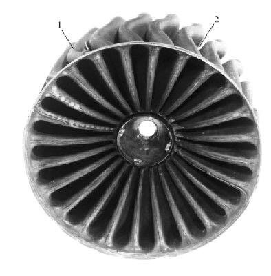
It would actually function as both, just due to the nature of the flow going through the blocker. The problem is, you can only see the front face of it. You can almost see some curvature in the wall of the small section at the bottom, the sort of miniature s-duct forming. I was actually more interested in the fixed oblique ramps that are in the sides of the inlets now.That's a weird one. Looks more like a device for flow control rather than a blocker.
- Joined
- 11 February 2010
- Messages
- 1,719
- Reaction score
- 3,181
Guess the "real" blocker is behind it. Or maybe that's where the blocker would be attached, ahead of it. The blocker would be at front while that device "straighten" any flow distortion caused by the blocker to provide the engine the air it needs.
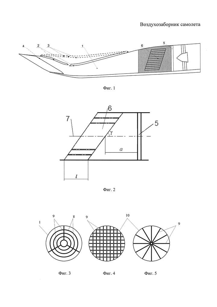
Or maybe yes it's the blocker itself, consulting from this patent image
Or maybe yes it's the blocker itself, consulting from this patent image

TSARb
ACCESS: Confidential
- Joined
- 8 March 2011
- Messages
- 122
- Reaction score
- 324
This is the blocker of the next engine called "product 30".why does it look different from this: I thought this is the blocker?
View attachment 645600
And not the real one, but close enough actually.
I see them as faceted DSI bumpsI was actually more interested in the fixed oblique ramps that are in the sides of the inlets now
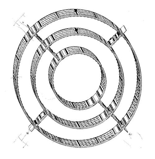
You were misleaded. Here is a schematic view of PAK FA radar-blocker that was published many years ago. Looks pretty similar to the recent photo, right?why does it look different from this: I thought this is the blocker?
View attachment 645600
Attachments
Similar threads
-
 Sukhoi Su-57 / T-50 / PAK FA first flight - pictures, videos and analysis [2010]
- Started by flateric
- Replies: 872
-
 Sukhoi Su-57 / T-50 / PAK FA - flight testing and development Part I [2010-2012]
- Started by Matej
- Replies: 760
-
-
 Sukhoi PAK FA news and speculation (T-50, I-21) Part I [2006-2008]
- Started by overscan (PaulMM)
- Replies: 455
-