boxkite said:
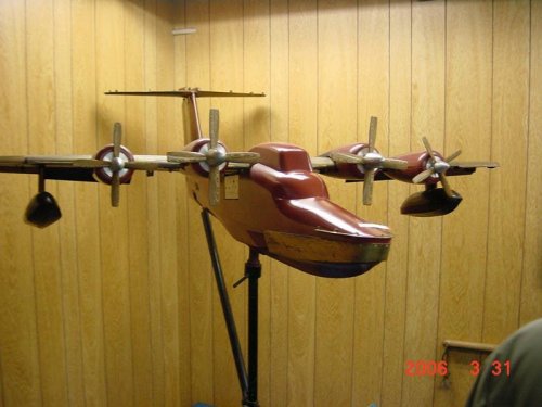
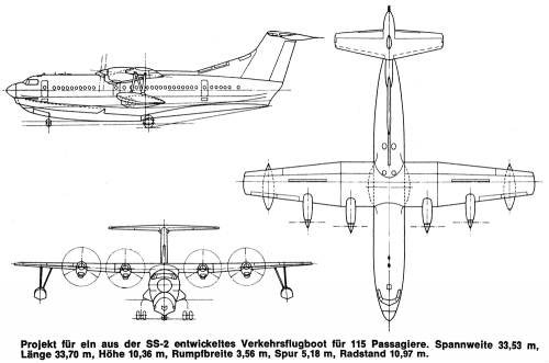
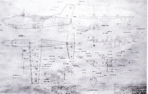
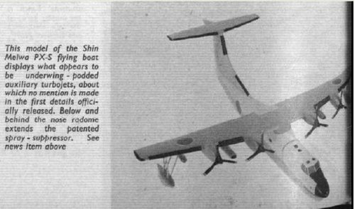
Is this an aid(ing) air intake on the back of the fuselage (in front of the wings)?
Boxkite,
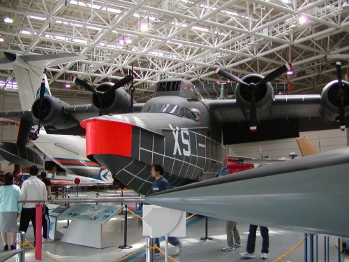
On the UF-XS, the twin T58s supplied compressed air for boundary layer control (see below). But I do not think that your sketch shows the UF-XS.
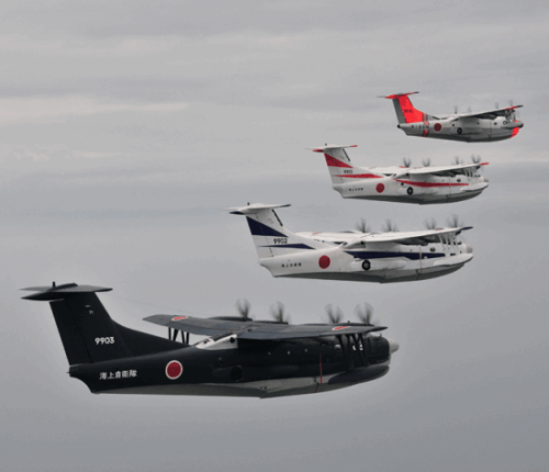
The proportions are wrong even for that much-modified Albatross. I suspect that you were on the right track suggesting that this was an early view of the PS-1. Probably, an artist extrapolated from the UF-XS (which was flying by 1962) to envision the then-future ASW boat.
----------
from "Giant Amphibian" by Tim Wright, Air & Space magazine, Dec 2003
http://www.airspacemag.com/issues/2003/december-january/cit-wright.php?page=1
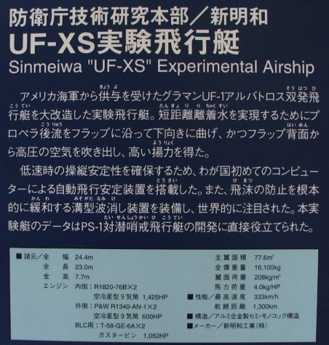
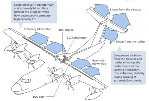
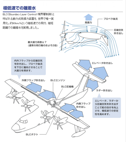
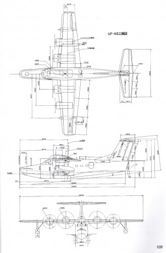
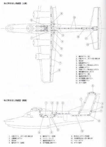
ShinMaywa experimented with an array of high-lift devices to enable the UF-XS to take off and land at slower speeds. The tailplane and outer sections of the wings had leading edge slats. Flaps on the inner sections of the wings’ trailing edges could be deflected as much as 80 degrees, and on the outer sections, as much as 60 degrees. Engineers augmented these movable surfaces with an experimental system for controlling the boundary layer...
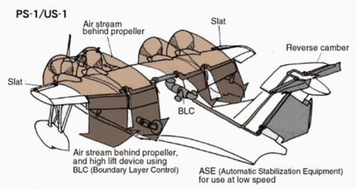
As an aircraft approaches the low speeds associated with landing, the boundary layer flowing over the wing becomes increasingly turbulent and the wing loses lift. To retain smooth flow, and therefore lift, as long as possible at slower speeds, ShinMaywa devised a system to blow air over the flaps and the elevator to keep the airflow smooth, enabling the aircraft to maintain lift and control at low speed. The air was produced by a 1,250-hp General Electric T58 turboshaft engine mounted in the aircraft cabin.
The UF-XS research showed that aircraft with such a system for boundary layer control (BLC) - as well as improved hull designs - could operate in much rougher seas than had been possible before. ShinMaywa incorporated the high-lift devices developed for the research program into the design of the anti-submarine PS-1 and the US-1/US-1A rescue aircraft.
-------


 .
.