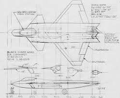
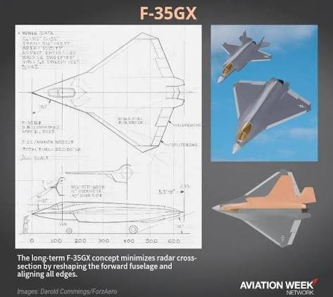
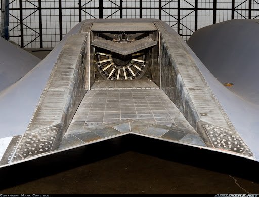
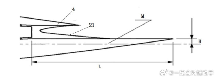
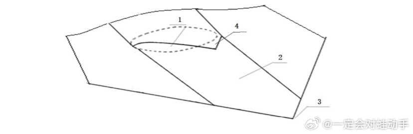
May be the nozzle design patent for the first prototype.
An aero-engine nozzle with adjustable detectability
1. With the continuous advancement of aerospace detection technology, detectability management of aircraft in complex airspace environments has become a key focus of frontier research. The nozzle system of an aero-engine, as a critical passage for discharging high-temperature combustion gases, produces significant electromagnetic scattering characteristics and infrared radiation signatures, and is one of the main factors affecting the aft signature characteristics of an aircraft. Therefore, developing advanced nozzle technologies to effectively manage these signature characteristics is of great significance for improving the overall performance indices of aircraft.
2. At present, the design of aero-engine nozzles faces an inherent contradiction between high-performance aerodynamic requirements and low-detectability requirements. High-performance aero-engines pursue a high thrust-to-weight ratio and high efficiency, which require the nozzle to have a smooth flow path and optimized area-adjustment capability under full-power, i.e., afterburning, conditions so as to maximize thrust output. However, from the perspective of low detectability, it is necessary to optimize signature characteristics by means such as “geometric shaping” and “thermal management,” which often requires changing or even constraining the shape of the flow path, thereby possibly disturbing airflow and causing performance losses. How to achieve low detectability without sacrificing core aerodynamic performance is an extremely challenging design problem.
3. Among existing technical solutions, there are certain limitations in the approaches for achieving low detectability of nozzles. The first is conventional mechanically adjustable nozzle technology. The design core of such nozzles lies in changing the throat area through movement of movable adjusting flaps, so as to meet the aerodynamic requirements of the engine under different operating conditions. However, the original purpose of their adjustment mode is entirely to serve aerodynamic performance, and the range of configuration variation does not take low detectability as a design objective. Therefore, their structure cannot effectively shield upstream high-temperature components, and has limited potential in reducing electromagnetic and infrared signature characteristics.
4. The second is fixed special-configuration nozzle technology, such as nozzles employing curved flow paths or non-axisymmetric cross sections. By virtue of their inherent geometry, such designs can physically shield internal high-temperature regions by the nozzle walls, thereby optimizing signature characteristics to a certain extent. However, such nozzles are generally of fixed configuration and lack throat-area adjustment capability. When an aircraft needs to ignite an afterburner to obtain maximum thrust, the fixed and complex flow-path shape restricts exhaust efficiency, resulting in significant thrust-performance losses, and making it difficult to meet the stringent thrust-response requirements of highly maneuverable flight platforms. Therefore, they are commonly used in application scenarios that do not require a wide thrust-variation range.
5. The third is that, in terms of thermal management technology, existing nozzles mostly rely on cold air from an engine bypass duct or airframe bleed air to perform continuous wall cooling. This long-duration and stable cooling mode has a basic effect in maintaining component temperatures and achieving basic infrared signature control. However, when an aircraft faces specific high-demand scenarios requiring abrupt changes in signature characteristics, such as in heavily monitored airspace or when urgent flight-state adjustment is required, the cooling intensity and response speed of the prior art cannot achieve rapid and active suppression of signature characteristics, and there is a bottleneck in improving effectiveness.
6. In summary, the prior art lacks a comprehensive nozzle solution capable of intelligently adapting to multiple flight-mission requirements. In particular, for high-performance afterburning engines, there is an urgent need for an advanced nozzle capable of dynamically adjusting its own configuration and flexibly switching between a “high aerodynamic performance mode” and a “low-detectability mode.” Such a nozzle must not only solve the integrated-design problem of variable geometry and signature control, but also integrate a highly reliable adjustment mechanism, effective sealing, and a multi-stage thermal management system within a compact space, thereby truly achieving synergistic optimization of aerodynamic performance and low detectability, and enhancing the overall technical competitiveness of the aircraft.
Technical Solution
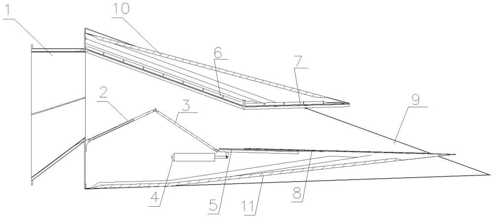
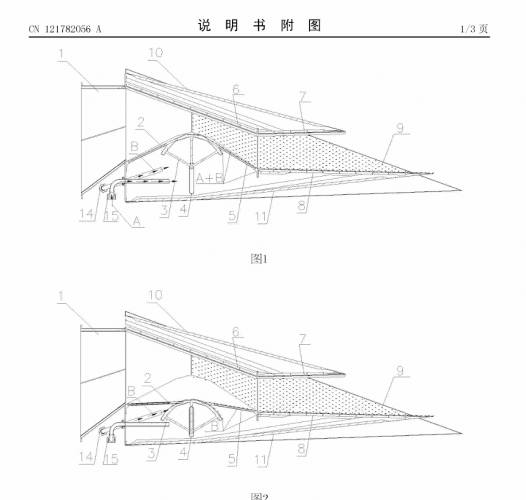
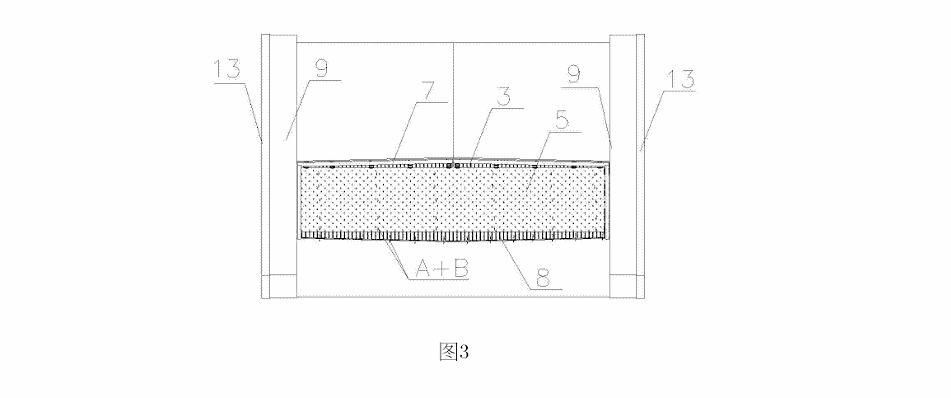
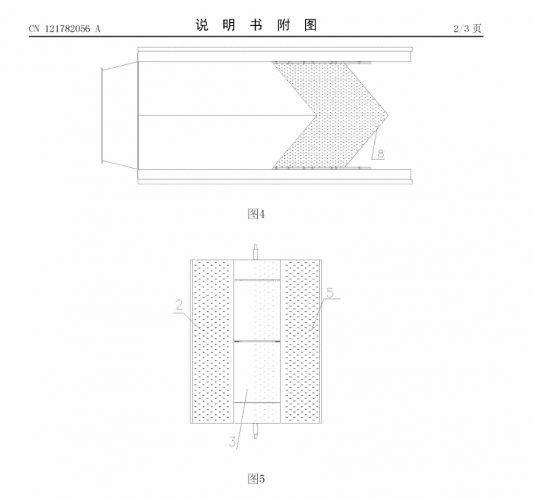
1. To solve the above problems, the present application provides a detectability-adjustable aero-engine nozzle, mainly comprising a rectangular section connected to a circular nozzle outlet through a round-to-square transition section. The rectangular section includes an upper outer cowl, a lower outer cowl, and side walls. An adjusting plate is disposed between the upper outer cowl and the lower outer cowl. The adjusting plate includes a first adjusting flap, a second adjusting flap, and a unilateral expansion section. The first adjusting flap and the second adjusting flap are respectively slidably disposed in track slots of an arcuate throat plate. The other end of the first adjusting flap is hinged to the round-to-square transition section. The other end of the second adjusting flap is hinged to the unilateral expansion section. The other end of the unilateral expansion section is connected to a distal end of the lower outer cowl. The arcuate throat plate is mounted by side shafts in tracks located on the side walls, and is driven by an actuator cylinder to move upward and downward, so as to control a throat clearance between the adjusting plate and the upper outer cowl.
2. A gas accommodation space is formed between the adjusting plate and the lower outer cowl. Gas drawn from an engine bypass duct or an engine nacelle enters the gas accommodation space through a first injection rod. A cooling medium drawn from an ultra-low-temperature cold source enters the gas accommodation space on demand through a second injection rod. Film cooling holes are provided at least on the unilateral expansion section of the adjusting plate, so as to introduce the gas in the gas accommodation space to an inner wall of the rectangular section to form a cooling air film.
3. Preferably, an arcuate surface of the arcuate throat plate has track slots, and two ends of the track slots are provided with tenon grooves for mounting tenons of the first adjusting flap and the second adjusting flap.
4. Preferably, an inner side of the upper outer cowl is further provided with an upper convergent flap configured to contract a vertical spacing of the rectangular section, and an upper divergent flap configured to expand the vertical spacing of the rectangular section. The upper convergent flap and the upper divergent flap are opposite, at a connection portion thereof, to a hinged end between the second adjusting flap and the unilateral expansion section.
5. Preferably, film cooling holes are respectively provided on the second adjusting flap, the upper divergent flap, the side walls, and the arcuate throat plate.
6. Preferably, the ultra-low-temperature cold source is liquid nitrogen.
7. Preferably, in an emergency evasion state, the second injection rod is briefly opened to rapidly cool the nozzle by the cooling medium.
8. Through a deformable nozzle structure, the present application realizes intelligent switching between high aerodynamic performance and low detectability, and innovatively integrates long-duration and short-duration active cooling technologies, ultimately achieving ultra-high-performance comprehensive signature management.
Technical Features
1. A detectability-adjustable aero-engine nozzle, comprising a rectangular section connected to a circular nozzle outlet through a round-to-square transition section (1), wherein the rectangular section comprises an upper outer cowl (10), a lower outer cowl (11), and side walls (9), characterized in that an adjusting plate is disposed between the upper outer cowl (10) and the lower outer cowl (11); the adjusting plate comprises a first adjusting flap (2), a second adjusting flap (5), and a unilateral expansion section (8); the first adjusting flap (2) and the second adjusting flap (5) are respectively slidably disposed in track slots of an arcuate throat plate (3); the other end of the first adjusting flap (2) is hinged to the round-to-square transition section (1); the other end of the second adjusting flap (5) is hinged to the unilateral expansion section (8); the other end of the unilateral expansion section (8) is connected to a distal end of the lower outer cowl (11); the arcuate throat plate (3) is mounted by side shafts in tracks (4) located on the side walls (9), and is driven by an actuator cylinder to move upward and downward, so as to control a throat clearance between the adjusting plate and the upper outer cowl (10).
2. The detectability-adjustable aero-engine nozzle according to claim 1, characterized in that an arcuate surface of the arcuate throat plate (3) is provided with track slots, and two ends of the track slots are provided with tenon grooves for mounting tenons of the first adjusting flap (2) and the second adjusting flap (5).
3. The detectability-adjustable aero-engine nozzle according to claim 1, characterized in that an inner side of the upper outer cowl (10) is further provided with an upper convergent flap (6) configured to contract a vertical spacing of the rectangular section, and an upper divergent flap (7) configured to expand the vertical spacing of the rectangular section; the upper convergent flap (6) and the upper divergent flap (7) are arranged such that a connection portion thereof faces a hinged end between the second adjusting flap (5) and the unilateral expansion section (8).
4. The detectability-adjustable aero-engine nozzle according to claim 3, characterized in that film cooling holes are respectively provided on the second adjusting flap (5), the upper divergent flap (7), the side walls (9), and the arcuate throat plate (3).
5. The detectability-adjustable aero-engine nozzle according to claim 1, characterized in that the ultra-low-temperature cold source is liquid nitrogen.
6. The detectability-adjustable aero-engine nozzle according to claim 1, characterized in that, in an emergency evasion state, the second injection rod (15) is briefly opened to rapidly cool the nozzle by a cooling medium.
Technical Summary
The present application belongs to the technical field of aero-engine structural design, and relates to a detectability-adjustable aero-engine nozzle. The core of the nozzle lies in a deformable structure, which mainly comprises a round-to-square transition section, adjusting flaps, an arcuate throat plate, a unilateral expansion section, and an actuating mechanism. The arcuate throat plate is driven by an actuator cylinder to move upward and downward in tracks on the side walls, thereby driving the adjusting flaps to move, so as to intelligently switch the nozzle configuration: upward movement forms a low-detectability mode, in which the unilateral expansion section achieves full shielding; downward movement enables a high-thrust mode. Meanwhile, the nozzle integrates a dual-path cooling system, one path providing long-duration basic cooling, and the other path being capable of briefly injecting an ultra-low-temperature medium for active intensive cooling. The engine of the present application can meet detection-avoidance requirements, as well as requirements for flame propagation and stability in an afterburning state.
Inventors: Wang Dianlei, Liu Taiqiu, Zhao Ming, Cheng Jia, Wu Fei, Zhan Jiazhe
Protected technology user: AECC Shenyang Engine Research Institute
Technology development date:
Technology publication date: April 2, 2026