LM Ericsson were given responsibility to develop the new PS-05/A radar for the Gripen. Ericsson have a long history of radar development, beginning in 1950 with cooperation and license production of a Thomson-CSF radar from 1950 for the Lansen, development of PS-01/A and PS-03/A indigenous pulse radar for the Draken, PS-37 solid-state pulse radar for the AJ-37 Viggen, then the first operational operational pulse-doppler radar in Europe, the PS-46/A for the JA-37 Viggen.
From 1981 Ericcson collaborated extensively with Ferranti (later GEC Marconi), who were working on the similar Blue Vixen radar. Ericsson's D80 computer was adopted on the Blue Vixen, while Blue Vixen's antenna platform and drive were used on the PS-05/A.
The first PS-05/A test radar was flown from 1987 in a Viggen. The first production standard radar flew in 1989, and testing was completed in 1993.
The PS-05/A radar is software driven, allowing new modes to be incorporated relatively easily.
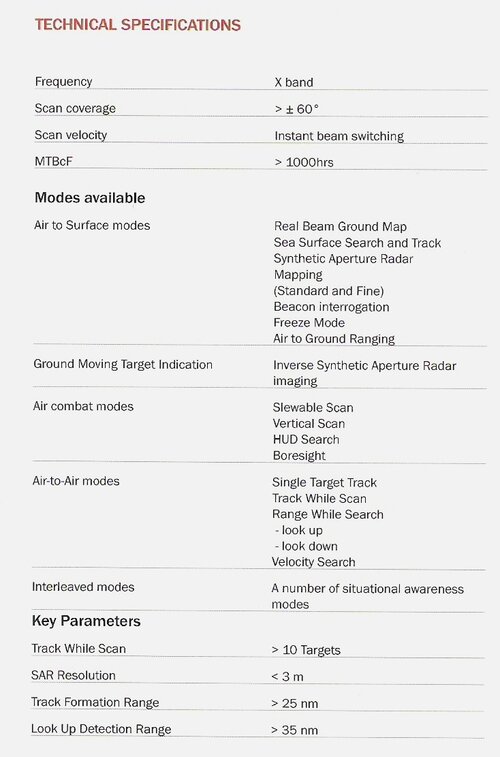
Basic modes
Air-to-air using high PRF and medium PRF waveforms.
Long-range search
multiple-target track-while-scan
multiple priority target tracking
short-range, wide-angle search and track for air combat
high-resolution single-target tracking
raid assessment
Air-to-ground
search
tracking
high resolution mapping
air-to-surface ranging
The main waveforms generated are
HPD - a high PRF, pulse-doppler mode for use against airborne approaching targets
MPD - a medium PRF pulse-doppler mode for use against approaching and receding targets- a special high resolution sub-mode is designed for target tracking
LPD - a mode using Doppler processing designed for use against surface targets
LPRF - a low-PRF mode with pulse-to-pulse frequency agility for use against surface targets and for real-beam mapping
AGR - a mode exclusively designed for ground target ranging
DBS - Doppler Beam Sharpening mode utilising Doppler processing for high resolution mapping, with high-angular coverage obtained by continuous antenna scanning
SLM (SpotLight Mode) - an SAR mode utilising Doppler processing for very high-resolution mapping.
The PS-05/A radar comprises six Line-Replaceable Units (LRUs):
Antenna Unit: lightweight 600 mm diameter low sidelobe monopulse planar array, with guard channel antenna, IFF dipoles and digital servo control, weighing 25 kg
Power Amplifier Unit and Transmitter Auxiliary Unit: 1kW average power, flexible waveform, liquid cooled, TWT
system. These two LRUs weigh 73 kg altogether
High-Frequency Unit: multiple channel receiver, monopulse design, pulse-to-pulse frequency-agile, microwave integrated circuit
design, internally software controlled, 32 kg in weight
Signal and Data Processor: Ericcson D-80 processor, employing ASIC technology, hardware optimised for programming in Pascal, weighing 23 kg
Waveguide unit (2kg?)
Sources
Jane's Avionics 2002
Gerard Keijsper, Saab Gripen: Sweden's 21st Century Multi-role Aircraft Aerofax, 2003
Kinghorn et al, The Blue Vixen Radar for Sea Harrier FRS.2 GEC Review Vol 9 No 3 1994
In other words the PS-05/A is a good modern flat-plate puse doppler multimode radar like all the others in the world - they even all look the same now: Israeli EL/M 3032; Eurofighter Captor; Mirage 2000 RDY; APGs 70, 65, 73 ....; Phazotron Zhuk; NIIP's N-011.
takes all the fun out of it. I preferred it when everyone's radars looked different and you could have lots of working out "... now why did they do it that way?"
In one sense, you are completely correct. However, once you bring the JAS-39's datalink capabilities into play, things look a little different.
From Bill Sweetman's article for JEDOnline;
The TIDLS can connect up to four aircraft in a full-time two-way link. It has a range of 500 km and is highly resistant to jamming; almost the only way to jam the system is to position a jammer aircraft directly between the two communicating Gripens. Its basic modes include the ability to display the position, bearing, and speed of all four aircraft in a formation, including basic status information such as fuel and weapons state. The TIDLS is fundamentally different from broadcast-style links like Link 16. It serves fewer users but links them more closely together, exchanging much more data, and operating much closer to real time.
TIDLS information, along with radar, EW, and mapping data, appears on the central MFD. The display reflects complete sensor fusion: a target that is being tracked by multiple sources is one target on the screen. Detailed symbols distinguish between friendlies, hostiles, and unidentified targets and show who has targeted whom.
Today, Sweden is the only country that is flying with a link of this kind, and will retain that status until the F-22 enters service. The Flygvapnet has already proven some of the tactical advantages of the link, including the ability to spread the formation over a much wider area. Visual contact between the fighters is no longer necessary, because the datalink shows the position of each aircraft. Leader and wingman roles are different: the pilot in the best position makes the attack, and the fact that he has targeted the enemy is immediately communicated to the three other aircraft.
A basic use of the datalink is "silent attack." An adversary may be aware that he is being tracked by a fighter radar that is outside missile range. He may not be aware that another, closer fighter is receiving that tracking data and is preparing for a missile launch without using its own radar. After launch, the shooter can break and escape, while the other fighter continues to pass tracking data to the missile. In tests, Gripen pilots have learned that this makes it possible to delay using the AMRAAM's active seeker until it is too late for the target to respond.
But the use of the link goes beyond this, towards what the Swedish Air Force calls "samverkan," or close-cooperation. One example is the use of the Ericsson PS-05/A radar with TIDLS. An Ericsson paper compares its application, with identical sensors and precise knowledge of the location of both platforms, to human twins: "Communication is possible without explaining everything."
"Radar-samverkan," the Ericsson paper suggests, equips the formation with a super-radar of extraordinary capabilities. The PS-05/A can operate in passive mode, as a sensitive receiver with high directional accuracy (due to its large antenna). Two PS-05/As can exchange information by datalink and locate the target by triangulation. The target's signals will often identify it as well.
The datalink results in better tracking. Usually, three plots (echoes) are needed to track a target in track-while-scan mode. The datalink allows the radars to share plots, not just tracks, so even if none of the aircraft in a formation gets enough plots on its own to track the target, they may do so collectively.
Each radar plot includes Doppler velocity, which provides the individual aircraft with range-rate data. However, this data on its own does not yield the velocity of the target. Using the TIDLS, two fighters can take simultaneous range-rate readings and thereby determine the target's track instantly, reducing the need for radar transmission.
In ECM applications, one fighter can search, while the wingman simultaneously focuses jamming on the same target, using the radar. This makes it very difficult for the target to intercept or jam the radar that is tracking him. Another anti-jamming technique is for all four radars to illuminate the same target simultaneously at different frequencies.
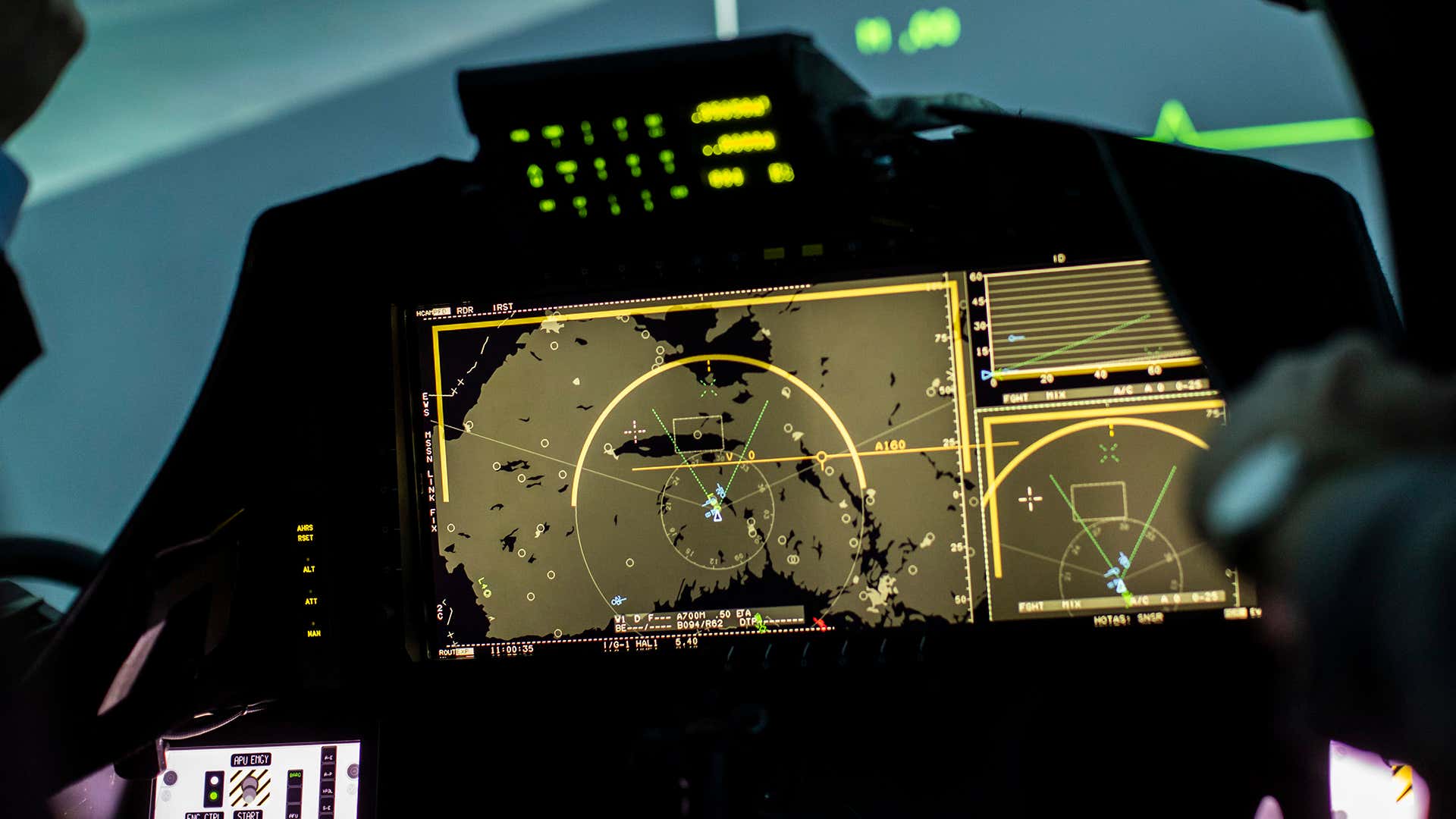
Also, look at the work they are doing with sensor fusion. Here is a later version of the radar display above, which is now a multi sensor display, and the HSD which fuses all inputs into a single tactical display.
This might be of an interest. 2 papers regarding the Gripen's Planned IRST.
This is the IR-OTIS but i guess the enhancements made on it in the paper goes into the Skyward-G.
This are some interesting part in the papers :
Comparison between measured range and modeling. This one seems for the "baseline" IR-Otis
The baseline IR-Otis appears to be compares very well with Russian NIIPP/NPK-SPP's OLS-35 and UOMZ's version of OLS-35. Although the OLS one doesnt mention target model.
There is however enhancements. Showed in this flight test results. Where against Viggen target it can be detected at 90 Km. Granted it's in supersonic but still.. impressive.
The note on enhancements. guess the enhanced IR-Otis or skyward G would be a killer on tail-chase. 114 km is basically can support long range shot, one only need to figure how to accurately measure range.
LINK 16 - a new dimension of secret data connection for Czech Gripen 12/1/2019Aleš Hottmar 1261 Views 21. zTL Čáslav , 211. tl , JAS-39 Gripen At the beginning of next year, the integration and flight tests of the MIDS-LVT terminals of the secret data link of the Alliance Protocol Link 16 on the Czech JAS-39 Gripen aircraft should finally begin. Link 16 is a standard protocol used by NATO countries to transmit tactical data information from ground guidance stations, AWACS early warning aircraft and between aircraft themselves. Now the machines of the tactical air force of the Air Force of the Czech Armed Forces will join this alliance standard.
Somewhat surprisingly, Sweden was the first country in the world to introduce systems for the transmission of tactical data information from ground command and guidance posts into real operational operations. The reason for their development and practical commissioning was the requirement for the ability to effectively manage the activities of the Swedish Air Force in the event of a major war. Surprisingly, a number of states did not recognize the benefits of the possibility of transmitting important tactical information using the so-called datalinka before, and some air forces do not have this necessary operational capability even today!
The Swedish Flygvapnet command was well aware that against the main potential enemy in the form of the Soviet Union, which was supposed to be able to use Swedish territory to achieve its other strategic goals in the event of war, its air force would not be able to operate from its permanent bases. using traditional command and control procedures, using, inter alia, an unsecured radio link, which is relatively easy to disrupt in the context of strong electronic warfare.
The FMR-10 transmitters of the STRIL 60 system were strategically located on the Swedish coast. (source: Swedish Armed Forces)
This led to the implementation of a strategic plan called Bas 60 (Flygbassystem 60), which included the construction of dozens of backup airports and designated road sections with parameters of 2000m x 12m throughout Sweden, on which in the event of war would quickly disperse before a possible attack Flygvapnet type fighters. Saab J-35 Draken or Saab J-32 Lansen and thanks to a nationwide distributed system of digital command and control commands called STRIL 60(Stridsledning och Luftbevakning 60) could continue to conduct effective combat operations. This data link system enabled the internal transfer of binary data from various STRIL 60 ground devices, as well as between the ground and the aircraft itself. All the calculations of control information for guiding the fighter aircraft to the target, which were provided by humans in the previously used STRIL 50 system, have now gradually taken over the computers, which has made it possible to speed up and make the whole process significantly faster.
The basis of the whole system were long-range radars PS-08 from the English brand DECCA Radar Limited, which were selected for STRIL 60 as surveillance and guidance radars. The PS-08 had a range of less than 500 km and for its time a good detection capability of targets flying at high altitude in the relevant air defense sector. The narrow beam angle (0.28 degrees) provided good accuracy in determining the position of the target. By the end of the 1950s, four stations with special nicknames in the form of male first names began to operate, and the first PS-08 "DICK" radar was installed at Vikbolandet in Östergötland. This was followed by "HARRY" at Södertälje's, "TOM" near Emmabod and finally "FRED" at Skåne. PS-08 worked with high output power and short pulses for good resolution of the target in the S band. The radar was gradually adjusted to better handle enemy interference,
In the electronic "memory" of the STRIL 60 system, all information from PS-08 radars was further processed for distribution to other users at the Luftförsvarscentral (LFC), who needed radar yield for their activities, for example to calculate optimal flight paths for different types of attacks and capture an enemy target. The data transferred in this form in the form of digital data commands or voice commands for J-35 Draken fighters was transmitted by the Stril system from FMR-10 transmitters from the German company Rhode & Schwarz, which operated in the VHF band in the frequency range 103-156 MHz and with a maximum output power of 10 kW, in peacetime reduced to 1 kW. A total of 41 stations were strategically installed on the Swedish coast, the transmitter antennas themselves were installed on a high mast and pointed obliquely upwards to cover the high altitude above the Baltic Sea. Command messages in voice form (for J-35A) or digital form (for J-35B / D / F) came via cable or radio connection, with the "wire" connection always being chosen in a combat situation for minimal risk of interference.
Draken - top secret !! The first generation of datalinka is coming PS-08 radar yield and STRIL 60 data transmission console operator (source: Swedish Armed Forces)
The STRIL 60 data connection in Draken was, in a way, an electronic miracle due to the time of its creation. It is worth noting that at the time when the Swedish Flygvapnet successfully put this device into service in the early sixties of the last century, the US Air Force began to experiment with similar systems.
The integration of the data connection to the Drakens was strictly secret, and the entire system of command information and commands was ingeniously hidden in a number of classic analog devices, so that a casual observer in the Draken cabin could not recognize anything at first glance. The data message from the FMR-10 transmitters was received by the Draken onboard radio. The J-35B / D machines were equipped with a pair of radios - Fr13 manufactured by AGA as the main radio and Fr 14 from Collins as a backup. Based on extensive testing, the Fr 14 radio became the main recipient of the data messaging function and the Fr 13 was used only for voice communication. In Draken, its rear antenna was usually used to receive control data, which had a large gain for signals coming from behind, which suppressed the expected radio electronic interference.
The Draken cabin was advanced for the time of introduction into service in the early 1960s. (source: Swedish Armed Forces)
The control data message from STRIL 60 contained an introductory specific code, which had to correspond to the individual code of a particular aircraft. If all was well, the message was distributed from the radio to the FD 10 / FD 11 control data converter, which converted the data to analog signals, which were displayed on flight indicators in the cockpit. For example, commands for the Draken pilot were presented in the upper window of the AHK (Avstånd Höjd Kommando) indicator, located to the right of the radar screen. The indicator had a rotating drum that displayed all 20 predefined STRIL commands, while the input signal determined which of them would be visible through a small observation hole. Each time the command was changed, a warning tone sounded in the pilot's headphones.
The AHK indicator thus provided tactical information to the pilot, which was displayed as words, and the altitude scale showed the actual altitude of the aircraft and the arrow the target altitude set by incoming messages plus the distance to the target. The FLI-25 gyrocompass, in turn, showed the direction to the target, the speedometer displayed the speed of the target, etc. The list of commands and other data literally led the pilot to the target, which was to attack without having to turn on his own radar or start communicating in any way on open frequencies.
Each STRIL data message contained 103 bits, of which 68 bits were direct flight information and the rest was set aside for technical information such as aircraft identity, etc. In electronic storage, incoming data messages from Air Defense Center exchanges were processed into a constant data flow. at 3000 bits per second. That means about 30 control data messages per second. In reality, this meant that if there were 30 fighters in the same area, each would receive an updated message per second.
The data message for J-35 Draken aircraft contained, in addition to the administrative part consisting of the so-called "Introductory Code" and "Address" (original identity of each aircraft), the following flight orders and data:
Phase of flight - contained two options, phase I for approach and phase II for ambush. The phase also served to scale the distance information. In phase II, at a distance below 40 km from the target, the distance resolution increased 10 times. The flight phase is transmitted with 2 data bits.
Target height - the height was sent in decimal format, which consisted of three decimal places with a resolution of 200 meters. The pitch was transmitted with 2 + 4 + 3 = 9 data bits. The specified maximum height for the J-35 Draken was limited to 20,000 meters, later for the JA-37 Viggen was increased to 30,000 meters.
Command - this function allowed the pilot to send one of 20 predefined text commands * with tactical content from the radar operator. These commands were transmitted with 5 data bits.
Target course - the course was sent binary coded with 9 data bits with a technical resolution of 0.703125 degrees.
Direction to the goal - was sent in the same way as in the case of the goal course.
Distance to destination - The distance was transmitted in binary coded 9 data bits. The resolution was 1 km at a distance of 40 km to 400 km. At a distance of less than 40 km during Phase II, the distances were transmitted with ten times higher resolution.
Changing the angle to the target- The rising or falling angle was transmitted using 6 data bits.
Height change to target - height change in meters was transmitted using 6 data bits.
Reserve - these were another 4 data bits that were not used in the messages
In the era of digital multifunction displays and powerful computers, it was a remarkable system that gave the Swedish Flygvapnet the ability to disperse to backup areas across the country and meet any air raid using ground-based radar stations, all without a single spoken word on open frequencies. The entire first generation datalinka system was implemented in 1963, first on the J-35B and J-35D Draken aircraft, and in 1965 it began to cooperate with the latest version of the J-35F Draken. The first generation of the data plant in Draken was, of course, chargeable to its time and allowed only one-way communication from the ground guidance station to the designated aircraft and vectoring to the starting position to attack only one primary air target.
The LFC (Luftförsvarscentral) had a total of 12 operator consoles in three cabins, with four operators in each. Each operator could handle four missions in one mission with one to four aircraft. In total, the operators in the LFC center could guide from their consoles 48 to 192 aircraft, which corresponded to 6 - 24 squadrons of Flygvapnet, so that a massive enemy attack by the Soviet Union could be prevented. Really respectable at the time. Note * - these were the following commands: FEL (error), HÖJDÄNDRING (height change), FLERA MÅL (multiple targets), JAKT (chase), REMSOR (?), NYTT MÅL (new target), OSÄKERT (unconfirmed), VARNING (warning), MÅLFART (?), MÅLKURS (destination course), O (zero), FRAM (?), TVÄRS (?), BAK (?), ÖKA (?), STIG (route), BRANT (?), KVARLIGG (?) And LANDA (ground).
Although Draken structurally dates back to the end of the 50s of the last century, its first versions already had on-board RL and a number of relatively sophisticated systems at the time. The picture shows the latest version of the J-35J Draken, which was modified in the number of 66 pieces of stored J-35F2 and all served in the years 1987-1998 at the F10 wing in Ängelholm. The "Johan" version was created due to delays in the supply of JA-37 fighters and the development of the new JAS-39, while it had the ability to capture low-flying targets such as Su-24 bombers, which began to come to the USSR Air Force and Naval Air Force. (photo: Aleš Hottmar)
The second generation of the datalink in Viggen - the possibilities are expanding
The introduction of the fighter version of the new JA-37 Viggen aircraft in the early 80's into the Flygvapnet armament moved the STRIL 60 system to a completely different level of capabilities. Viggen was the first aircraft in the history of aviation to use a modern on-board computer CK37 (Centralkalkylator 37) with integrated circuits as early as the early 1970s. This computer controlled, for example, on-board navigation, control of Radar PS-46 radar functions, displaying information about flight mode, orientation in space, engine control, fuel management, etc.
The original form of the dashboard of the fighter JA-37 Viggen, which was dominated by the EP-12 imaging system, which consisted of three indicators in the form of a transparent Sight Line Indicator SI (HUD), Target Indicator MI, which displayed all target data from the PS-46 radar and Tactical Indicator TI with a size of 5 x 4 “for the presentation of flight data, navigation and radar information plus a data link. (source: www.aef.se/ )
The fighter JA37 in its final serial version flew for the first time on November 4, 1977, and this version already had a more modern and powerful on-board computer CD107. The first series of Viggen fighters was delivered to a squadron of the F13 wing "Bråvalla" in Norrköping on June 25, 1980. Deliveries to the F13 were not completed until January 1982 due to delays due to engine problems. Another unit that acquired the Vigenny fighter was one of the squadrons of the F17 "Blekinge" wing in Ronneby, which received its first JA-37 in December 1981 and deliveries were completed in September 1982. In October 1982, deliveries to the third squadron of the F21 " Norrbottens' in Luleå, the last arriving in May 1983. Subsequently, the JA-37 was included in the armament of two squadrons of the F4 wing "Jämtlands" in Östersund in the period from August 1983 to April 1985.
In the mid-1990s, a major modernization of part of the Viggen fighters began, during which about 30 selected JA-37 machines from the F16 and F4 wings were upgraded to use new guided missiles and electronic warfare systems for deployment in international operations. The designation of such modernized Viggenes was changed to JA-37D. In addition to the upgraded cockpit, this version also received a new central computer CD-207. Otherwise, the original computer CD107 fighter versions of the JA-37, of course, cooperated with the STRIL 60 system. This meant that although he still received the same basic 103-bit message format as the J-35 Draken, he was able to work on the necessary calculations thanks to a more powerful computer and radar,
Display of information on a tactical indicator with CRT technology.
The cabin of the Viggen fighter was modernly equipped for its time and had both a Head-Up Display (HUD) and a pair of displays based on CRT technology. For example, the tactical display was already able to show the pilot much more data such as information about the attacked target, fuel and weapon status plus other information. The datalink itself enabled guidance to one main destination, or four backup destinations. Data messages were received via the FR-29 on-board radio, which converted the received analog information via digital transceiver into digital format, which was then transferred to the CD107 on-board computer on bus No. 3. The computer decrypted and analyzed received messages, error correction, importance assessment and was responsible for presenting this data on TI's tactical information display.
The development of the data line in Viggen, of course, continued, and in 1982 it already made it possible to connect two Viggen data to each other. Since 1984, even four machines, and in 1985 a two-way datalink was introduced. One aircraft could thus, among other things, automatically mediate the position of the target from its own radar, its own position of the aircraft and the state of armament for display on the tactical display (TI). This provided JA37 pilots with much greater situational awareness and enabled the use of a completely new air combat tactic. For example, it was possible to increase the distances between aircraft and cover a much larger tracking area, and at the same time it allowed to fly in a group in bad weather and at night much safer, and at the same time track the position of other machines in "combat". It was really a generational leap from the existing system, because for the first time, Viggen could share tactical data not only with each other, but also with ground systems, in real time. In 1995, the ability to transmit short text messages was launched.
In the mid-1990s, the JA-37D Viggen cockpit was modernized, replacing the original TI monochrome tactical indicator with a completely new 6 x 8 ”color TI 237 display, which was later used in the JAS-39C / D aircraft. The twenty-four-button MFD made it possible to display tactical data from the datalink much better. (source: www.aef.se/ )
Flygvapnet tested a new guidance tactic using a datalink, for example, against the US strategic reconnaissance aircraft SR-71 Blackbird. He flew through the edge of Swedish airspace about once a week, flying "Baltic Express" reconnaissance missions along the Soviet coast, and on his way back to his home base in Fairford, UK, he flew the narrow 3 km wide corridor of international airspace between the Swedish mainland and Gotland at 21,000m (70,000 ft) and Mach 3 speed.
As soon as the ground radar stations detected the incoming SR-71, the cash Viggen first reached an altitude of 8,000m (26,000 ft) and from Mach 1.35 the pilots swept to maximum speed and climbed at an angle of three to five degrees up to an altitude of 18,000m (60 000 ft), directly to the support course of the flying SR-71 and to the best shooting position for simulated firing of Skyflash missiles. During the raid, Viggen's pilots had a full tactical picture of the situation on their display, combining information from ground-based radars and their own radar to provide the precision needed to correctly capture the target at Mach 4-5.
The Swedish Air Force recorded over 50 successful interceptions of Blackbird, which were evaluated as those in which a simulated launch of Skyflash missiles would probably achieve a direct hit. It is difficult to imagine that Viggen pilots would have achieved the same success without the accuracy of guidance and data provided by the Stril 60 system. in the form of types MiG-23ML or Su-15TM, which in the 80s began to appear more and more often near Swedish airspace.
Viggen was the backbone of Flygvapnet throughout the 1980s and 1990s until the arrival of the Gripen. Again, a relatively underappreciated aircraft, with an effective weapon system, including medium-range missiles RB71 Skyflash and very decent flight characteristics and performance. The picture shows the AJS37 version, modified due to the delay of the entire JAS-39 Gripen program. Between 1992 and 1997, SAAB upgraded a total of 48 AJ37s, which acquired new avionics and a central computer, including 1553 data buses. This allowed the AJS37 version to use Gripen weapons, such as the AIM-120B AMRAAM or anti-ship RBs. -15F. (photo: Aleš Hottmar)
Very interesting two-seater version of the SK37E (Electronic), designed for REB lines and equipped with various jamming systems, which were controlled by the operator in the rear cabin. A total of 10 machines were converted to this version, serving in the years 1998 - 2002 at the wing of the F4 Jämtlands at the base of Frösön. The chosen camouflage coating was ideal for dispersion on the BAS 90 reserve areas in the summer months, and the ability to take off and land shortly was also phenomenal. (photo: Aleš Hottmar)
TIDLS - new capabilities of the third generation datalinka in the Gripen aircraft
The 4th generation JAS-39 Gripen machines have a completely new third generation CelsiusTech CDL39 (Communication and Datalink 39) with hardware from Rockwell Collins, better known as TIDLS (Tactical Information Data Link System), or "TAU-link “(Tactical Air Unit).
TIDLS is a high-speed two-way UHF datalink based on TDMA (Time Division Multiple Access) technology, which significantly expands the possibilities of data communication compared to the original system in Viggen. The Gripen system consists of two analogue Fr41 radios and a Rockwell Collins Fr90 digital radio, which operates in the 960-1215 MHz band and uses countermeasures based on frequency hopping and encryption. TIDLS was fully integrated into the new Swedish tactical radio system TARAS (Tactical Radio System), connected to the updated STRIL 90 systemand which provided radio networks for JAS-39 Gripen and JA-37D Viggen fighters, S100D Argus early warning aircraft, S102B Korpen machines designed for SIGINT and Stridslednings - StriC ground guidance centers. The Gripen concept already corresponded to the new BAS 90 system , which assumed the dispersion of groups of 4-6 aircraft on a large number of reserve areas and road sections with minimum dimensions of 800m x 9m.
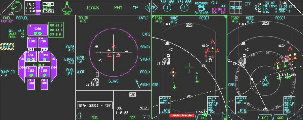
Display of information from TIDLS on the center display of the horizontal situation HSD (left) and the right multi-sensor display MSD. Green symbols indicate own forces, red enemy and yellow are unidentified targets. (source: Saab, https://saabgroup.com )
The Gripen datalink has two basic elements - air-to-ground and air-to-air connections with other aircraft. TIDLS can connect up to four aircraft in real time in both directions (some sources even state 8), the number of recipients of data information is not limited. The range is about 500 km and is highly resistant to interference, transmitted in short time intervals. Each of the four participants uses 25% of their transmission time. Data is transmitted via pre-programmed broadcast channels. The Swedish manufacturer claims that the only way to disrupt the data connection is to place an active jammer directly between the two communicating aircraft.
TIDLS basic modes include the ability to display the position, direction, altitude and speed of all four aircraft in formation, including basic information such as fuel status, weapons, countermeasures, and even the cursor position on the multifunction display to allow pilots to highlight important targets for other aircraft. TIDLS differs in part from a similar alliance system, the Link 16. It provides connections to fewer users over shorter distances, but connects them more closely together, exchanges much more data, and works in near real time. The Swedish datalink is updated every second compared to Link16, which is updated every twelve seconds. TIDLS allows up to four aircraft to be connected in both directions over a distance of 500 km and at the same time allows access to data from the SAAB 340 Erieye early warning aircraft,
Information from the TIDLS data plant, together with the output from the radar, the EWS39 electronic warfare system and a moving map, is displayed on the central HSD (Horizontal Situation Display) display, designed to visualize the tactical situation on the battlefield. Colored symbols distinguish between their own, enemy and unidentified targets and show who "targeted" whom. Similar data are displayed on the HUD viewfinder, where the symbolism again distinguishes between own, enemy and unidentified aircraft. If two pilots choose the same target, the system will show which of them is more effective to attack. The whole system is also optimized to prevent two Gripen from attacking the same aircraft, etc.
In combat beyond the visual reach of BVR, where information and situational awareness are the key to success, datalink provides an unrivaled advantage and a significant overview of the battlefield. It is no exaggeration to say that in a formation of four Gripen aircraft, each pilot immediately knows what the others see, do - and what they will do next. Each aircraft has access to the radar and sensory data of the others, allowing a small number of machines to defend a wide area. For example, in one Flygvapnet exercise, six JAS-39s were able to defend almost half of Sweden when three "pairs" of Gripen Combat Air Patrol missions were able to patrol the entire Swedish east coast, from the northern edge of the Baltic Sea island of Gotland to Ronneby Air Force Base. , and further to the southern tip of the country.
The STRIL 90 system also includes S100D Argus early warning aircraft, equipped with Erieye radar, which can use TIDLS to send their radar image data to long-range Gripen fighters. (photo: Aleš Hottmar)
Data can be exchanged with S100D "Argus" early warning aircraft (SAAB 340 AEW), and with the help of their Erieye radar, the Gripen formation can obtain a picture of the tactical situation at a much greater distance using a datalink, which significantly increases their combat range. Datalink TIDLS is also fully functional even when the aircraft is on the ground. The condition is, of course, all running systems and running APU (Auxiliari power Unit). This function is advantageous if the pilot is just getting ready to take off and has a perfect overview of the tactical situation in the air before takeoff.
Probably the biggest benefit of the TIDLS datalink is the ability to perform new covert air combat tactics out of sight of the target. Flygvapnet refers to them as "Samverkan", which could be loosely translated as "joint attack". One Gripen can provide radar data to other machines, allowing one fighter to track a target at a greater distance, while others in passive mode use this data for covert attack. Without an emitting radar, other Gripen aircraft are much less likely to be detected by enemy aircraft, giving them some surprise advantage.
An even more sophisticated tactic is to use the Gripen to upgrade the target for a medium-range AIM-120B AMRAAM missile. This tactic is used, for example, when one of the Gripen captures a target at a great distance, passes its data with TIDLS to another machine, which with the radar off can get much closer to the target and which fires an Amraam missile. It then makes a turn and escapes from the enemy's range, while the missile fired is updated with data from the first machine. This allows the activation of the missile guidance radar much later and thus shortens the reaction time for possible countermeasures of the target.
TIDLS also allows multiple fighters to determine the position of the target faster and more accurately using triangulation from several radars and RWR. The PS-05 / A radar of the Gripen aircraft itself can operate in passive mode as a sensitive receiver with high directional accuracy. Two PS-05 radars can exchange information over a data link and locate a target using triangulation. Datalink also helps to track the target more accurately. Typically, three "echoes" are required to capture and track a target in track while scan (TWS) mode. Datalink allows aircraft and their radars to share these echoes, so even if none of the aircraft in the formation have enough "echoes" to track the target, they can do so together.** or Thai Air Force.
Note ** - The South African datalink called Link-ZA is again a data connection based mainly on the TDMA method, which can operate on HF, VHF or UHF bands at speeds of up to 16,000 bits / s, with up to 16 platforms per network and at least three concurrent networks in operation. Through Link-ZA, the South African Air Force has adapted the Swedish TIDLS concept to share data on the radar situation between JAS-39 Gripen aircraft and Hawk Mk.120 subsonic machines, which do not have their own on-board radar.
The Thai Air Force uses its national Link-T data link system, which is based on the Swedish TIDLS. Thai Gripen can thus obtain data information not only from ground stations, but also from the Thai mini-AWACS Saab 340 with Erieye radar. Link-T is also installed on Thai Northrop F-5E aircraft. (photo: Peter Liander, SAAB, https://saabgroup.com)
Alliance standard Link 16 on the Swedish Gripen and in Operation Karakal
The Swedish datalink TIDLS is undoubtedly a top system, but it has one significant flaw in its beauty. It is incompatible with a similar Link 16 device, standardly used in NATO. Of course, the Swedish side was fully aware of this problem and, due to the planned involvement of the Swedish Air Force in a number of international exercises and alliance operations, planned the implementation and full certification of Link 16 in Flygvapnet in 2008. Swedish Flygvapnet was made possible by upgrading their operating software MS19, which was announced in 2006.
The Swedish FMV (Försvarets materielverk) subsequently concluded a contract for the purchase of MIDS-LVT terminals worth USD 29.6 million, which was acquired by Data Link Solutions (DLS). Deliveries took place in 2011-2012 and the terminals were installed on JAS-39C / D Gripen fighters, S100D “Argus” early warning aircraft (SAAB 340 AEW) and various land and sea platforms. MIDS-LVT terminal for distributed sharing of encrypted digital location information using the Link 16 alliance protocol (photo: www.viasat.com )
MIDS-LVT is a compact terminal for distributed sharing of encrypted digital position information, which works on the principle of time division multiplexing. It provides data links to air, land and naval platforms, enabling simultaneous coordination of forces and situational awareness in battlefield operations. Individual users involved in the Link 16 alliance information network thus share very similar information as in the case of the Swedish datalink TIDLS, such as the flight parameters of each specific aircraft, including the rest of the fuel or the current amount of ammunition carried and the like.
The pilot of an aircraft equipped with a MIDS-LVT terminal again sees on his MFD display all air targets in his vicinity, including their identification and description, without using his own radar or other sensors. Link 16 also enables direct control of network subscribers, or mutual communication by means of short text messages. If necessary, it can also be used to transmit smaller amounts of image data and voice communication.
The Link 16 protocol itself uses the UHF frequency band for its operation, in the range of 969 to 1,206 MHz, and the connection can be implemented up to a distance of around 900 km. To enable simultaneous access of a large number of subscribers to the network, a method called TDMA (Time Division Multiple Access) is used, in which the transmission is divided into short time slots, which are allocated to individual terminals. In the case of the Link 16 system, the length of one time slot is 7.8125 ms, with the basic unit used in network planning being a 12-second cycle containing a total of 1,536 slots.
The specialist of the Swedish contingent FL01 uploads a cryptographic key to the MIDS-LVT terminal of the JAS-39C Gripen aircraft via a data cable. (photo: Försvarsmakten)
This is probably the biggest difference from the Swedish TIDLS system, which does not allow the connection of such a large number of participants to the network, on the other hand, it paints a picture of the situation in almost real time under 1 sec. The transmitted information is of course encrypted and the transmission is also highly resistant to interference, thanks to the technology of so-called frequency hopping, where individual terminals "retune" frequencies when transmitting according to a preset and coordinated scheme at a dizzying rate of 77,000 changes per second. MIDS-LVT terminals have their own antenna and are themselves capable of transmitting with a power of 200 or 25 W (depending on the mode). When transmitting image data, the data throughput is 26.8 to 1102 kbps, while the throughput of voice communication is 2.4 kbps (LPC-10 codec) and 16 kbps (CVSD codec).
A major challenge for the Swedish Flygvapnet was the integration of the Link 16 system on the JAS-39 Gripen aircraft before deployment in the Libyan operation Karakal. The technical side of the case and the installation of "hardware" in the form of MIDS-LVT terminals in the Gripen was practically problem-free and the first testing took place during a joint exercise with the Norwegian and Finnish air forces in northern Sweden in March 2011. to access the Link 16 secret network during Operation Unified Protector, as Sweden, as a non-member country of the Alliance, of course did not have access to the secret network at the start of the operation. The licensing process itself was very difficult and was not resolved until Operation Unified Protector.
Implementation of Link 16 in the Czech Republic and its integration into Czech Gripen
As in Sweden, the officials in the Czech Republic were clearly aware that the introduction of a distributed data link of the Alliance Protocol Link 16 in the Czech Army is an absolutely necessary necessity in the future. After all, Čáslav fighters with Gripen aircraft in recent years have already significantly reduced the absence of the Link16 system to a number of large alliance exercises, during which they could not receive an image of the air situation from the ground control station GCI (Ground Control Intercept) or AWACS aircraft via datalink, which was of course relatively large handicap.
The implementation of MIDS LVT (4) (Multifunctional Information Distribution System - Low Volume Terminal) ground terminals was first started, with the 261st control and awareness centers in Stará Boleslav being acquired by the first two terminals in 2010, but they were not put into trial operation until Subsequently, they were integrated into the computer system CSI (CRC System Interface), whose monitors can display all data obtained through the Link 16 network. Airmen in the rugged Old Brno CRC can share data with, for example, AWACS aircraft or other machines connected to the relevant networks. This network was created jointly for AWACS aircraft and air force machines of Germany, the Netherlands and Belgium. Subsequently, the Czech Republic was also allowed to enter it.
TIDLS enabled Czech pilots to develop a tactic of greater pair spacing during BVR fights, which they then successfully used in a number of alliance exercises, where they were able to surprise and defeat even more powerful opponents by loading a picture of the tactical situation via datalink. (source: Stejsy, www.armyweb.cz )
The whole implementation of distributed data systems such as Link 16 is, of course, a long-distance run, which requires a number of very professional trainings to understand the whole issue. For example, from 5 to 9 August 2019, the Link16 Joint Interoperability Course took place at the University of Defense in Brno, which brought together mainly ACR Air Force staff supplemented by specialists from other parts of the ACR, preparing the implementation of the Link 16 communication environment in the Czech Republic.
The course is part of a comprehensive training provided through the Joint Interoperability Division, deployed in Fortt Bragg, USA, which aims at an internationally recognized Joint Interface Control Officer (JICO) qualification in an alliance environment. In the ACR conditions, the National Group of Data Line Management and Control, integrated into the structure of the 261st Control and Reporting Center (CRC), is entrusted with the planning, management, evaluation and monitoring of Link16, ie selected functional responsibilities of JICO.
With its content, the course provides basic theoretical education in the field of Link16 technology, ie a basic amount of knowledge necessary to understand the functionality of this tactical data link and its use not only in Alliance operations. This level is generally intended for operational and technical personnel. Higher follow-up courses are then intended for staff who ensure the planning and management of multiline operations. Follow-up courses use simulation technologies and in the final phase of comprehensive training, students participate directly in alliance operations in the form of exercises using a variety of tactical data lines. Each subsequent phase of this training is determined by extensive practical operational experience with the planning and management of tactical data lines,
The MS20 software also brought the so-called Digital CAS, ie the possibility of exchanging data with ground FACs.
A separate chapter is the introduction of the Alliance data link format Link 16 directly on leased Czech aircraft JAS-39C / D Gripen, which were ready for its integration during the modernization in Sweden in 2016-18 and the subsequent transition to the latest version of operating software MS20 in spring 2018. The contract itself for the purchase of 15 pcs of MIDS-LVT (Multifunctional Information Distribution System) on-board terminals from the American manufacturer Viasat Inc. in the estimated value of CZK 150 million without VAT, the army signed in August 2017, stating that their integration and installation would be carried out by its own forces. Purchased MIDS terminals will probably be in the LVT (4) version, ie without the TACAN system. A total of 14 pieces will be integrated directly into the aircraft, one will serve as a backup. MIDS terminals were acquired and introduced into the ACR as their own property.
The contract also includes the initial setup of integrated logistical support for the operation of the system, including training in 2019-2020. The logistical support of the system includes the supply of diagnostic equipment, special tools and consumables for use. As this is a special covert technology, it had to be procured exclusively under the Foreign Military Sales (FMS) regime under a contract concluded directly with the United States Government. The actual delivery and installation of MIDS on-board terminals in the JAS-39 aircraft and subsequent flight tests after installation should take place around the beginning of 2020. into alliance operations. text author: Aleš Hottmar , czechairforce.com
The author will be very grateful for any additions or clarifications to the information contained in the text and at the same time apologizes for any errors, caused mainly by translations of Swedish materials.
The Swedish third-generation datalink TIDLS was launched on Czech Gripen in 2006 during the transition to the new version of the operating software MS18.7. However, the Czech Republic did not purchase a ground terminal for it, so the Gripen could only communicate with each other. Over the next few years, TIDLS was further upgraded with MS19 and MS20 operating software updates. Now the Czech Gripen will finally get the opportunity to join the Link 16 alliance network and, thanks to ground terminals, they will also be able to receive an image of the tactical situation from the ground CRC. (photo: Aleš Hottmar)
Here the link to the original article in Czech (Google did the translation for the text above, there's the occasional problem but everything essential is correct):
The author did a very good job of describing the history and the key features. His open sources are listed at the bottom (but he also has profound link knowledge IMO).
He had some problems to describe the meaning of some of the Swedish short form commands of the STRIL 60 GCI data link to the J35 D, E, F Draken aircraft. Here filled in/corrected:
Note * - these were the following commands: FEL (Error), HÖJDÄNDRING (Altitude change), FLERA MÅL (Multiple targets), JAKT (Fighters), REMSOR (Chaff), NYTT MÅL (New target), OSÄKERT (Unconfirmed), VARNING (Warning), MÅLFART (Target speed), MÅLKURS (Target course), O (Zero), FRAM (Collision course), TVÄRS (Abeam), BAK (Rear) (these last three describe the type of intercept), ÖKA (Speed up), STIG (Climb), BRANT (Steep turn), KVARLIGG (Stay) and LANDA (RTB).
The article outlines the key difference between a C3 data link like MIDS over LINK16 and TIDLS or the Swedish Fighter link.
From the article: "The Swedish datalink is updated every second compared to Link16, which is updated every twelve seconds ". This is also why the TIDLS has only four active members (and unlimited listener members). The link information is real-time, meaning it can be used for cooperative targeting/tactics/EW/Communication.
A MIDS link is tactical and enhances SA (Situational Awareness) but it can't be used for sensor sharing/targeting as target updates can take 12s. Also, communication in text or digital voice is not real-time. A "BREAK!, BREAK!" from the wingman might come when the missile has hit. A Fighter link serves such purposes.
In essence, a modern fighter shall have two links: A MIDS type link for C3/SA/GCI, then a real-time link for the Tactical unit for cooperative SA/Targeting/Tactics/EW/Com. A Gripen has both (Swedish GCI/MIDS, then TIDLS) whereas an F22 has the latter but not the former (as Link16 is Pseudorandom spread spectrum and frequency hopping but not Stealth. It serves as a beacon to the aircraft for any transmission if you have a sophisticated receiver).
Note * - these were the following commands: FEL (error), HÖJDÄNDRING (height change), FLERA MÅL (multiple targets), JAKT (chase), REMSOR (strips/chaff), NYTT MÅL (new target), OSÄKERT (unconfirmed), VARNING (warning), MÅLFART (target speed), MÅLKURS (target course), O (zero), FRAM (front), TVÄRS (across), BAK (behind), ÖKA (increase), STIG (ascend), BRANT (steep), KVARLIGG (remain) And LANDA (land).
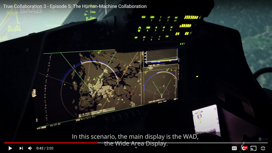
The display functions including MFDs and WAD are well described in an excellent "The Drive" article by Jamie Hunter from last week (best one about the Gripen E so far), worth a read:
Sweden's Bigger Badder Gripen Fighter Packs A Lot Of Punch In An Incredibly Efficient Package
Advanced cockpit and sensor fusion
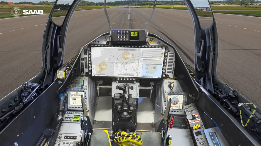
Monitoring all of these advanced systems, the pilot sits in front of a completely new cockpit layout. After much deliberation, the Swedish Air Force decided to follow Brazil and opt for a single Wide Area Display (WAD) in the Gripen E. This is an evolution over the three large displays in the Gripen C/D cockpit. “The WAD adds huge possibilities for the pilot regarding situational awareness and the ability to act on this,” says Nordlander.
Saab has spent a tremendous amount of time fuzing the Gripen E’s range of sensors and presenting swathes of data to the pilot in an uncomplicated and intuitive manner. “We have chosen to have a map across the entire area of the display, and have your position shown wherever you want it to be, but to start with it is centered. The modern battlefield is geographically huge and the pilot needs situational awareness over a vast area. So on the map, we have overlaid mission routes, other platform detail, and all relevant objects in the air and on the ground.”
JAMIE HUNTER
A Gripen E pilot wearing the Targo II helmet and manipulating the Wide Area Display.
“The WAD has touchscreen functionality, and the pilot can create regions of different sizes and various information. Sensor views can be overlaid and can vary in size and zoom. In the Gripen C, we found that pilots change map scaling a lot because you may have detailed interest in one area, simultaneously with the need to monitor a zoomed out larger area — in Gripen E we increase the SA with the possibility to overlay one or several maps of selected areas and zoom level.”
“Our testing has found that the possibilities with the WAD presentation are almost too flexible, so we are recommending default setups that mean the pilot actually decides and pre-selects these in the mission support system [MSS] on the ground, then they can swap between them during the flight. You can create a table in the MSS then fast access in the aircraft as to how you want WAD to look. Then you can deviate from those main set-ups if required.” Nordlander says the Gripen E test team is carefully proceeding with how it introduces the new display. “There are touch functions that may or may not be used by the pilot, and there will be times they want to use HOTAS [Hand-On Throttle And Stick], push a button, or turn a knob. We would never accept functionality only via touch.”
Saab has chosen the Targo II Helmet Mounted Display (HMD) for the Gripen E. Unlike the F-35, for example, the cockpit blends the HMD and WAD with a Head-Up Display (HUD). “We prefer the redundancy of a large HUD and an HMD. We had a lot of discussions, but we weren’t ready to go with a non-HUD layout [as in the F-35]. Also, sometimes pilots may want to fly the jet without having to wear the HMD, so we offer choice.”
JAMIE HUNTER
A Gripen E test pilot wearing the Targo II Helmet Mounted Display.
“We have a lot of experience that has evolved through the years when it comes to Human Machine Interface [HMI]. In the Gripen, this is designed to select and filter critical items for the pilot. For example, we don’t show engine RPM [Revolutions Per Minute], we don’t show which tanks the fuel is in unless required. If the system is working perfectly well, it won't tell the pilot anything. We have automated a lot of the functionality in the system. This is a huge step forward in performance and how we use the system.”
“The pilot is able to select the level of automation they want, based on the scenario. In Gripen C we have already gone with this principle. So a pilot can select to use systems manually, semi-automatic, or totally automatic. It means the pilot can decide that they want to monitor and manage everything, select to approve or reject suggestions from the system, or do what is best according to the system. This information is presented via symbols on displays, by sounds, or by speech messages, depending on the mode. Essentially, we are trying to make it as easy as possible for the pilot to make critical tactical decisions.”
Saab explains that it sees Human-Machine Collaboration as the next step in ensuring that the platform and pilot work together, further enhancing the possibilities of sensor fusion, adaptability to missions, and even learning. “When it comes to sensor fusion, this is all about maintaining the absolute maximum situational awareness. You can have the greatest kinetic performance in the world, but without situational awareness, you’re a sitting duck. In Gripen E we talk about transparent fusion. I need to know what sensors/platforms are providing which data and what the quality of that data is, to be able to make the best possible decision! It is also crucial to know what the opponent knows about me, in the decision making.”
SAAB
The Gripen E Wide Area Display being evaluated in a simulator.
“We also have a fusion between platforms. In Sweden, we started flying with a fighter-to-fighter data link at the beginning of the 1980s in the Viggen. The idea came from being outnumbered by an opponent, so we created it as a force multiplier in order to share information — to see what your wingman sees. This created a tactical behavior and a lot of experience which has helped us to create a system that is able to cope with a far more complex tactical situation.”
“We also use onboard simulation/calculation from the mission data to provide the pilot with suggestions for the best course of action. Depending on the opponent, it can tell the pilot when the other aircraft may have a launch opportunity on them, and things like if they crank left now, for example, what would happen. It’s extremely enhancing as an operational feature. So a pilot doesn’t just look at the displays and work out for themselves if they are in danger, or not, the aircraft can actually inform and suggest actions to the pilot, kind of like a what-if, all the time.”
JAMIE HUNTER
A Gripen E during testing in Sweden.
When it comes to training, the Gripen also includes embedded synthetic training scenarios. So a single ship can go out and fight a simulated bandit in a Beyond Visual Range (BVR) air-to-air fight, for example. “We don’t need to have all of those entities airborne,” Nordlander explains. “Because most modern air forces don’t have an unlimited number of airframes, we need to be able to create complex large formation situations, without necessarily having all those assets in the air. It’s all part of the embedded synthetic training in the Gripen E, so we can mix live and synthetic.”
“We don't only have air targets, we can also include simulated Ground-Based Air Defense [GBAD] systems and ground targets, and all of this can be pre-programmed in the MSS. So a squadron can fly a single or two-ship mission, and have that formation countered by GBADS, simultaneously with a synthetic BVR scenario. So, if you can only go out and fly a single ship, you’re not limited to just flying loops all day!”
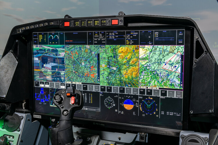
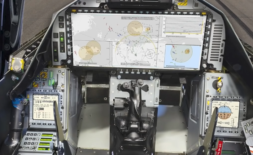
Here the latest cockpit display with the series production WAD and MFD configurations. The light grey displays are in day mode with very light colors to avoid problems with eye light accommodation going from outside to inside view, the WAD in night mode with darker colors is to the right and above. Observe the absence of a lot of cluttering info like you can see in the proposed Typhoon WAD and the F-35 WAD to the right (and other US WADs like F-15 and F-18). At right a closeup of the WAD and MFDs in day mode. Note the throttle handle which has the Gripen unique top of the handle movable (join 2/3 down) to acts as a large throw joystick to move the cursor over all three displays for point and click selections. Your throttle movement is still there as it's a trivial translation movement done with your palm bottom moving the last 1/3 of the throttle. The throttle joy is the preferred selection mode by Gripen drivers. The throttle has a TDC as well for fine alignments if needed for target acquisition work. In addition, there are dynamic edge buttons and touchscreen functionality for the WAD. You use what suits the situation best. The F-35 touchscreen-only mode was recently criticized by an F-35 driver in a Hush-kit article.
In the day view the 39-E is heading east direction Baltic sea from the SAAB site in Linköping (light grey land, dark grey sea), in the night view he's over south Stockholm heading south. The highlighted part of the landmasses on the night WAD is IMO ground map radar returns superimposed on the synthetic map picture. ESM, Radar, IRST, GCI, and fighter link data are superimposed on the map. The ESM and IRST tracks are derived from in-group triangulation as these are angle only sensors. The triangulation plus a lot of other info goes through the real-time fighter link. All is fused with the transparent fuse philosophy described above. The concepts follow the Gripen "Don't need, Don't see" HMI philosophy praised by all its pilots.
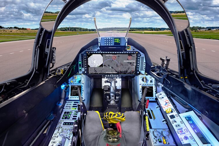
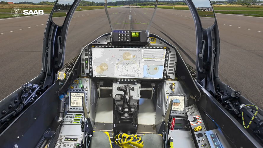
Here are pictures of the Gripen E pre-series (first) and series (second) cockpits with changes.
Some comments:
- The consistent use of software-controlled multi-LED buttons with 8 characters is clear to see for different panels.
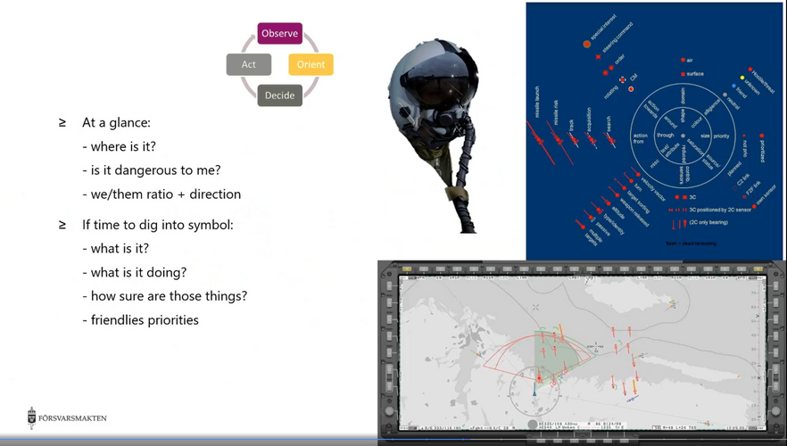
- It seems the WAD colors have settled on shades of grey, a light palette for day-light (first picture), and dark for the night (second picture). The light grey palette for day use is consistent with light colors for the complete cockpit to minimize eye light accommodation between outside and inside. The final selection of shades of gray for maps (greens, browns were tested) is probably to make tactical overlays stand out more clearly. The Gripen E tactical symbology was presented in a Swedish presentation (third picture). The objective is; you get the situation at the first glance, then you can drill for more info if you have time.
Differences between preseries to series:
- The LED buttons left of the WAD are cleaned up to one row, possibly for quick selection of WAD setups readied on the preflight MMS, Mission Support Station (the ones to the further left are for the FBW modes, to the right of the WAD is the warnings panel).
- The Targo HMD optical alignment unit for the hybrid optical/inertial tracker is placed on the left windscreen rail (the circular device with optical windows).
- A mount for the Targo HMD night vision goggles is on the right rail of the cockpit.
- There is a new parameter setting unit below the Radio panel on the left. It has adaptable LED buttons displaying the sensor commands and parameters you like to have there, like: PWR, RSET TRCK, ACM... You regulate parameters with the rotating knobs (awkward to do with HOTAS/Panel commands).
- The division of data between WAD and the two MFDs is clear to see. Tactical data on the WAD and secondary data (Fuel, Weapons, Links, CMDS status, backup ADI..) on the MFDs. Follows the Gripen HMI principle "Don't need, Don't see" for the primary displays (HUD, WAD), loved by fighter pilots who's flown it. Your SA is instantaneous, you don't have to sift through gobs of info to take in what's going on. Your brain cycles in a fight are too limited for to use them for sifting through stuff you don't need right there and then.
- The right mission cassette insert is now in a box with a lid. Could hold other stuff it seems like gloves etc.
Overall, the Gripen HMI has consistently been rated as the best in the industry, it has raised the bar again it seems..
Observe the absence of a lot of cluttering info like you can see in the proposed Typhoon WAD and the F-35 WAD to the right (and other US WADs like F-15 and F-18).
That description isn't really fitting since you don't know in which display mode the Eurofighter and F-35 are showing. One of the biggest advantage of a LAD over traditional MFDs is its configurability in fact. There are other pictures of F-35 for example with different LAD information, showing less "cluttering" or whatever you are trying to imply. Also there were countless reports from both the military and the media regarding how F-35's information fusion and HMI is best of its class, basically unparalleled by any 4.5th gen fighter. Arguing otherwise would be ill-advised.
I suspect claims to have the best display should be taken lightly, F35 included. So the Swedes may have the best, but there again….Just because many have flown the F35 and are impressed doesn’t mean it’s the best! The Swedes have a small market penetration so few will have seen their display or operated it…..also the history of the swedish datalink projects is considerable, having been up and running before Link 16 was even proposed, and this means they have had the longest time to understand and apply what they know to produce an expert system. Don’t be taken in by the claims of the great USA, who will always tell you they have the best, when it’s apparent that that cannot always be true! What they are really good at is selling.
That Vixen 500.. if it does contain 500 TRM's the center coloumns contains about 336 while rest of the coloumns at the edge of the antenna contains about 164.
But well i could be wrong. Counting just the columns tho (24) and assumes half wavelength spacings give width of the antenna to be 36 cm. One could assume pencil beamwidth generation, therefore same 36 cm could be the height of the antenna. The module counts turned to be 450 TRM's. That assumes 10 GHz as center frequency. If the radar operates in higher frequency say 11 GHz as center frequency It can have 549 TRM's assuming 100% "fill" efficiency for the antenna. The operating frequency bandwidth can be expected to be about 5.4% the same as the beamwidth of the antenna.
The range doesnt look bad at all and to be expected within the fighter radar of its size.
The PS-05/A radar comprises six Line-Replaceable Units (LRUs):
Antenna Unit: lightweight 600 mm diameter low sidelobe monopulse planar array, with guard channel antenna, IFF dipoles and digital servo control, weighing 25 kg
Power Amplifier Unit and Transmitter Auxiliary Unit: 1kW average power, flexible waveform, liquid cooled, TWT
system. These two LRUs weigh 73 kg altogether
High-Frequency Unit: multiple channel receiver, monopulse design, pulse-to-pulse frequency-agile, microwave integrated circuit
design, internally software controlled, 32 kg in weight
Signal and Data Processor: Ericcson D-80 processor, employing ASIC technology, hardware optimised for programming in Pascal, weighing 23 kg
Some of these information only applies to the first batch of the Gripen.
Here's an excerpt from JED article written by Michal Fiszer, uploaded to key pub by Sign, shamelessly cited by me :
Batch 1 Gripens also received the Rockwell Collins (San Juan, CA) (then Kaiser Electronics) head-up display (HUD) and the Ericsson Microwave (Gothenburg, Sweden) PS-05/A radar. The radar was equipped with a parabolic monopulse antenna developed from the UK's Blue Vixen radar employed by the Sea Harrier FRS.2. The antenna was developed by BAE Systems (then GEC Marconi). Initially, the radar had a range of about 100 km, more or less equal to the Russian MiG-29, the Gripen's potential opponent. However, the larger MiG-29 has a higher radar cross-section than the Gripen, which enables the latter to detect its adversary earlier and gain tactical advantage. The PS-05/A radar on the Batch 1 aircraft used the Ericsson D-80 processor, enabling it to track up to six airborne targets simultaneously and engage up to four of them with the use of AIM-120B AMRAAM missiles. Batch 1 aircraft avionics were integrated with two mission computers, SC-1 and the SMU, and three Mil-Std 1553B data buses.
The next 76 single-seat aircraft were built to the Gripen A Batch 2 standard. They were much improved and represented the first fully operational standard. The avionics system received a single (but more capable) Ericsson mission computer. The radar received a new EP-80E processor, increasing the number of targets that could be tracked simultaneously to 10. Now the radar could perform long-range search; track while scan (TWS); multiple priority target tracking; short-range, wide-angle search and track (combat-maneuver mode); single-target track; and raid assessment. In the air-to-ground mode, the radar could perform long-range search; land and naval priority target track; ground mapping; and surface ranging (for the gun and unguided rockets).
But above all, the Batch 3 is to receive a new Ericsson PS-05/A Mk3 radar, which has just been developed. The radar has a new D-96A high-speed processor with greatly increased computing power. This has enabled some new modes to be incorporated, as well as the ability to track in excess of 20 targets simultaneously (the precise number is classified). The radar range reaches 130-160 km, depending on various factors. In air-to-air search mode, a pilot can select among three patterns of search: 2x120º, 2x60º, or 4x30º. The search rate is 60 degrees per second. An improved radar transmitter and receiver provide good frequency agility and allow variable waveforms: low, medium, and high pulse-repetition frequency (LPRF, MPRF, and HPRF, respectively). The latter mode is used for long-range velocity search (VS) with no ranging, while the MPRF is used for track while scan (TWS).
Though there's one thing puzzling for me, and that is an information disclosed in a paper published in EURAD in early 2000s by an Ericsson engineer. In that paper, it is mentioned that :
[...] a programmable Singal and data processor was developed, that is now in use in the first two batches of the Gripen aircraft.
At the time the 3rd batch of aircraft was ordered, the time was ripe to transfer the signal processing algorithms into a more general COTS family of processors. Contact was taken with different companies, and Mercury Computer Systems was chosen for the signal processing hardware and development system. Data processing is based on the Ericsson Modular Airhome ComputerSystem. MACS uses COTS CPUs as design elements and is also used for the Mission system and the Display system.The newly developed Signal-and Data Processor (SDP) is now delivered together with upgraded Radar Software to the new production aircraft.
So firstly, I'm not sure if the EP-80E was in use for PS-05/A at all. Secondly, I'm not sure if D-96A is a "COTS processor" this Ericsson paper is mentioning. From other sources I found, it is mentioned that not only the computer system but the processor in the Mercury signal processing computer was also developed by Mercury. Anyways, I've had a hard time finding information concerning this particular processor. Mercury Computer Systems by the way is a Massachusets company, so it's another major foreign input for the Gripen avionics.
Anyways, this version of PS-05/A with COTS processors is called the PS-05/A mk.3 JURA (JAS Upgraded Radar)
Ericsson/SAAB's airborne AESA development could be traced back to 1996. They've started a programme called "Not Only Radar" or NORA in short. The programme comprised of 3 stages, NORA I to III, and was ultimately aimed at developing AESA MFR for future use in Gripen upgrade/future variants.
NORA I was a study programme that was meant to be the first stepping stone towards a more complex AESA MFR system. As a result of NORA I, a small X-band subaperture on a breadboard structure that consisted of 108 active TR elements was developed. The subaperture was surrounded by a ring of passive radiators. Each TR unit consisted of two TR functions and radiation elements coupled into a single unit. Radiating element was a dual polarized dielectric loaded on a circular waveguide.
AESA and TRM structure were as follows :
As you can see, TRM was a hybrid of MMIC t/x and HMIC r/x section. t/x MMIC was of HBT architecture and has demonstrated output power of over 5W with PAE exceeding 40%. r/x HMIC was a hybrid structure of GaAs HBT coupled with PHEMT and Si diode switches (I wonder if Ericsson engineers considered HBT-HEMT integrated MMIC instead of HMIC, but since the paper mentions small dimensions and low cost, I think the problem was the maturity of hybrid integrated MMIC at the time). Receiver HMIC demonstrated a noise figure lower than 2.5 dB, gain exceeding 30dB and TOI exceeding 35dBm.
Since lab conditions were assumed, feeding network was very much simplified. However for cooling structure requirements, a full scale system of around 2000 elements were assumed and implemented in miniature scale.
The X-band subarray developed and demonstrated was the technological basis of Swedish antenna front-end system that was considered as a candidate for NORA III demonstrator.
NORA I was followed by a more ambitious prototype radar development programme, called the NORA II and III. In this phase of the programme, Ericsson aimed to develop a full-scale, complete AESA radar. NORA II was a definition phase of this complete radar, whereas NORA III was a prototype construction, test and evaluation phase.
Overall, there were several study areas/capabilities in the NORA programme, but the following were among the most important :
Multi-function concept
Signal processing modernisation
Compact receiver design
TRM design for X-band
SAR/GMTI demonstration
AESA subsystem definition
AESA radar demonstration
The programme was called "Not Only Radar" since the goal was to demonstrate different RF functions, mainly :
Active beamforming and steering capability for wideband, wide angle, multi-beam radiation. Also important was signal and data processing capabilities, that are able to process all the data obtained by the AESA.
RF interference (Jamming)
Broadband communications
Simultaneous SAR mapping and air target tracking operations through true TDM
so it was basically a modern AESA MFR development programme.
Although, as noted above, several X-band TRM designs were studied, different solutions for antenna sub-system acquisition was studied. Some of them were internal Swedish options, though others were European and US alternatives. The choice was made by a steering committee consisting of Ericsson, SAAB, FMV, etc. The three most important criterias in choosing antenna sub-system acquisition strategy were :
Common interests with the partner
Cost and risk reduction
Time
In the end, Raytheon (then Hughes, now RTX) was chosen as a programme partner. To partner with Raytheon, the most important prerequisite was to get license agreement in place. The programme goal was identified to be demonstration, test and evaluation, not the acquisition of antenna technologies, so this was straight forward. Antenna sub-systems were packaged in a black-box, and the agreement outlined that the antenna sub-system was to be returned to Raytheon after a finite period, once the demonstration programme was over. There were in total 7 Design Reviews, which were followed by a flight test programme. The flight test was conducted on a modified JA 37 Viggen aircraft (from summer of 2005), as well as mounted on rear ramp of Flygvapnet C-130 (between 2006 and 2007). The latter was especially important since a conatinerized monitoring and recording equipment was housed in a 20ft container and was loaded into the aircraft for test data gathering. These data were then evaluated on ground.
I unfortunately was not able to find definitive test results. Also, some sources mention that the US government rectricted the export of NORA III based radar with similar design, featuring US technologies (antenna system). This is opposed to the advisory opinion concerning exportability of the radar system that Ericsson commissioned, which was positively answered by the US (I'm not sure though, if such advisory opinion was requested to Raytheon or the US govt.). Though if true, it would be able to explain why Sweden opted for European AESA radars for the Gripen NG.
Technologies developed and demonstrated through NORA programme are implemented on current PS-05/A mk.4 GRETA and future mk.5 AESA radars. I guess that the main hurdle for SAAB was to develop their own atenna subsystem. Original schedule outlined by SAAB during mid-late 2000s was that a PS-05/A based AESA radar would be ready for deployment by 2012. This of course was not the case. Also, during the 2000s, NORA was often mistaken as the nickname given to the mk.5 radar but as you could see, NORA program proceeded mk.4 and mk.5 variants.
While NORA II and III was proceeding Ericsson/SAAB was also undertaking another AESA programme called the GENA (Generic AESA Demonstrator) which was later followed by a joint Italo-Swedish programme called M-AESA with Selex and Elettronica. I will post some more details later.
D80 computers were used on the prototypes and the first few production Gripens but the D80E computers replaced it on 39108 (7th production single seater I think).
The D96 / MACS are the same thing, built with 266MHZ PowerPC 740 COTS processors and aimed at being 10 times faster than the D80E.
D80 computers were used on the prototypes and the first few production Gripens but the D80E computers replaced it on 39108 (7th production single seater I think).
The D96 / MACS are the same thing, built with 266MHZ PowerPC 740 COTS processors and aimed at being 10 times faster than the D80E.
Thanks for the clarification. So I was citing wrong information afterall. Also, I guess the way they've used the word "processor"s in the sources I've cited are similar to how "processor" is used in ICP. So more a computer system, rather than a processor in more common sense.
I'd like to ask one question though, and that's if this "EP-80E" and D-80E are the same computers. Are you aware of EP-80E, or this another error in the JED article?
PS-05/A multimode multimission radar for the JAS 39 Gripen
Type
Airborne multimode radar.
Description
Ericsson Microwave Systems AB produces the multimode, multimission, |-band (9 to 10 GHz), pulse Doppler radar for the JAS 39 Gripen.
Ericsson collaborated with GEC-Marconi for the development of the PS-05/A [actually, Ferranti who were bought by GEC - Admin], which, in original configuration, shared some elements with the Blue Vixen radar installed in the UK Royal Navy Sea Harrier FA2 aircraft.
The PS-05/A radar provides the following multimode capabilities: Air combat, ground attack, high-resolution mapping and reconnaissance to meet the multimission operational requirements of the JAS-39 Gripen aircraft. All principal modes are software driven, and include:
Air-to-air operation, using high-PRF and medium-PRF pulse Doppler waveforms, to provide long range search; auto-acquisition; multiple-target track-while-scan; multiple-target tracking short-range, wide-angle search and track for air combat; high-resolution single-target tracking; raid assessment; missile mid-course update
Air-to-ground operation, using low-PRF pulse Doppler and frequency agility waveforms, to provide search; tracking; high-resolution mapping; air-to-surface ranging.
The radar matches the datalink requirements of the AMRAAM and MICA airto-air missiles, and is claimed to have excellent ECCM
capabilities.
The main waveform modes are:
HPD - a high-PRF, pulse Doppler mode for clutter rejection, primarily designed for use against airborne approaching targets
MPD -a medium-PRF, pulse Doppler mode for clutter rejection, primarily designed for use against approaching and receding targets; a special high-resolution sub-mode is designed for target tracking
LPD - a mode using Doppler processing for clutter rejection designed for use against surface targets
LPRF — a low-PRF mode with pulse-to-pulse frequency agility for use against surface targets and for real-beam mapping
AGR-a mode exclusively designed for ground target ranging
DBS (Doppler Beam Sharpening) — a Synthetic Aperture Radar (SAR) mode utilising Doppler processing for high-resolution mapping, with angular coverage obtained by continuous antenna scanning
SLM (SpotLight Mode) -an SAR mode utilising Doppler processing for very high-resolution mapping.
The PS-05/A radar comprises four Line-Replaceable Units (LRUs):
Antenna Unit: a lightweight, slotted waveguide, monopulse, planar array, featuring guard antenna, IFF dipoles and all-digital servo control, weighing 25 kg
Power Amplifier Unit and Transmitter Auxiliary Unit: 1,000 W average power, flexible waveform, liquid cooled, TWT system, with two LRUs together weighing 73 kg
Signal Data Processor: D80 multiprocessor concept fully programmable unit, employing ASIC technology, with programming in High Order Language, Pascal, weighing 23 kg.
Specifications
Weight: 156 kg
Power: 115/200 V AC, 400 Hz, 8.2 kW; 28V DC, 250 W
Antenna: 600 mm planar-array
Power output: 1 kW (average)
MTBF: 250 h (predicted)
Interface: MIL-STD-1553B
Status
In excess of 100 units of the PS-05/A radar for the Gripen aircraft have been delivered to the Czech, Hungarian, South African and Swedish Air Forces.
The radar has been the subject of a continuous upgrade effort:
Mk 3
Also known as the JAS Upgrade Radar (JURA) programme, the PS-05/A Mk 3 is the baseline sensor for Batch 3 JAS 39C/D aircraft and
incorporates the Modular Airborne Computer System (MACS), replacing the D80 computer. The Mk3 radar brings improvements to the Gripen’s air-to-air and air-to-ground missions. Radar system software was also upgraded to facilitate future upgrades.
Mk 4
Also known as the Gripen Reconnaissance and Enhanced Target Acquisition (GRETA) programme, the PS-05/A Mk 4 builds on the Mk 3 configuration and adds a high-resolution synthetic aperture mode together with an enhanced passive surveillance mode. As of mid-2004, the PS-05/A Mk 4 was described as being at the demonstration stage.
Mk5
Also known as the Not Only a RAdar (NORA) programme, the PS-05/A Mk 5 is aimed at future Gripen Mid Life Upgrade (MLU) efforts, incorporating an Active Electronically Scanned Array (AESA). A NORA system also figures in the Ericsson Integrated Radio-frequency Avionics (EIRA) concept, in which an AESA radar would form part of the proposed Multifunction Integrated Defensive Avionics
System (MIDAS), which fuses radar and electronic warfare sensors into a unified whole. Raytheon has supplied Ericsson with an AESA antenna assembly with which to test a NORA-type system architecture and its associated signal processing The array was scheduled to begin anechoic chamber tests during 2004, with flight testing on a JA-37 Viggen testbed aircraft following in 2005.
Yes, the term processor is often used for entire functional devices, rather than meaning the CPU alone, Each D96/MACS processor uses multiple Motorola PowerPC CPUs.
Not seen any specifics but by analogy with Ferranti radars of the same era the D80 probably used Motorola 68000 series processors and custom ASICs.
Hello there everyone. Does anyone have any idea of what the different target symboles on the HSD (CD ) and radar MFD (RD) mean?
I have a pretty good idea of most things such as color, shape, size and so on. But now I'm more curious of the small attributes as for example the circle, semi-circle and the two small lines seen on aircraft in this and some other pictures of the CD/RD.
I know that the air contacts on the JA-37 screens also had some of these attributes such as the circle, if that helps.
Sweden started sensor fusion in the 50's with mechanical computers both J35 and JA37 could link-up a group of 4 and a ground station in real-time like the JAS39 because it was just a continued program of the hunting mode data-link (Jakt-länken) and J is the first letter in hunting in Swedish and tells depending on its order if its the full system like AJS37 is first an attacker and have the ful system secund a hunter just the basic hunting system and last recon. now days the computer power is no limiter and JAS39 has the full version of all system but most effort is put to hunting and thanks to big MFD etc grund station got les important but is still there to support and compliment or extend data from its sensors.
JAS39 D can connect two groups of 4 and grundstation or AWAE. To an AWAE indicating that the electrical warfare got fused in and would make possible for advance clocking and projecting etc.
JA 37: Pilot och system
"Leif Åström: I thought I would make a comment on the hunting link. It might be worth commenting on from the user side. The very first step, switching to a pulse-Doppler radar, ended the era when the men of honor and silence flew between the tops of pine and spruce trees and no one could see us with radar. We could hide from the 35s to a large extent at that time, but with the pulse-Doppler radar, that was over. They dug us up. They saw us even down there. Additionally, there came a hunting link that made it so that when I got a radar warning from one direction, suddenly another came from another direction, which had a bear's eye on me, without me having discovered him. It was a very unpleasant development for an attack pilot! It was a very big step forward.
Initially, this was something we were quite protective of. There was high secrecy associated with the hunting link; you didn't talk about it just anyhow, and it took a couple of years before we showed it off. And what I actually intended to tell was when we first showed it internationally. It took place at F 6, and we had a visit from a Jaguar division from the UK. It was a bit of a special visit in that when we met on Monday, when they had arrived, we gathered as usual in the squadron's order room and introduced ourselves to each other. We talked about what we were doing, our aircraft, and our war tasks and such. Their division chief did the same. They had their tasks up in Norway, it turned out. And it was interesting. But then he said something that was quite surprising and very un-British. He said: "What the heck, I have to ask you, there's something I've been wondering about. Why on earth do you, in this small country with a population as large as London, develop your own aircraft at insane costs when there are ready-made ones to buy, from us for example?" And that was a question that was a bit difficult to answer right off the bat.
But they got to follow us for a week. They got to fly in the 37, experience the performance that was not just advertising performance but where the aircraft actually showed off advertising performance for real. And they got to see some other things. There, as far as I know, we showed off the hunting link for the first time. They got to see it at F 13 in Norrköping via the UTB, and then we noticed how it became very quiet among the Englishmen. They started whispering and murmuring among themselves, talking and pointing, and you could tell that this affected them, that they were affected. And the week continued, and it was time to go home. The same division chief stood up again, he was a bit embarrassed, he stood and shuffled a bit, because he remembered what he had said on Monday. He had a bit of difficulty getting to the point, but finally, he came to the conclusion that he should say it as it was: "I remember exactly what I said on Monday, and now we have looked around a bit here."
Then he talked about the experiences I just mentioned and said: "You should know that we are currently discussing whether we can afford a similar system in our next aircraft, the Eurofighter, and how many of the aircraft we can afford to put it in. And then we come here and see that you already have the system operational, at a fraction of the cost that we are going to spend on it. Keep building aircraft, it seems to be a good idea!" He actually said that. I think it can be some kind of value measure because sometimes it can be difficult within the country to see where you stand. This was in 1985, I think, and only today are we on the way to introducing a similar system in the world. Sometimes we have been far ahead without knowing it."
On side 20 they start talk about linking-up and JA37 hunting-link
To complement the above articles that list the Gripen radar and capability developments until around 2005 to 2010, here is what happened to the 39C/D after this time. The graphic is an official open graph that lists the Vs = versions of the 39, also called the MS19, MS20 (MS=Material System, i.e. blocks in US speak) and the capabilities that are added at these versions and the year it got implemented by the Swedish Air Force. Partner air forces drag the Swedish development as these upgrades cost money. The base radar at MS19 is PS05mk3, then the Mk4 receiver/exiter enters after 2020. I have appended the SAAB brochure for this Mk4 upgrade. It's significant as both the exiter and receiver are now wideband direct sampling with GigaSamples/s ADC and DAC 12-14 bit deep, similar technology to the Gripen E EW system (made by the same group in SAAB). It enables the green/blue starred features in the graphic.
SAAB has also developed a GaN AESA antenna upgrade (pictured) of a Mk4 radar, which has done basic flight testing but is yet to be ordered by any Air Force (red stars, it's not in the present SWAF 39C/D upgrades).
Some additional points to understand the choice of Ferranti/SELEX/Leonardo rdr for the 39 E and this AESA front end for the 39C/D. The Raven ES05 is a complete Leonardo Swashplate 1000 TRM GaS AESA + IRST + Digital multibeam IFF package, which weighs 250kg and consumes over 10kW together. A 39C/D mk3 or mk4 PS05+integrated IFF is a 150kg 7kW installation. The 39C/D doesn't have the power or cooling for a GaS 1000TRM AESA antenna, thus a power-saving GaN upgrade for the PS05mk4, which can still fit inside the 39C/D power and cooling without large mode power restrictions (like the F-16 has with its GaS AESA upgrade, with restrictions dependent on original F-16 Block version and its cooling and power budgets). The problem with such an upgrade is that there must be an additional L-band IFF antenna added (like the F-16 Birdslicer), as this is today housed on the Mk3/4 flat plate antenna. How this shall be implemented at a Mk5 upgrade is not official, but a Gripen E-type top of nose end-fire yagi in plastic radome is likely.
This site uses cookies to help personalise content, tailor your experience and to keep you logged in if you register.
By continuing to use this site, you are consenting to our use of cookies.

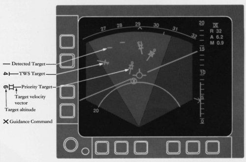
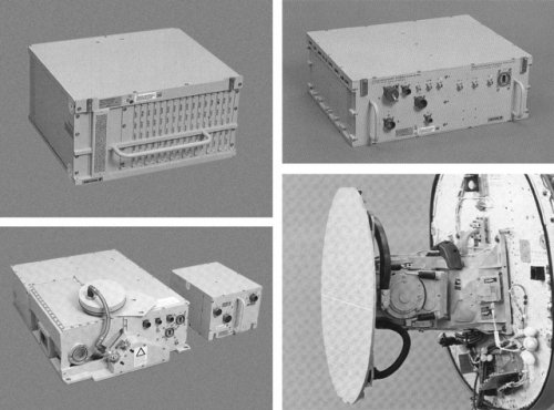
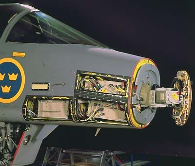
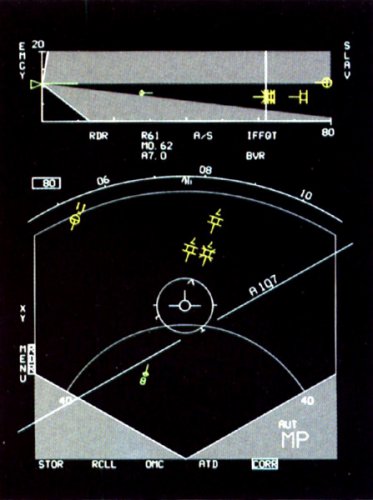
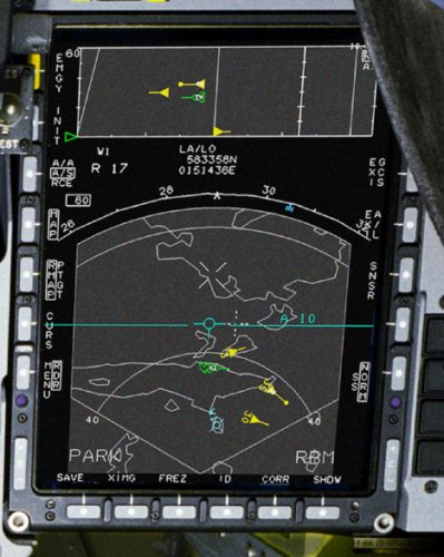
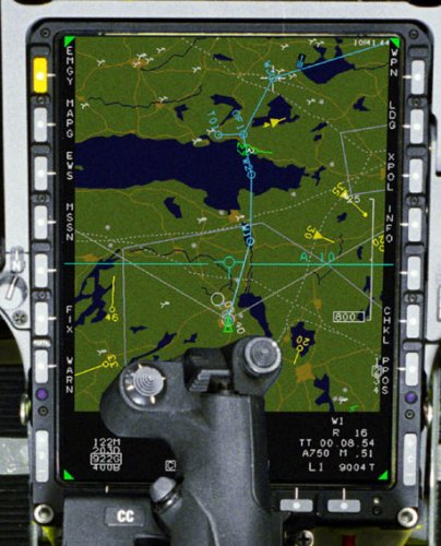


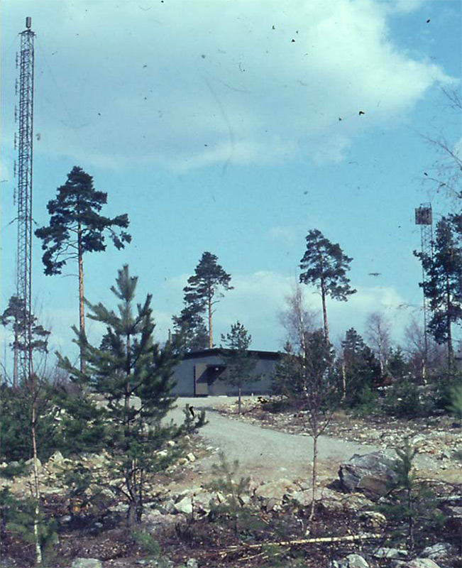


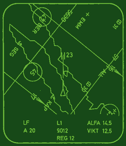


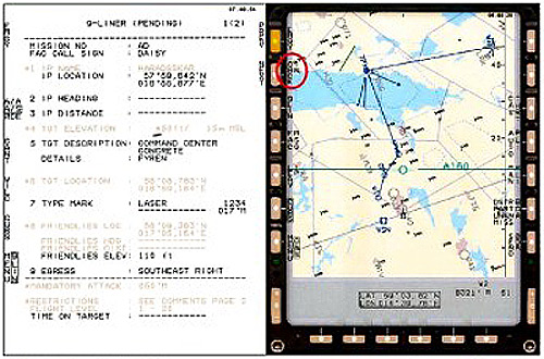


")