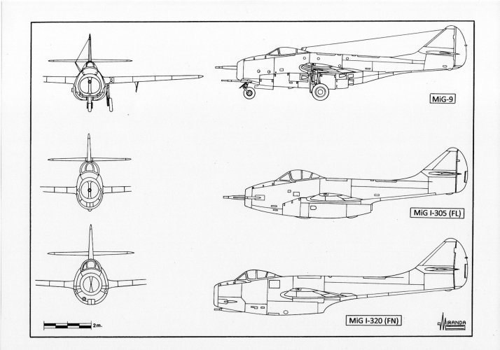
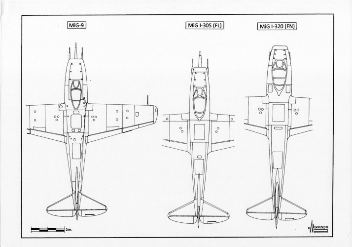
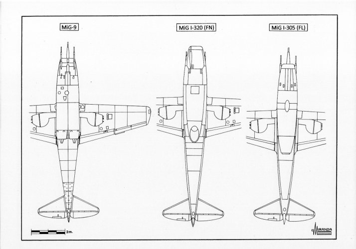
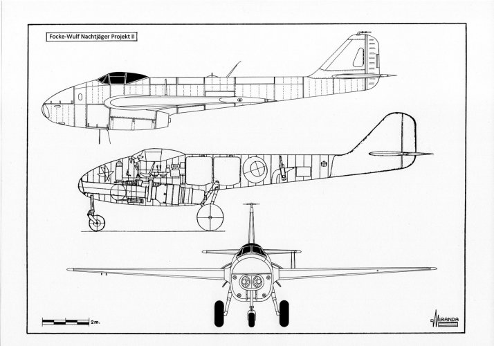
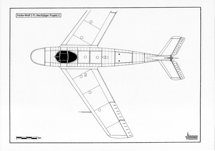
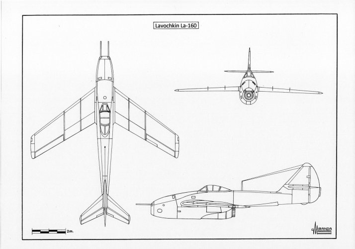
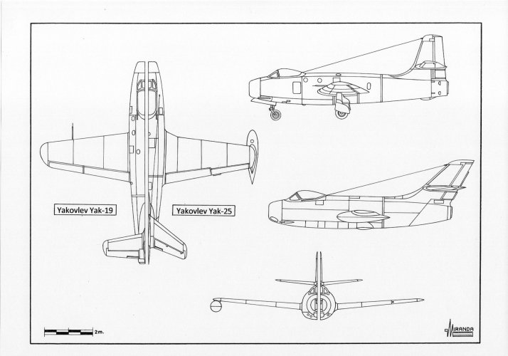
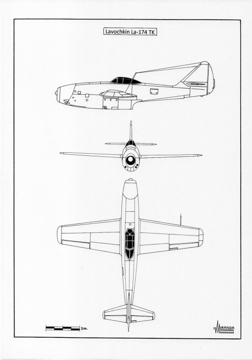
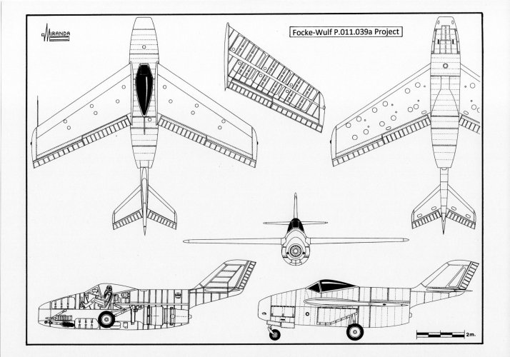
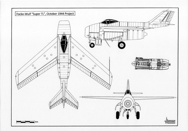
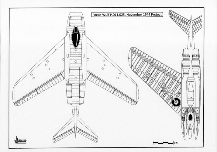
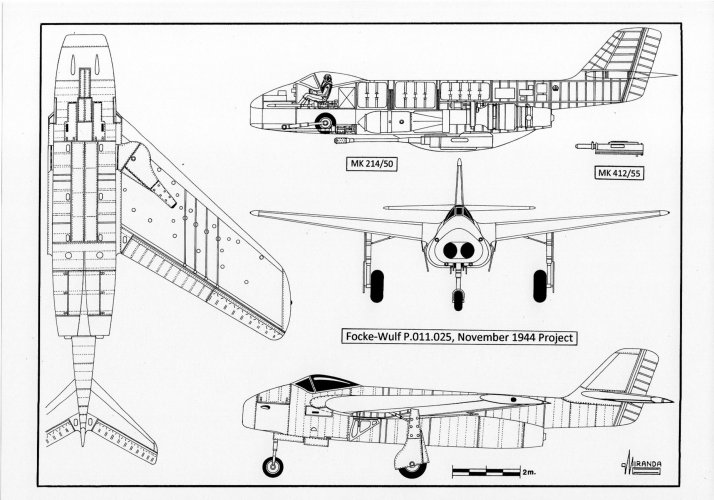
It cannot be ruled out that all these russian designs were influenced by the similar Focke Wulf concept.
By the end of the war the Western Powers had centrifugal turbojets with a thrust of 1,500 kg.
With the help of German scientists and engineers, the Soviets tried to develop the Jumo 004 H of 1,800 kg and the Jumo 012 with 2,700-2,900 kg thrust, but the technological step required several years of testing and development was stopped in 1948.
Work in the 3,400 kg thrust BMW 018 turbojet proved particularly difficult and several parts of the engine had to be redesigned from scratch in October 1946.
Therefore, they found themselves forced to design the first generation of Soviet jet fighters (Lavochkin La-150/152/174 TK and Yakovlev Yak-15/17/19) with the shortest possible air-intake ducts and tailpipes to minimize the jet power loss.
Early in 1943, the
Technisches Amt (RLM Technical Office) asked Messerschmitt if the Bf 109 G fighter could be adapted to take one Jumo 004 turbojet. The answer was negative.
In fact, the firm had all the necessary resources to comply with the RLM requirement: using the wing of the Me 209 and the nose wheel of the Me 309, it would only have been necessary to design a new central wing section so that the attachment points of the undercarriage would not interfere with the jet exhaust. But the
Sofortprogramm (interim solution) proposed by the RLM was contrary to the plans of Messerschmitt who at that time had already decided to continue the development of the Me 262. This situation gave the firm Focke-Wulf the opportunity to participate in the supplies of turbojets that until then had only been available for the Me 262 and the Arado Ar 234.
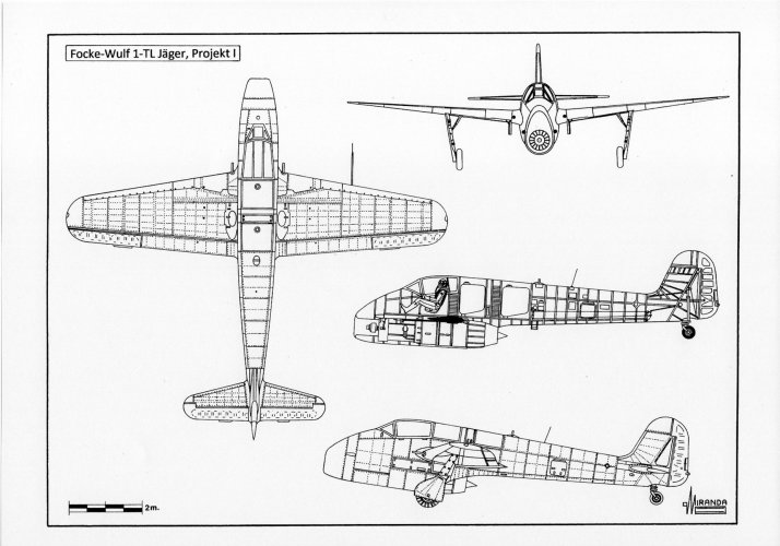
In February1943, the Bad Eilsen design team envisaged the study of several possible fuselage-turbojet-air intake configurations and their integration with different types of wings, tail surfaces and landing gears for the construction of a future single jet fighter. The simplest solution was to replace the BMW 801 radial engine of an Fw 190 by a Jumo turbojet, mounted under the nose, to not altering the position of the center of gravity of the aircraft. Unfortunately for the firm, the new engine turned out to be too long, so the jet nozzle would interfere with the retraction of the main wheels of the Fw 190. It was necessary to design a new type of wings capable of housing the mainwheels of 660 x 160 mm. The greater consumption of J2 heavy kerosene of the turbojet required the installation of two fuel tanks of 390 liters each in the fuselage, making necessary to advance the location of the cockpit by 170 cm.
It was planned to mount two Mauser MG 151/20 cannons in the wing roots and two Rheinmetall-Borsig MK 108/30 cannons under the cockpit floor. The
Projekt I was introduced to the OKL in March 1943 as a realistic solution that would have allowed the
Jagdwaffe to have an interceptor that would be faster than the
Mustang, better armed than the
Tempest and the
Meteor and able to overcome the
Thunderbolt in dive. It could have been mas manufactured by late 1944, but the
Technisches Amt rejected the project claiming that the position of the turbojet (whose axis was located 86 cm lower than that of the BMW 801) would substantially decrease the rolling properties, and it was feared that the Jumo 004 would suffer serious damage at belly landing. Also taken into consideration was the risk that jet exhaust gases would cause damage to the tailwheel or burn the airfield surface.
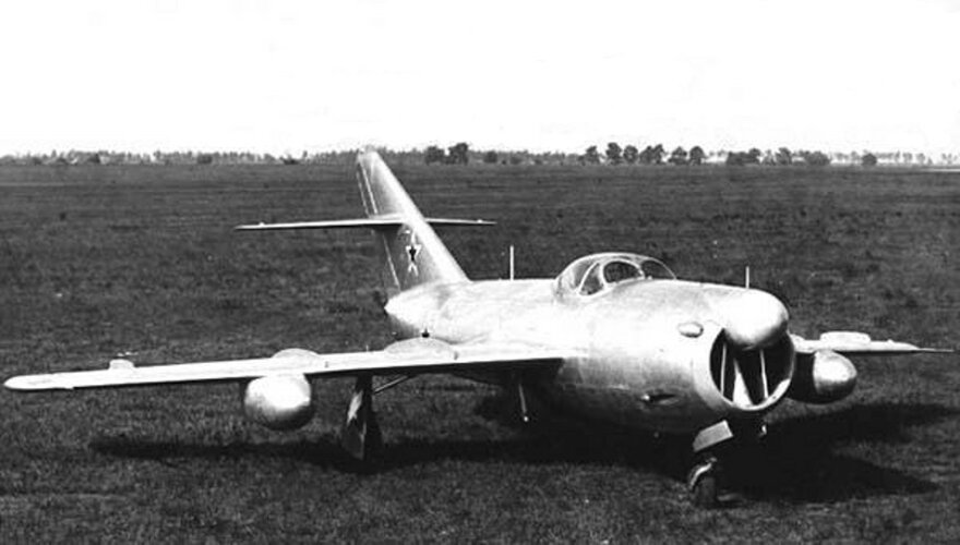
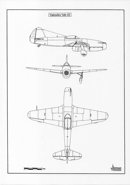
In response to a State Defence Committee requirement issued in February 18, 1945, for a 900 km/h pure jet fighter, the Soviets demonstrated with their stopgap jet fighter Yak-15 that German precautions were unfounded. The new Yakovlev fighter was based on the same formula as the
Projekt I and was powered by the same turbojet, being mass-produced, and entering into service in May 1947.
The integration of the turbojet in
redan (stepped) configuration with the airframe of a Yak-3 piston fighter was relatively simple. It was only necessary to modify the wing spar central section, replace the tailwheel with a steel roller, protected by a blast deflector, and to cover the lower part of the fuselage with steel plates.
Yak-15 technical data
Power plant: one Koliesov RD-10 turbojet rated at 900 kg static thrust, wingspan: 30.2 ft. (9.20 m), length: 28.5 ft. (8.70 m), height: 7.4 ft. (2.27 m), wing surface: 159.85 sq. ft. (14.85 sq. m), take-off weight: 6,029 lb. (2,735 Kg), maximum speed: 500 mph (805 km/h), service ceiling: 43,800 ft. (13,350 m), armament: two 23 mm Nudelman-Suranov NS-23 cannon in the top of the nose.
The Italians also used this aerodynamic solution in the Reggiane Re 2006 R project fighter and in the prototypes Ambrosini
Saggitario I (January 1953) and Aerfer
Saggitario II (May 1956).
Unfortunately for Lavochkin OKB it was not possible to use the same solution of the Yak-15 with the La-9 piston fighter because the wing structure and landing gear could not be easily modified to replace the ASh-82 FN piston engine with an RD-10 without making a major redesign of the airframe.
This was a major setback because all OKB-dependent production facilities were preparing to start the manufacturing, in October 1946, of a series of 1,630 La-9 conventional fighters at Gorky Plant No. 21.
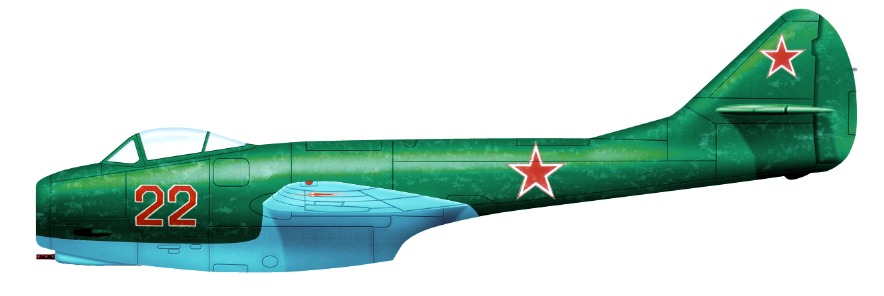
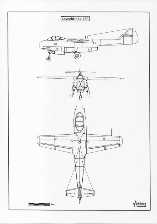
It was necessary to create the completely new design La-150 with shoulder wing, pod-and-boom configuration and the engine mounted behind the cockpit.
Some German features were adopted by Lavochkin: the nose air intake, the cockpit placed at the front of the fuselage and the fuselage-mounted, narrow-track, tricycle type landing gear, to avoid damaging runways, from the Focke-Wulf Ta 183 jet fighter project, the bifurcated air ducts from the Focke-Wulf Project P 011.025 (November 1944) jet fighter project and the bubble canopy from the Junkers Ju 248 V2 rocket fighter prototype captured at Kassel-Bettenhausen.
Fabrication of the La-150 prototypes had been delayed because the OKB was committed to other programs.
Five testing airplanes were built at Moscow Plant Nº 381 and the first of them was flown on September 11, 1946, reaching 546 mph (878 km/h), but it was not a success.
The aircraft showed many shortcomings during flight tests: duct power losses, high airframe weight, excessive oscillation of the tail surfaces caused by tail boom stiffness, lateral instability, and poor elevator forces.
A pre-series of 15 machines, with 25 per cent enlarged vertical stabilizer, were built at Gorky factory under the designation La-13 but their structural stiffness could not be overcome, and the La-150 development was stopped in December 1947.
Lavochkin La-150 technical data
Power plant: one Koliesov RD-10 turbojet rated at 900 kg static thrust, wingspan: 26.9 ft. (8.20 m), length: 39.9 ft. (9.42 m), height: 8.5 ft. (2.6 m), wing surface: 130.8 sq. ft. (12.15 sq. m), take-off weight: 6,528 lb. (2,961 Kg), maximum speed: 546 mph (878 km/h), service ceiling: 41,328 ft. (12,600 m), armament: two nose mounted 23 mm Nudelman-Suranov NS-23 cannon.
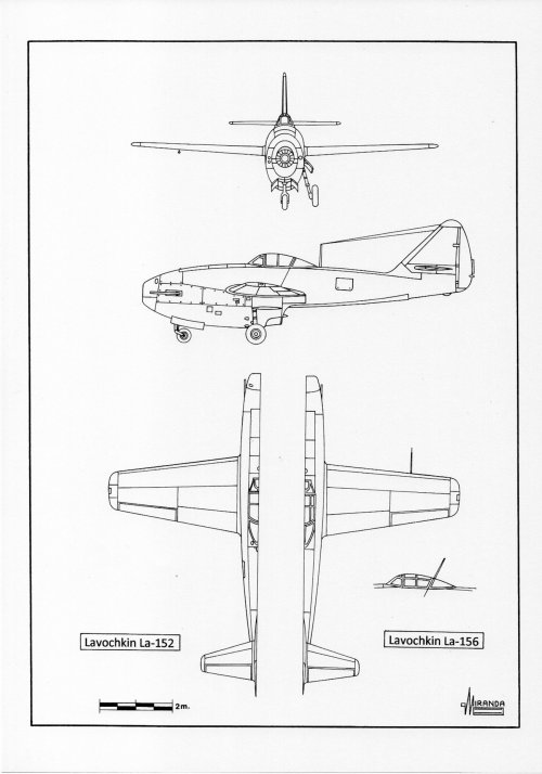
Designed in parallel with the La-150, the La-152 prototype was powered by one nose mounted RD-10 turbojet in
redan configuration. The 9.1 % thickness wing planform and tail surfaces were very similar to those of the La-150 but the mid-wing configuration and the folding-rearwards landing gear were based on those of the Messerschmitt P 1101 (February 22, 1945) and P 1106 (February 22, 1945) jet fighters projects.
The prototype was flown on December 5, 1946, reaching 522 mph (840 km/h) but crashed during state acceptance trials, on July 12, 1947, when the engine failed.
Lavochkin La-152 technical data
Power plant: one Koliesov RD-10 turbojet rated at 900 kg static thrust, wingspan: 26.9 ft. (8.20 m), length: 29.9 ft. (9.12 m), height: 11.4 ft. (3.48 m), wing surface: 130.8 sq. ft. (12.15 sq. m), take-off weight: 7,141 lb. (3,239 Kg), maximum speed: 522 mph (840 km/h), service ceiling: 35,105 ft. (10,700 m), armament: two nose mounted 23 mm Nudelman-Suranov NS-23 cannon.
The small size and light airframe of the Yak and Lavochkin proposals resulted in a performance that compared reasonably well with contemporary Western jet fighters, but their armament was inadequate to combat the B-29 bombers.
In February 1945, Pavel Sukhoi and Mikoyan Gurevich design bureaus were instructed to evolve a single seat heavy fighter of the Me 262 class around a pair of German turbojets.
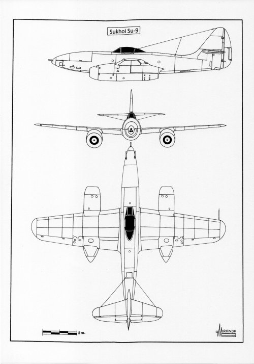
Owing to the urgency with which the program was attended, the Sukhoi Su-9 design, with two wing-mounted Jumo 004B turbojets, was very influenced by the Me 262 captured on March 30, 1945, and flight tested on August 15, 1945.
During the
Luftwaffe trials conducted at the end of 1942 with the Messerschmitt Me 262 V2 prototype, the high-altitude combat test program revealed unexpected compressibility effects during high-speed dives between 7,600 and 5,500 m. The Me 262 had been designed in 1940, before the aerodynamicists discovered the destructive effects associated with the transonic flux. The turbulent airflow generated in the junction between the engine nacelles and the wing undersurface generated some tailplane buffeting and elevator flutter.
Like its predecessors, Bf 110, and Me 210, the Me 262 proved to be an easy prey in dogfight against the single-engine Allied fighters, because the position of the engines considerably penalized their roll rate.
In September 1945 the Soviet Me 262 crashed during a high-speed dive test.
To circumvent the buffeting and poor roll rate problems, the MiG OKB-155 decided to use two BMW turbojets, placed very close together inside the fuselage, allowing it to fly using only one of them in case of failure, without lateral stability problems.
This aerodynamic solution also generated less drag than the Me 262 formula allowing the new I-300 (MiG-9) fighter to reach higher speeds.
It is at that time the scientists of the TsAGI did not yet have enough data to design swept wings as efficient as those of the Me 262 and the Soviet industry proved to be unable to build reverse engineered copies of the German wings.
Both Soviet fighters were designed with straight wings and tail surfaces and armed with one nose mounted 37 mm N-37, and two 23 mm NS-23 cannon, but the I-300 was tested with one nose mounted 57 mm N-57 cannon with a bulkhead in the intake, dividing the airflow to each turbojet.
German ground tests carried out in November 1944 showed that the internal drag in air ducts reduced the turbojet thrust by 45 kg for each meter in length.
To best profit of the scarce power available, the fuselage installation of the MiG-9 turbojets should have air-intake ducts and tailpipes as short as possible to minimize the jet power loss.
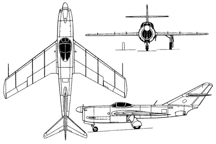
MiG OKB decided to incorporate into its design the mid-mounted straight wings, 27 degrees swept delta-style tailplane, tricycle undercarriage with the main gear retracting into the wings and ‘tadpole configuration’ used in the German night fighter project Focke-Wulf
Hochleistung Nachtjäger Projekt II (
Baubeschreibung Nr.251-251) from March 6, 1945.
The MiG-9 prototype was flight tested on April 24, 1946, reaching 572 mph (920 km/h) at 4,500 m. On July 11, 1946, the plane was destroyed as a result of tailplane structural failure.
The Su-9 prototype was flown on November 13, 1946, reaching 550 mph (885 km/h) but further development of the fighter was abandoned in favor of the MiG-9 series production.
Su-9 technical data
Power plant: two Koliesov RD-10 turbojets rated at 900 kg static thrust, wingspan: 36.8 ft. (11.21 m), length: 34.7 ft. (10.57 m), height: 12.2 ft. (3.72 m), wing surface: 217.87 sq. ft. (20.24 sq. m), take-off weight: 14,065 lb. (6,380 Kg), maximum speed: 550 mph (909 km/h), service ceiling: 42,000 ft. (12,800 m), equipment: one Heinkel
Kartusche ejector seat.
MiG-9 technical data
Power plant: two Kuznetsov RD-20 turbojets rated at 850 kg static thrust, wingspan: 32.8 ft. (10 m), length: 32.2 ft. (9.83 m), height: 10.6 ft. (3.23 m), wing surface: 202.2 sq. ft. (18.20 sq. m), take-off weight: 10,956 lb. (4,963 Kg), maximum speed: 572 mph (920 km/h), service ceiling: 44,280 ft. (13,500 m).
In April 1945 a special commission from the People´s Commisariat of the Aviation Industry flew to Berlin for examine German technical advances in the field of Aviation.
At the home offices of RLM, OKL and DVL institute, the Soviets had access to the technological secrets of the latest Focke-Wulf designs, when scored a complete set of Ta 183 blueprints, several scale models of the Ta 183 A-0 and many valuable technical documents of swept wing research by professors Goethert and Ruden.
Several DVL employees, including its head professor Bock, were interrogated, providing valuable information about wind tunnel tests performed with swept wings at critical Mach numbers.
In the autumn of 1945, Kurt Tank met with representatives of the GPU (Soviet Military Intelligence) who invited him to continue the development of the Ta 183 jet fighter in the USSR.
Especially interesting to Soviets was the design of the Ta 183 constant chord swept wing because it could be manufactured in wood/plywood, contain fuel and reach transonic speeds.
In addition, this type of wing performed well at low speeds without the installation of the leading edge automatic slats of the Messerschmitt designs that were very difficult to reproduce with Soviet manufacturing techniques.
On September 1947 the prototype La-156 reached 562 mph (905 km/h) powered by one RD-10F turbojet, with afterburning. But on January 28, 1948, the airplane was rejected during state acceptance trials because longitudinal instability and control problems.
Lavochkin La-156 technical data
Power plant: one Kazan RD-10F turbojet rated at 1,100 kg static thrust, wingspan: 28 ft. (8.52 m), length: 29.9 ft. (9.12 m), height: 11.4 ft. (3.48 m), wing surface: 142.4 sq. ft. (13.24 sq. m), take-off weight: 7,762 lb. (3,521 Kg), maximum speed: 562 mph (905 km/h), service ceiling: 41,328 ft. (12,600 m), armament: two nose mounted 23 mm Nudelman-Suranov NS-23 cannon.
During January 1946 the State Defence Committee issued a specification for a high-altitude interceptor with Mach 0.9 top speed and 30,000 ft. service ceiling.
A high-speed variant of the La-156 was fitted with 35-degree (25% chord-9.5% thickness) swept wings and a 44-degree swept tailplane based on those of the Focke-Wulf Ta 183 A-0 (October 1944) project.
The prototype, named La-160, was flown on June 24, 1947, powered by one RD-10 turbojet. After initial trials the aircraft was fitted with one RD-10 F engine, ejector seat and two boundary layer fences on each wing to overcome the problems of span wise flow. These anti-turbulence devices were patented by the Dipl. Ing. Wolfgang Liebe in 1938 after testing on the Messerschmitt Bf 109 B.
The La-160 reached a post-dive speed of 659 mph (1,060 km/h-Mach 0.92) flying at 5,700 m. but the transonic research program came to an end when the prototype disintegrated in September 1947 during a high-speed run, due to severe wing flutter.
Lavochkin La-160 technical data
Power plant: one Kazan RD-10F turbojet rated at 1,100 kg static thrust, wingspan: 29.3 ft. (8.95 m), length: 33 ft. (10.07 m), height: 12.9 ft. (3.9 m), wing surface: 171.15 sq. ft. (15.9 sq. m), take-off weight: 8,951 lb. (4,060 Kg), maximum speed: 659 mph (1,060 km/h), service ceiling: 36,080 ft. (11,000 m), armament: two nose mounted 23 mm Nudelman-Suranov NS-23 cannon.
The Yak-19 had been designed on June 15, 1946, with pod-and-boom configuration, 12% thickness laminar flow wing and RD-10 engine, but in late June 1946 the project was modified with an RD-10F engine. To meet the January 1946 specification, it was necessary to redesign the fuselage with a more aerodynamically efficient "flying stovepipe" configuration to install the afterburner under the tailfin.
The prototype was flown on January 8, 1947, reaching 564 mph (907 km/h) but the project was cancelled on August 21, 1947, due to problems experienced with the afterburner and the roll control.
Yak-19 technical data
Power plant: one Kazan RD-10F turbojet rated at 1,100 kg static thrust, wingspan: 28.5 ft. (8.7 m), length: 27.4 ft. (8.36 m), height: 10.9 ft. (3.3 m), wing surface: 145.3 sq. ft. (13.50 sq. m), take-off weight: 6,724 lb. (3,050 Kg), maximum speed: 564 mph (907 km/h), service ceiling: 39,600 ft. (12,100 m), armament: two nose mounted 23 mm
Sh-23 cannon, equipment: ejector seat.
To meet the April 1946 specification issued by the Council of People’s Commissars, calling for a jet fighter powered by the indigenous Lyulka turbojet, the prototype La-154 was to have been fitted with one TR-1 engine, but it was abandoned in 1947 because this engine was not considered safe for use in single engine fighters. The integration program was assigned to the development of the heavy fighters Sukhoi Su-11 and Alekseyev I-211.
MiG OKB decided to build a lighter version of the MiG-9 powered by only one turbojet.
It was expected to be able to use one Lyulka TR-1A rated at 1,500 kg in the prototype I-305/FL and a reheated variant, with 2,000-2,500 kg thrust in the MiG-9 FL series version.
The prototype was completed at the end of 1947, but the Lyulka exploded on the test bench and the FL project was discontinued.
MiG I-305/FL technical data
Power plant: one Lyulka TR-1A turbojet rated at 1,500 kg static thrust, wingspan: 32.8 ft. (10 m), length: 31.8 ft. (9.70 m), height: 10.8 ft. (3.20 m), wing surface: 202.2 sq. ft. (18.20 sq. m), take-off weight: 10,088 lb. (4,570 Kg), estimated maximum speed: 557 mph (897 km/h), estimated service ceiling: 43,952 ft. (13,400 m), equipment: pressurized cockpit and ejector seat.
Following the failure of the Soviet Lyulka VRD-3, TR-1 and TR-1A turbojets and the difficulties encountered by the Soviet industry in obtaining reverse-engineered copies of German turbojets, on June 17, 1946, the Council of People’s Commissars ordered the purchase of ten Rolls-Royce
Nene Mk.I and ten Rolls-Royce
Derwent V British turbojets.
In the middle of July 1946, the Soviet Union placed an order for these engines together with:
-Practical assistance.
-Training of Soviets engineers in jet engine assembly, operation, maintenance, and repair.
-Manufacturing licences, including high-grade, high-temperatures metallurgic process of Nimonic 75-80 alloys used to make turbine blades and discs.
The engines were delivered between March and July 1947 and the USSR ordered a second batch of twenty
Derwents, ten
Nene Mk.I and five
Nene Mk.II to be delivered in November.
A third batch of four
Derwents and twenty
Nenes were ordered at the end of year.
The British government did not granted manufacturing licenses but Klimov GAZ 116 started the mass production of unlicensed copies under the codenames RD-45 (
Nene Mk.I with 2,230 kg thrust), RD-45F (
Nene Mk.II with 2,270 kg thrust) and RD-500 (
Derwent V with 1,590 kg thrust).
On March 11, 1947, the Council of People’s Commissars ordered to Lavochkin, Yak and MiG bureaus the development of two new fighters powered by British turbojets: one general-purpose tactical fighter with 950 km/h top speed and
Derwent engine and one high-altitude Mach 0.9 interceptor with
Nene turbojet.
Each OKB proposed two versions of each model: one with straight wings and pod-and-boom configuration and another with swept wings and "flying stovepipe" configuration.
March 11, 1947, tactical fighter development:
In an attempt to improve the performance of the La-156, a thin wing version was built with a thickness ratio of only 6 per cent and 200 kg less weight.
The new prototype, named La-174 TK, was flown in January 1948, reaching 603 mph (970 km/h).
Lavochkin La-174 TK technical data
Power plant: one Roll-Royce
Derwent V turbojet rated at 1,590 kg static thrust, wingspan: 28.3 ft. (8.64 m), length: 30.9 ft. (9.41 m), height: 12 ft. (3.7 m), wing surface: 145.53 sq. ft. (13.52 sq. m), take-off weight: 7,308 lb. (3,315 kg), maximum speed: 603 mph (970 km/h), service ceiling: 44,280 ft. (13,500 m), armament: three nose mounted 23 mm Nudelman-Suranov NS-23 cannon.
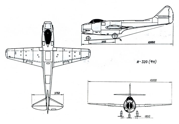
Late in 1947 a production MiG-9 was modified replacing the two RD-20 turbojets with one
Nene Mk.I.
To accommodate the new centrifugal engine of 1,257 mm of diameter it was necessary to redesign the fuselage but the project, named I-320/FN (a project without any connection with the I-320 R-1 night fighter) was cancelled in favor of the new I-310 S swept wing prototype.
MiG I-320/FN technical data
Power plant: one Rolls-Royce
Nene Mk.I turbojet rated at 2,230 kg static thrust, wingspan: 32.8 ft. (10 m), length: 35.7 ft. (10.88 m), height: 10.76 ft. (3.23 m), wing surface: 202.2 sq. ft. (18.20 sq. m).
The Yak-23 was a follow-on of the Yak-15, with
redan configuration and tricycle undercarriage, powered by one nose mounted
Derwent V turbojet.
The prototype was flown on July 8, 1947, reaching 575 mph (925 km/h).
The Yak-23 was built, as a tactical fighter, on a series of 316 machines between 1948 and 1951.
Yak-23 technical data
Power plant: one Rolls-Royce
Derwent V centrifugal turbojet rated at 1,590 kg static thrust, wingspan: 28.6 ft. (8.73 m), length: 26.7 ft. (8.13 m), height: 10.8 ft. (3.31 m), wing surface: 145 sq. ft. (13.5 sq. m), take-off weight: 7,460 lb. (3,384 kg), maximum speed: 575 mph (925 km/h), service ceiling: 48,600 ft. (14,800 m), armament: two nose mounted 23 mm NR-23 cannon, equipment: ejector seat.
The Yak-25 was an improved variant of the Yak-19, with "flying stovepipe" configuration, 9% thickness straight wing and 45-degree swept back tail surfaces, powered by one
Derwent V turbojet.
The prototype was flown on October 31, 1947, reaching 610 mph (982 km/h) but the project was discontinued on July 1948 due to extremely severe tail buffeting.
Yak-25 technical data
Power plant: one Rolls-Royce
Derwent V centrifugal turbojet rated at 1,590 kg static thrust, wingspan: 29.1 ft. (8.88 m), length: 28.3 ft. (8.65 m), height: 11.87 ft. (3.62 m), wing surface: 150 sq. ft. (14 sq. m), take-off weight: 7,022 lb. (3,185 kg), maximum speed: 610 mph (982 km/h), service ceiling: 46,000 ft. (14,000 m), armament: two nose mounted 23 mm NR-23 cannon, equipment: ejector seat.
March 11, 1947, high-altitude interceptor development:
When it became apparent that the reheated Lyulka TR-2 with 2,500 kg thrust was not going to be available, the MiG I-305/FL was completely redesigned to reduce the weight to a maximum of 4,500 kg.
To meet the March 11, 1947, specification the airplane received the project designation I-310 S.
The I-310 S initial project was expected to be powered by an RD-10F, but as British centrifugal turbojets became available, it was necessary to redesign the fuselage with a diameter of 1,512 mm.
Having the excess power generated by the new British turbojets, the Soviet designers were able to abandon the pod-and-boom system and build lighter fuselages with the same tubular structure of the Junkers Ju 248, already tested on the MiG I-270.
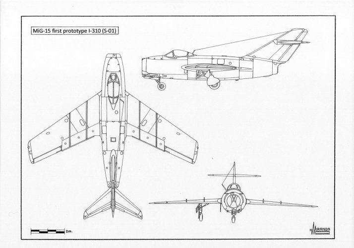
The MiG I-310 S had mid-mounted wings with 35-degree swept (25% chord), 2-degree anhedral, fitted with fences to delay the migration of the pressure center at high speed, 55.7-degree swept tailfin, 40-degree swept mid-high tail plane and nose mounted bubble canopy.
The prototype I-310 S-01 was flown on December 30, 1947, powered by one Rolls-Royce
Nene Mk.I and was cleared for mass production, under the designation MiG-15, at State Aircraft Factory I.
MiG I-310 S-01 technical data
Power plant: one Roll-Royce
Nene Mk.I centrifugal turbojet rated at 2,230 kg static thrust, wingspan: 33 ft. (10.08 m), length: 33.1 ft. (10.10 m), height: 12 ft. (3.7 m), wing surface: 228.8 sq. ft. (20.6 sq. m), take-off weight: 10,640 lb. (4,820 kg), maximum speed: 648 mph (1.042 km/h), service ceiling: 49,856 ft. (15,200 m), armament: two nose mounted 23 mm Nudelman-Suranov NS-23 cannon and one 37 mm N-37 cannon.
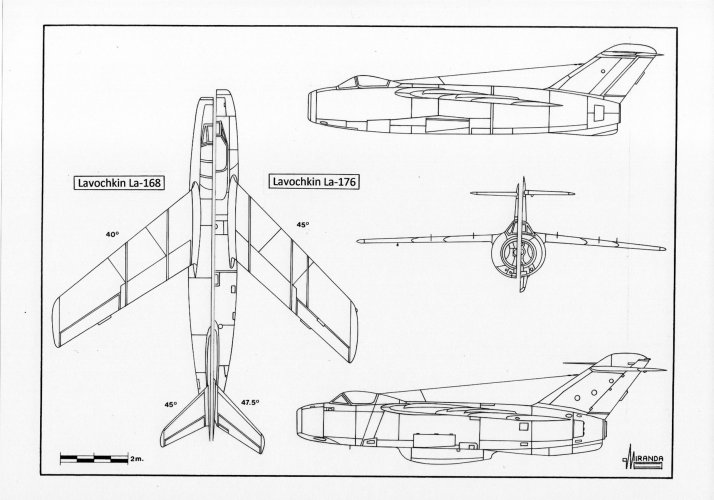
The Lavochkin La-168 prototype flew on April 22, 1948, reaching 1,084 km/h-Mach 0.914.
The new plane was fitted with 37-degree swept wings, 45-degree T-tail plane and fuselage mounted landing gear.
The La-168 was a better performing aircraft than the I-310S but its narrow track landing gear was not considered suitable for rough-field operations.
Lavochkin La-168 technical data
Power plant: one Roll-Royce
Nene Mk.I centrifugal turbojet rated at 2,230 kg static thrust, wingspan: 31.2 ft. (9.5 m), length: 34.6 ft. (10.56 m), height: 11.47 ft. (3.5 m), wing surface: 194.6 sq. ft. (18.08 sq. m), take-off weight: 10,097 lb. (4,580 kg), maximum speed: 674 mph (1.084 km/h-Mach 0.914), service ceiling: 42,650 ft. (13,000 m), armament: two nose mounted 23 mm Nudelman-Suranov NS-23 cannon and one 37 mm N-37 cannon.
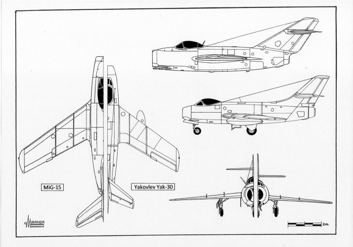
The Yakovlev response to the March 11, 1947, requirement was the Yak-30, an advanced version of the Yak-25 with 35-degree swept wings and 35-degree tailplane.
The prototype was flown on September 4, 1948, reaching 659 mph (1,060 km/h) powered by one
Derwent V turbojet.
Factory testing concluded on December 16, 1948.
Yak-30 technical data
Power plant: one Roll-Royce
Derwent V centrifugal turbojet rated at 1,590 kg static thrust, wingspan: 28.4 ft. (8.65 m), length: 29 ft. (8.86 m), height: 11.55 ft. (3.52 m), wing surface: 161.5 sq. ft. (15 sq. m), take-off weight: 7,286 lb. (3,305 kg), maximum speed: 659 mph (1.060 km/h), service ceiling: 49,200 ft. (15,000 m), armament: two nose mounted 23 mm Nudelman-Suranov NS-23 cannon and one 37 mm N-37 cannon.
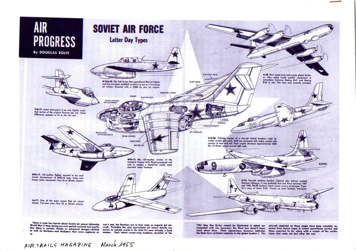
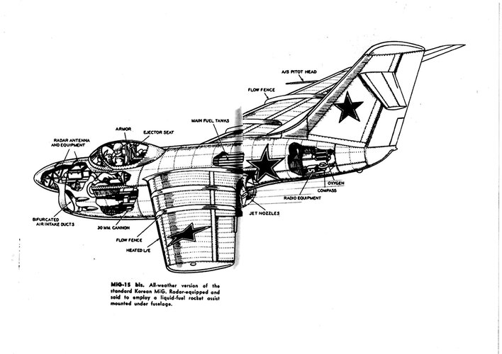
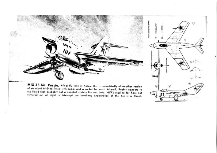
During the Korean War around ten B-29 bombers and two RB-29 reconnaissance airplanes were downed by MiG-15 bis night fighters.
The UN pilots believed in some cases the MiG’s had AI radar (and this leaked to US press at the time) but there was no ELINT backing up such claims.
The Soviets did not use AI radars in the Korea War, all intercepts were done with help of GCI ground radar. The MiG-15 bis day interceptors were guided by the P-20
Periscop (
Bar Lock) radar network until they could locate the bombers, with the help of searchlights or moonlight, and they attacked them using the
Wilde Sau tactics developed by the
Luftwaffe in 1943.
The B-29 bombers could be located by emissions from their H2X cartographic radars and IFF transponders and using the SHORAN navigation system which made their approach routes predictable.
Late in the war, a few MiG’s were fitted with experimental infra-red detectors based in the German IR seeker Zeiss FuG 280
Kiel Z.
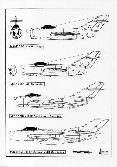
In 1950 the prototype MiG-15P bis (SP-1) was flight tested with the experimental radars
Toriy, and
Toriy-A. All of them were equipped with a parabolic antenna which performed both search and tracking function.
The system proved to be too complicated to be used in combat because the antenna was operated manually for tracking the target.
The MiG-15P bis (SP-5) was a parallel development equipped with
Korshun AI radar, it used two antennas for search and automatic tracking.
In 1958 a small series of five aircraft was built with the new RP-1
Izumrud-1 (
Scan Odd) AI radar. These aircraft were used to develop new night combat tactics for the MiG-17P (SP-7) all-weather interceptor.
There is no evidence that any of these prototypes were used in Korea.
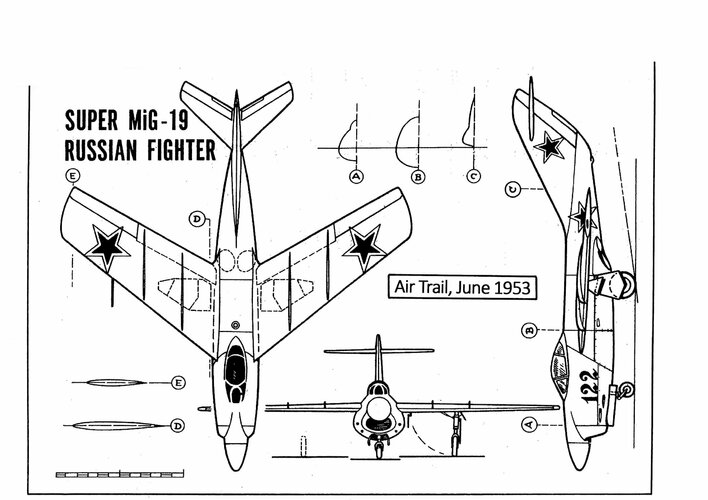
When the USSR revealed the MiG-15, during the May 1949 parade, Western analysts noted that it strongly resembled the German Focke-Wulf Ta 183 A-0 jet fighter project.
Many Western books and magazine articles stressed the similarity of both designs and they assumed that the general aerodynamic layout of the MiG was influenced by German designs.
Perhaps the Soviets had continued to develop the Ta 183 after the war, as they did with the Junkers Ju 248, EF 126, EF 127, EF 131, DFS 346 and the Heinkel He 343/Ilyushin Il-22 projects.
Why not?
The USSR was within its rights to use the technology conquered with the sacrifice of its soldiers.
The importance of the German scientific and technological achievements was well understood both in the USSR and in other countries.
After the war ended, the Allied powers raced to seize aeronautic technology in occupied Germany and the aerodynamic configuration of these German projects, proof-of-concept prototypes, weapons, and operational airplanes were used in the first generation of the Cold War jet fighters.
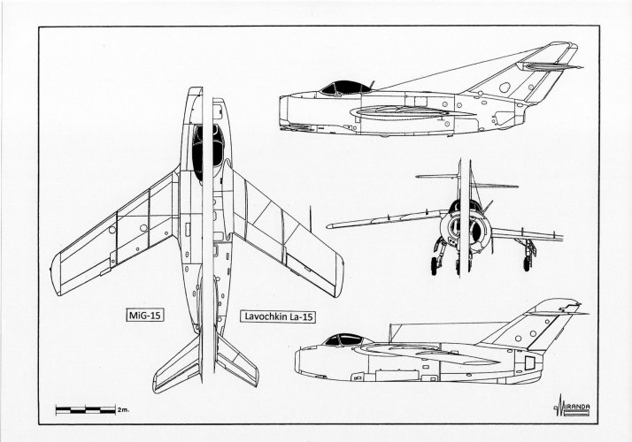
The nose air intake/tubular fuselage/rear swept wings and tail surfaces configuration of the Messerschmitt P.1101 and Focke-Wulf Ta 183 fighters were used in North American F-86
Sabre, MiG-15
Fagot, MiG-17
Fresco, Lavochkin La-15
Fantail, Dassault MD 450
Ouragan, Dassault MD 452
Mystère, Nord 2200, Tank IAE 33
Pulqui II, Fiat G.91
Gina and Fuji T-1.
The delta wing configuration of Lippisch DM-1 and Messerschmitt P.1112/S2 was used in the Convair XF-92, Convair F-102, Nord 1402
Gerfaut, Sud-Est S.E. 212
Durandal, Dassault
Mirage I, Avro 707, Boulton Paul P.111, Boulton Paul P.120, Handley Page H.P.115, Fairey
Delta 1, Fairey
Delta 2, BAC 221 and Short SC.1.
The maximum speed of the first prototypes XF-92 and YF-102 was limited to 0.98 Mach, due a transonic drag much higher than expected, but the problem was solved in December 1954 using the aerodynamic principle named
area rule, patented by Junkers on March 1944.
Swept wings with two trailing-edge fins configuration from Arado E.583 and Junkers EF.128 projects was used in the Chance Vought F7U
Cutlass naval fighter.
The “bat wing” of the Messerschmitt Me P.1109-01 and Blohm und Voss P.208 projects was used in 1996 in the prototype Boeing
Bird of Prey.
The oblique
scissors wing of the Messerschmitt Me P.1109-01 and Blohm und Voss P.202 projects were flight tested in 1979 with the NASA Ames AD-1 research airplane.
The forward-swept wing of the German projects Heinkel He 162 B, Blohm und Voss P.209.02, BMW
Strahlbomber II, and Focke-Wulf P. 03028, was flight tested with the Grumman X-29 research plane in 1984.
The butterfly tailplane of the Heinkel P.1079A and Messerschmitt P.1110 projects were used in 1951 in the Supermarine Type 508 prototype and in the Fouga CM.170
Magister jet trainer in 1952.
The
Versuchsflugel II crescent wing of the Arado Ar 234 V16 project was used in the Handley Page H.P.88 research plane in 1951 and in the Handley Page
Victor strategic bomber in 1952.
The tailless configuration of the Messerschmitt Me 163
Komet was flight tested in the research planes de Havilland D.H.108 in 1946, Northrop X-4 in 1948, Payen
Katy in 1954 and in the Douglas F4D
Skyray naval fighter in 1951.
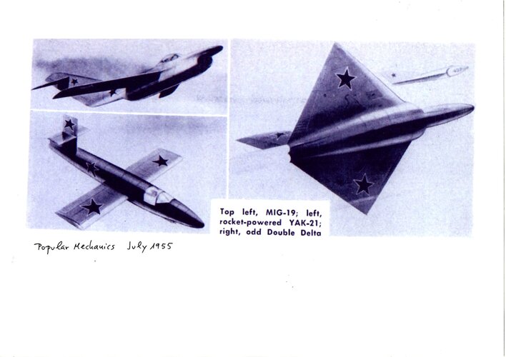
The double-delta configuration of the Henschel P.130 project was used by SAAB in their J35
Draken jet interceptor in 1955.
The jet/rocket mixed propulsion system of the Messerschmitt prototype Me 262 V074 and the Focke-Wulf Projekt VI
Flitzer were used in the French interceptor Dassault
Mirage IIIC in 1961 and in the British research airplane Saunders-Roe S.R. 177 in 1947.
The variable-geometry wing of the Messerschmitt P.1102-05 was used in the Bell X-5 and
Mirage G prototypes, in the Grumman F-14
Tomcat naval fighter, in the MiG-23 fighter-bomber and in the Panavia
Tornado bomber.
The radar rotating antenna of the airborne early warning airplanes Grumman E-2
Hawkeye and the AWACS Boeing E-3
Sentry, was developed in 1944 for the Arado Ar 234 C-3, to track a bomber stream up to distances of 45 km, using a FuG 244
Bremen 0 radar set with a rotating disc above the fuselage.
The heat-seeking missile AIM-9
Sidewinder and the Soviet copy R-13/AA-2
Atoll were based on the infrared homing devices and infrared proximity fuses developed by AEG and Kepka for the German missiles Messerschmitt
Enzian, Henschel Hs 117
Schmetterling, EMW
Wasserfall and Ruhrstahl-Kramer X-7
Rotkäppchen.
The annular wing developed by von Zborowski for the Heinkel
Wespe VTOL project, was flight tested in 1958 with the French prototype SNECMA
Coléoptère.
The French DEFA and British ADEN 30 mm cannon were developed from the German Mauser MG 213C.
The USAAF 0.60-caliber heavy machine gun was a straight copy of the German Mauser MG151.
The
Mighty Mouse air-to-air unguided rockets fired by the all-weather interceptors Lockheed F-94
Starfire, Northrop F-89
Scorpion and North American F-86 D
Sabre Dog during the Cold War, were developed from the Rheinmetall R4M
Orkan 55 mm rocket, and their automatic firing radar system probably was a development of the German FuG 222
Pauke S fire control radar with
Oberon-Elfe predictor system.
The ramjet propulsion of the German projects Lippisch P.13a, Skoda-Kauba SK P.12, Heinkel P.1080, Focke-Wulf Ta 283 and Messerschmitt P.1101L was flight tested by the North American F-51D c/n 44-63528 in 1946, the Lockheed F-80
Trijet in 1948, and the French prototypes Leduc 021 and Sud-Ouest SO 9000
Trident in 1953.
The turboprop configuration of the Focke-Wulf P.0310226-17 project was flight tested in 1953 with the McDonnell XF-88B prototype, and by the Republic XF-84 H
Thunderscreech research plane in 1955.
The canard fore planes of the Blohm und Voss P.217 and Messerschmitt P.1110 (Feb 12, 1945) projects were used by the Dassault
Mirage Milan in 1969.
Several versions of the Fieseler Fi 103 (V-1) cruise missile were manufactured in USA, as Republic-Ford JB-2
Loon, in France as ARSAERO CT-10 and in the USSR as the Izdeliye 10.
The EMW V-2 ballistic missile was manufactured in the USSR as the R-1 in 1948, in USA as RTV-G-4
Bumper and developed as the PGM
Redstone rocket of the NASA
Mercury project in 1958.
The Rheinmetall-Borsig
Rheintochter surface-to-air missile concept inspired the Soviet SA-2 (1958) and the US
Nike Ajax (1954).
The Doblhoff WNF 342 jet propelled rotor concept was used in the Hiller YH-32
Hornet helicopter in 1950, in the XH-26
Jet Jeep helicopter in 1952, in the Fairey
Rotodyne compound gyroplane in 1957 and in the Fairey
Gyrodyne prototype in 1957.
The SNECMA
Atar 101 French turbojet was developed from the BMW 003 axial-flow turbojet.
However, the MiG-15 seems to be a special case. Over the past 72 years respected authors have published numerous works denying the Focke-Wulf heritage of the Soviet fighter and detailing the differences between the two designs.
They are certainly right about the Ta 183 A-0
Huckebein, which is the version best known for having won the
Jägernottprogramm contest.
But the information captured in Berlin about the latest projects of the Bad Eilsen design team comprised eleven variants of the Ta 183 and nine scaled-up and scaled-down associated designs that shared the original basic aerodynamic layout.
These projects differed in the position of the wings (shoulder, mid and low) and tail planes (T, mid and low), had different wings with swept angles between 33 and 43 degrees, tail planes between 35 and 49 degrees swept, and tailfins between 41 and 67 degrees swept, at the leading edge in all cases. Most were equipped with fuselage retractable landing gear, but some retracted on the wings, such as the MiG-15.
The Soviet designers were able to adopt ideas from all of them by concentrating them in a single project.
The fuselage of the MiG-15 (built with
Podberezhye semi-monocoque Duralumin structure) and the pressurized cockpit were both based on those of the Junkers Ju 248 V2 captured at Kassel and the ejector seat was based on that of the Heinkel He 162 A-2 captured in Vienna.
The wings were a modification of those of the Lavochkin La-160, which were in turn based on those of the Focke-Wulf designs captured in Berlin by the People's Commisariat of the Aviation Industry, and joined the fuselage in the same position as those of the Junkers Ju 248 V2.
The wing retractable undercarriage and the 45-degree swept tailplane were very similar to those of project Focke-Wulf P.011.025 (November 1944).
The engine was a British design.
But, according to the Soviet designers, the MiG-15 was an indigenous design.
This is true in the sense that they had been able to integrate different German and British technologies into a design adapted to the Soviet manufacturing standards and that no German TsAGI technicians had been involved in this process.
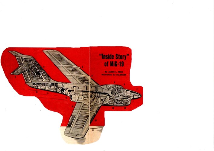
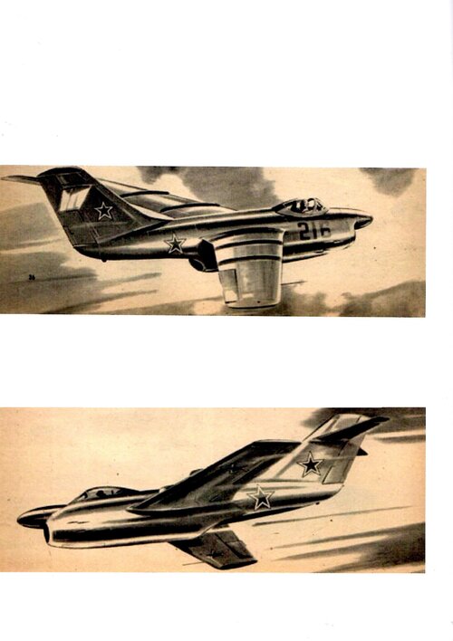
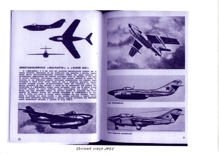
Ironically, the MiG OKB designers used Focke-Wulf T-tail planes on the MiG I-270 rocket fighter prototype and in the MiG-19 prototype SM-2/1, without success.
On July 15, 1944, the
Luftwaffe Technisches Amt (Technical Office) requested through
Proposal 222/I the design of an air superiority fighter, powered by a Heinkel HeS 011 A-0 turbojet, as part of the
Jägernottprogramm (emergency fighter program) contest.
The new aircraft should reach a maximum speed of 1,000 km/h at 7,000 m, with a service ceiling of 14,000 m, an armament of two MK 108/30 heavy cannons with 60 rounds per gun and a fuel capacity of 1,000 liters. A high proportion of
sparstoffe (non-strategic materials), such as steel, wood, and plastics, would be used for its construction.
The OKL ordered that large-scale production should start in February 1945 and reached a monthly production rate of 5,000 fighters in June. Initially the projects presented were the Blohm und Voss P.213.03, Heinkel P.1078 C, Junkers EF.128, Messerschmitt P.1101, P.1110/I and P.1111, as well as the Focke-Wulf Ta 183 A, Ta 183 B and
Flitzer III.
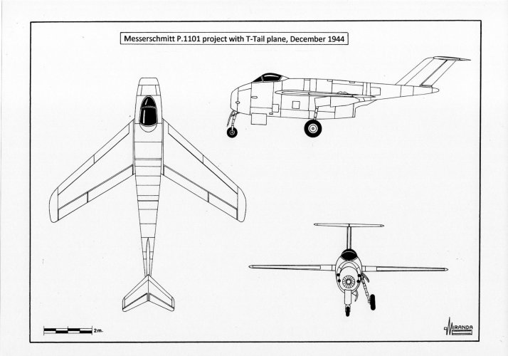
In October 1944 only two contestants remained: the Focke-Wulf Ta 183 A and the Messerschmitt P.1101, a pod-and-boom design theoretically capable of reaching transonic speed during combat diving without losing maneuverability. But the wind tunnel tests performed by the AVA-Göttingen institute during the autumn of 1944, with P.1101 scale models, revealed that the maximum speed would still be below their expectations.
The reason was the turbulence generated in the joint of the rear fuselage and the engine nacelle, that had an '8' shaped section. It was discovered that the airframe generated a triple shock wave at transonic speed. The first one was formed around the cockpit hood, the second over the wing and the third one over the tailplane. The shock waves overlapped among each other with a braking effect like that of an arrow going through three disks of felt launched in the air.
The Messerschmitt designers tried to solve the problem replacing the cockpit hood with another of low drag, type
Rennkabine, originally designed for a high-speed version of the Me 262. Wind tunnel tests performed with 'V' and 'T' shaped tail planes revealed that such modifications did not substantially improve aerodynamic performance and the P.1101 was cancelled at the end of 1944.
During the selection process, the Ta 183 A suffered numerous modifications that gave way to the Ta 183 A-0 version, winner of the contest. The wing chord was reduced from 252 to 235 cm and the wing area to 22.5 sq. m. The tailfin swept was of 60-degrees, the overall length of 9.2 m and the height of 3.5 m. The tailplane sweep angle was increased to 45-degrees and the ground incidence to 7-degrees.
The estimated maximum speed for this version was set at 960 km/h and the service ceiling at 14,400 m, with an initial climb rate of 20 m/sec.
The
Technisches Amt considered that the 40-degree (25% chord) swept wings of the Ta 183 were potentially dangerous during landing at low speeds. But most of the criticism of its experts were directed against the T-tail plane configuration. They argued that it was too heavy for a fighter, it did not provide enough lateral stability and could not be built on wood.
The T-tail plane was also too advanced for the mentality of the OKL (
Oberkommando der Luftwaffe-Air Command). Its main objection was based on the danger posed by the tailplane to a pilot attempting to bail out at high speed.
The ejector seat designed in 1942, to equip future versions of the Focke-Wulf Fw 190 piston fighter, could launch the pilot at a height of 2 m above the cockpit floor, with a margin of 43 cm over the tailfin. But the T-tail plane, designed to avoid the turbulent airflow generated by the cockpit hood at transonic speeds, had to be installed more than three meters high above the level of the cockpit floor to be effective.
The
Technisches Amt calculated that during an ejection at critical Mach number, the T-tailplane would reach the pilot in only 0.018 seconds. In 1944, the most effective ejector seat of the world was the
Heinkel Kartusche propelled by an explosive cartridge with 30 grams of powder, with an ejection speed of 11 m/sec and 12 g. It was designed for speeds not exceeding 700 km/h. At 1,000 km/h and using a T-tail plane it was necessary to increase the ejection speed to 200 g, with equally lethal effects for the pilot.
Coming ahead of the predictable objections of the
Technisches Amt, Kurt Tank designed a more conservative version as well, with reduced armament and a conventional tailplane. This new configuration, described in the dossier
Baubeschreibung Nr.252, was presented to the OKL at the same time than the project P.011.018a to avoid the total rejection of the project. Both designs received the official designation Ta 183, been described in the specialized literature as Ta 183-I/Ta 183 A and as Ta 183-II/Ta 183 B.
In February of 1944 Kurt Tank sent to the RLM (
Reichsluftfahrtministerium – Reich Ministry of Aviation) a set of drawings and calculations contained in the dossier denominated
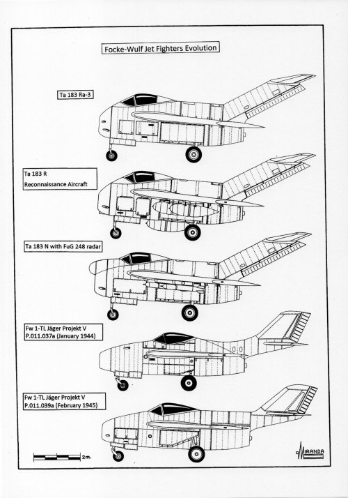
Baubeschreibung Nr.252 describing a ‘soft’ second iteration of the Ta 183, denominated Ta 183 B (P.011.037a).
The cross section of the fuselage was 24 per cent lower than that of the Ta 183 A, the armament was reduced to only two MK 108/30, the cockpit was moved backwards 1.5 m and the tail plane was placed at the same height as the head of the pilot. The wingspan was reduced by 50 cm and the sweep wing angle to 34-degree, the wing roots were moved to the rear by 90 cm and the tailplane was moved forward by 72 cm. The internal fuel capacity did not change.
This basic design evolved throughout 1944 trying to adapt to the changing demands of the
Jägernottprogramm. In its version P.011.039a (February 1945) the cockpit had been advanced 36 cm to improve the visibility of the pilot at landing, the wings had been advanced 11 cm to preserve the longitudinal stability, altered by the weight of the new fuel tank of 250 liters installed over the air duct.
The Ta 183 B was superior to all versions of the Ta 183 A in ceiling and maximum speed, thanks to its smaller front section and the lower structural weight of the airframe and surely this information was obtained by MiG designers through the captured German scientists.
In January 1948 the Soviet Council of Ministers issued a decree calling for a high-performance, long-range, all-weather fighter capable of mounting standing patrols and intercepting the Strategic Air Command bombers far from their targets.
The PVO staff estimated that to achieve this objective a plane with performances similar to those of the MiG-15 would be necessary.
But the fighter would also have to carry a large amount of fuel, a radar of 100 kg and a second crewmen.
To meet the conditions of the specification it would be necessary to use at least two RD-45F centrifugal engines rated at 2,270 kg thrust each, the best turbojet available at the time.
If installed under the wings of the new interceptor, both engines would have generated an unacceptable loss of speed owing to their rather large diameter of 1,273 mm.
Nor would it have been aerodynamically effective to install them under the fuselage belly in side-by-side configuration.
The American long range fighter Bell XP-83 built in 1944 with this basic configuration it had to be canceled due to its poor performance.
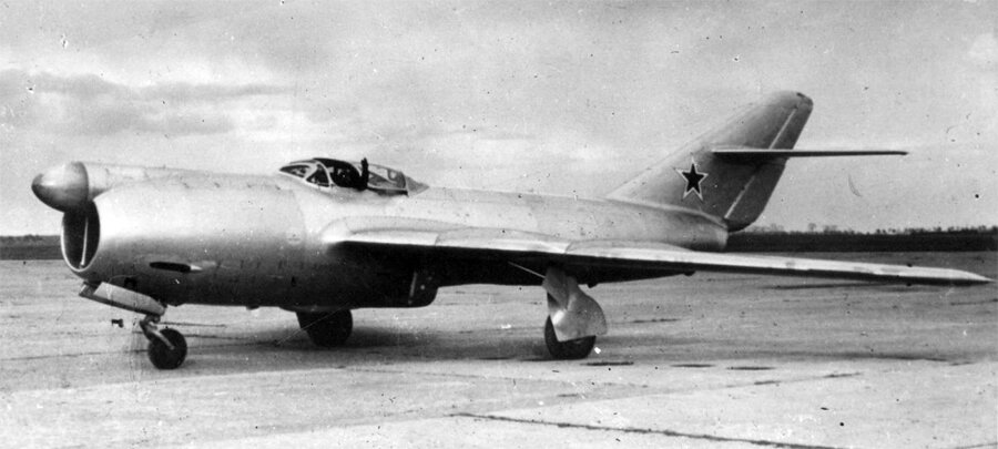
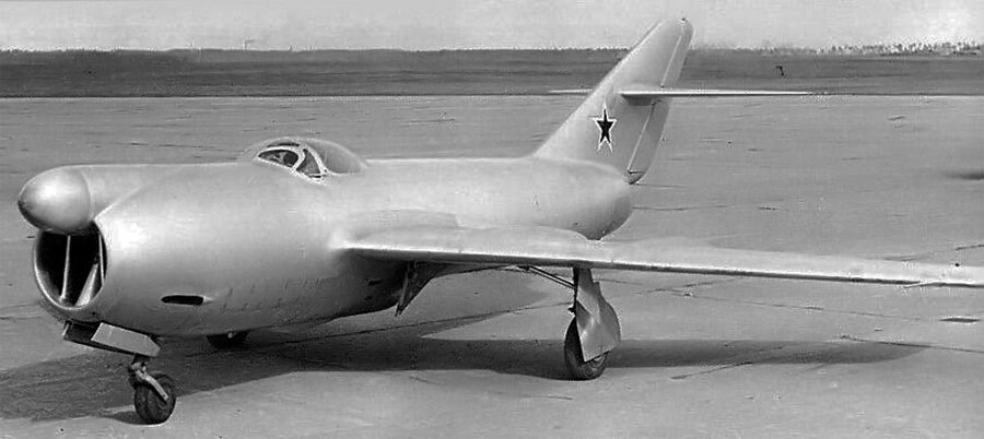
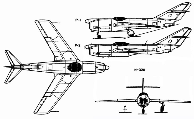
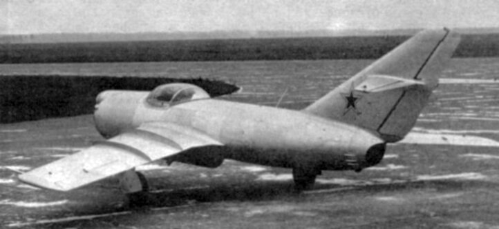
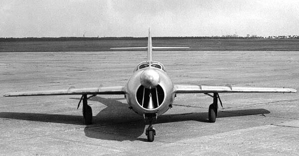
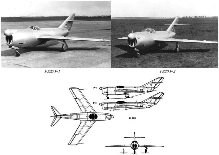
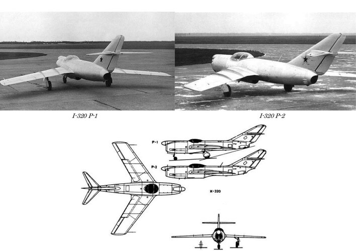
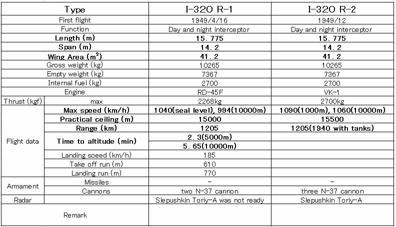
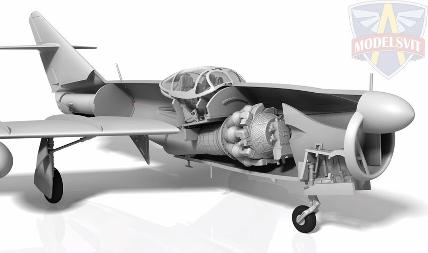
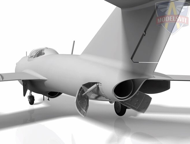
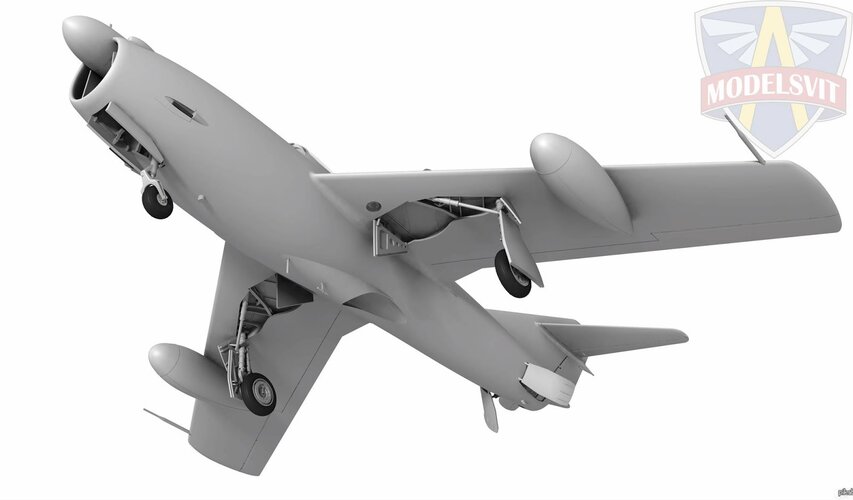
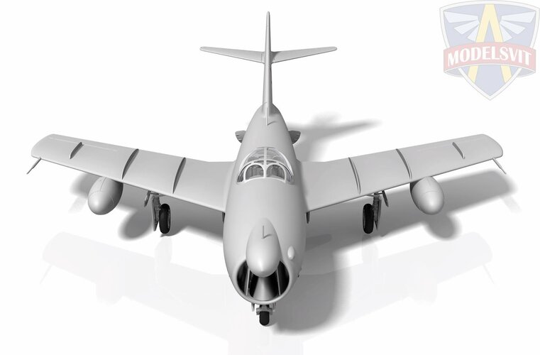
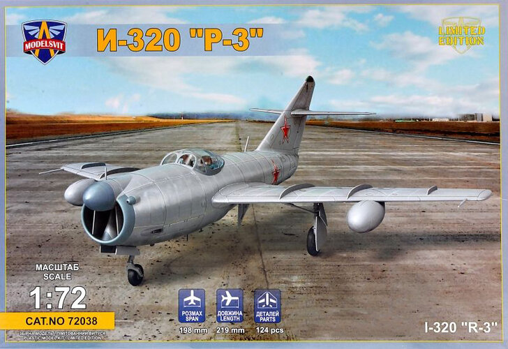
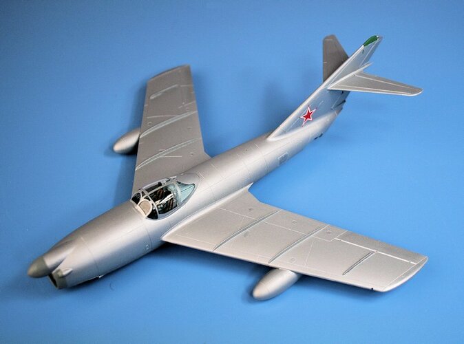
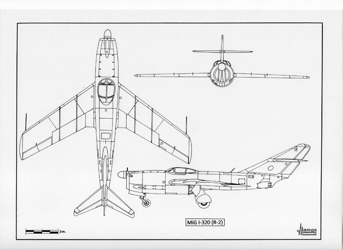
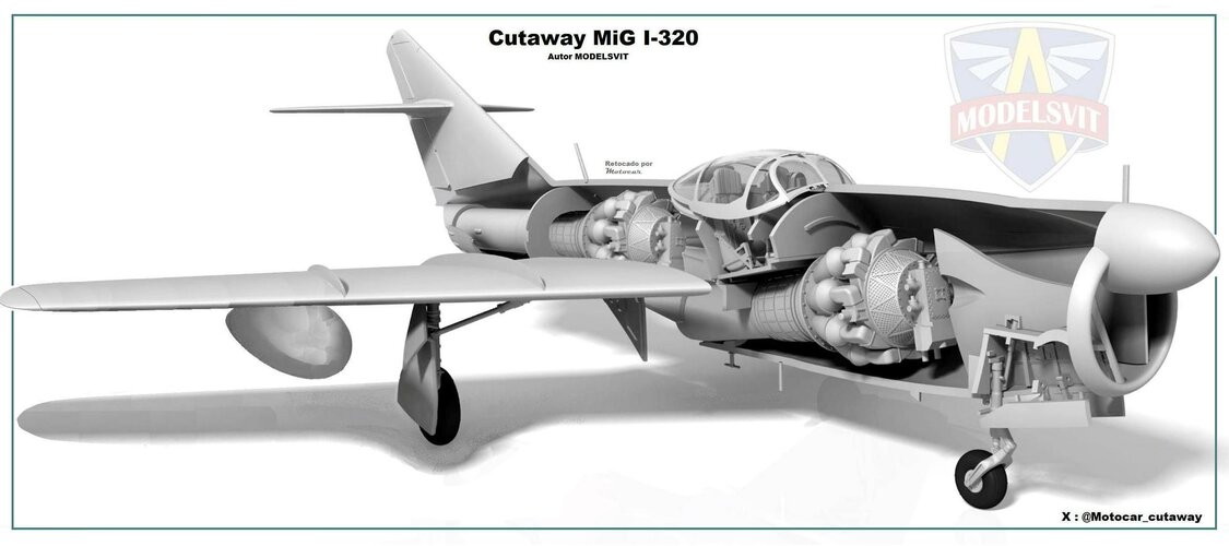
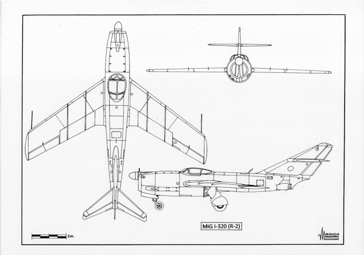
The MiG OKB decided to build the I-320 heavy fighter (a 50 per cent scaled up version of the MiG-15) powered by two RD-45F turbojets mounted inside the fuselage in stepped configuration. The forward engine exhausting beneath the fuselage belly and the aft engine exhausting at the tail.
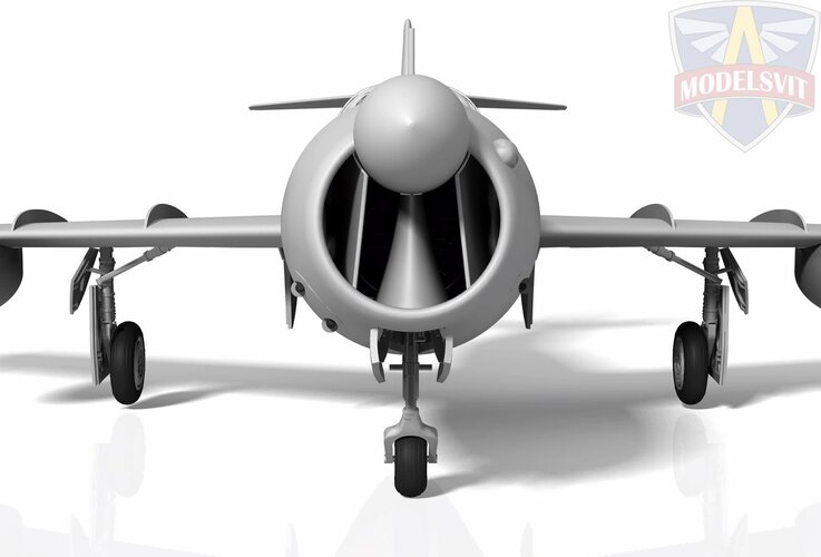
Both turbojets aspirated through the same nose air intake.
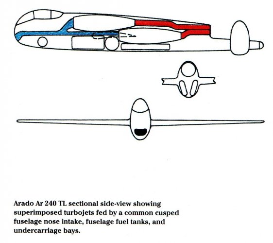
This unusual configuration that generated less drag, had already been studied in 1942 by the German designers of the Arado Ar 240 TL heavy fighter project.
And it had also been studied independently by the Japanese designers of the Yokosuka R2Y2
Keiun jet bomber in 1945.
It was expected that the I-320 could operate as high-performance interceptor when the two afterburners were engaged and that could also operate as escort fighter using a single engine to save fuel.
On December 7, 1948, the Council of Ministers issued a decree calling for the development of a new generation of AI radars able to operate on centimetric wavelengths using the German technology of the Telefunken radars FuG 222
Pauke S, FuG 240/3
Berlin N3 and FuG 244
Bremen 0.
The centimetric wavelengths conversion started with the AI radar Slepushkin
Toriy which provided search, track and gun-ranging using a single parabolic antenna with 60 cm of diameter.
But
Toriy proved to have unreliable and too difficult to use, its manually operated antenna based on that of the FuG 244, has scanning angles of only +30 and -30 degrees and could not operate at the 8g design limit of the I-320.
The radar was designed with a range of 15 km, but during flight tests with the I-320 prototype, it only managed to detect a Tupolev Tu-4 bomber (the Soviet version of the B-29) 7 km away.
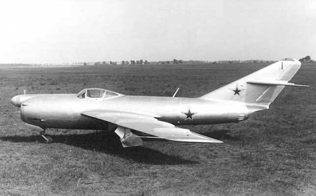
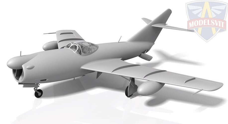
The I-320 looked like a MiG-15 with a second turbojet mounted in
redan configuration, one radar radome fitted at the top of the nose and a Mosquito-style, two-seat unpressurized cockpit.
The R-1 prototype flew on April 16, 1949, but during the State acceptance trials the plane experienced the same tendency as the MiG-15 to drop a wing at high-speeds.
The appearance of the aerodynamic phenomenon
valyozhka (spontaneous rolling) at Mach 0.895 made it necessary to limit its maximum speed, to avoid structural damage.
The R-2 prototype was flown in December 1949 reaching 1,047 km/h top speed and 15,000 m ceiling powered by two VK-1 turbojets rated at 2,700 kg thrust each.
In July 1951 its unreliable
Toriy-A was replaced by one
Korshun AI radar set, based on the FuG 240/3, which offered better performance although still not adequate.
Both types using manually operated scanners, but the
Korshun's parabolic antenna is only 45 cm in diameter and could operate at greater scanning angles.
The VK-1 turbojets proved to be too thirsty and caused the I-320 to only be able to reach the necessary range using two underwing drop tanks.
The I-320 was cancelled in the spring of 1951 in favor of the Yak-25
Flashlight fitted with one
Sokol (FuG 222) radar with 1 m of diameter parabolic mirror and powered by two wing-mounted, axial-flow turbojets.
MiG-I-320 R-2 technical data
Wingspan: 46.6 ft. (14.22 m), length: 51.7 ft. (15.77 m), height: 16 ft. (4.88 m), wing surface: 458 sq. ft. (41.2 sq. m), take-off weight: 26,190 lb. (11,864 m), maximum speed: 660 mph (1,047 km/h), ceiling: 49,200 ft. (15,000 m), range: 2,075 km with two underwings drop tanks, equipment: RV-2 radio-altimeter,
Barii IFF transponder and RSIU-6 R/T.