- Joined
- 26 May 2006
- Messages
- 34,911
- Reaction score
- 15,789
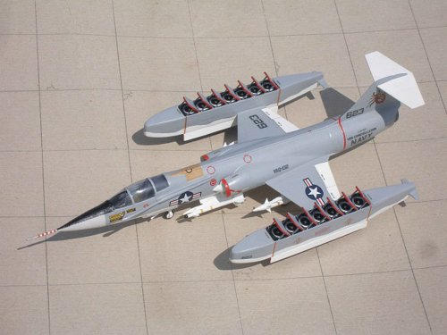
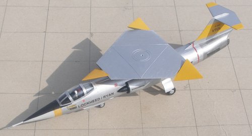
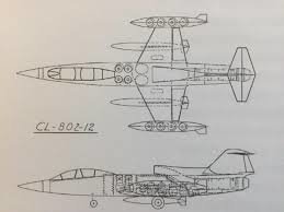
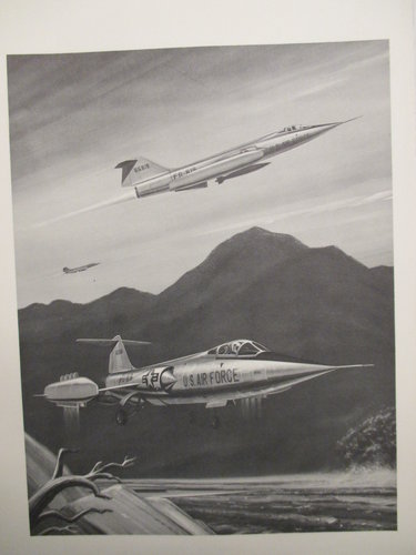
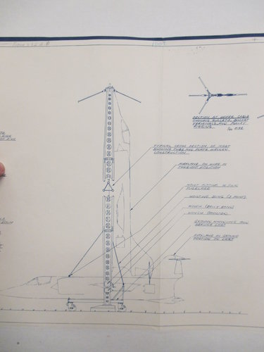
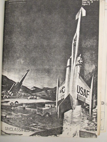
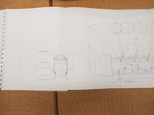
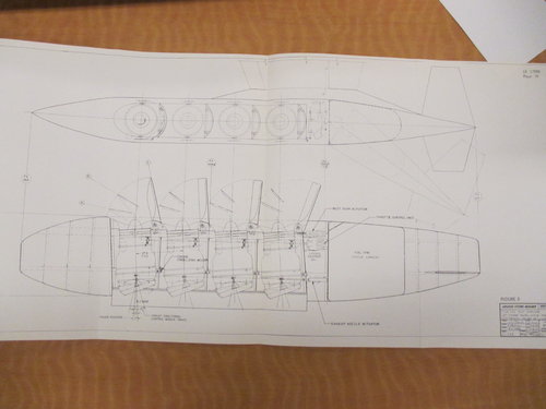
RAP said:Drawings of the VSTOL F-104, Model CL-521.
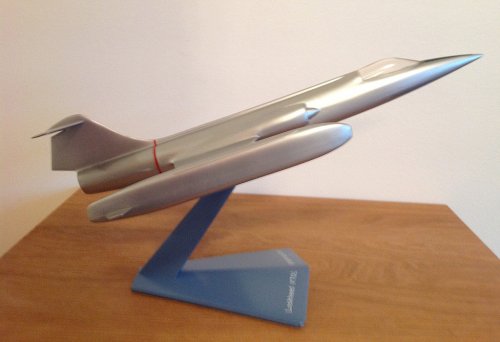
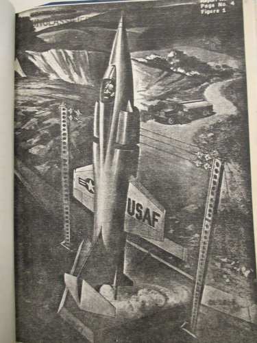
And anther artist drawing to CL-521.
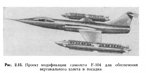
Самолеты вертикального взлета и посадки (1966)

RAP said:Drawings of the VSTOL F-104, Model CL-521.

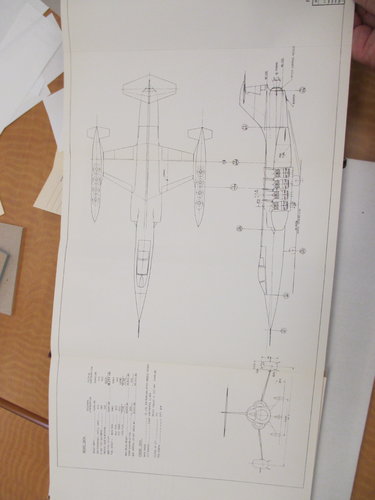
The best F-104 VTOL variant in my opinion.Hi!
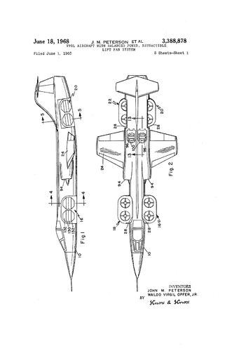
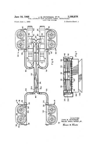
"In the drawing from the patent description, the inlets marked with 96 are sealed by the 100 lids. These are the extra air sources for the engines of the stationary machine. The bottom diagram showing the engine system shows that two gas turbines, apparently smaller than the J79(maybe J85?) were counted this time."
Did anyone build a wind tunnel model or ground spin rig of the triangular rotor?Photograph (first image) of Pete Girard holding a model of a jet-powered heliplane concept. Girard was project engineer of special projects at Ryan Aeronautical Co. in San Diego, CA.
Photograph (second image) of a model of Girard's jet-powered heliplane concept.
Source: "Supersonic Helicopter" Popular Mechanics August 1962 p. 69.