
You are using an out of date browser. It may not display this or other websites correctly.
You should upgrade or use an alternative browser.
You should upgrade or use an alternative browser.
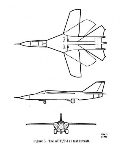
HIMAT and the other AFTI Projects
- Thread starter Andreas Parsch
- Start date
- Joined
- 26 May 2006
- Messages
- 34,896
- Reaction score
- 15,759
- Joined
- 26 May 2006
- Messages
- 34,896
- Reaction score
- 15,759
Stargazer2006 said:Cool find. Always loved the HiMAT.
Thank you Stargazer,we always love HiMAT;
http://ntrs.nasa.gov/archive/nasa/casi.ntrs.nasa.gov/19810009523_1981009523.pdf
Attachments
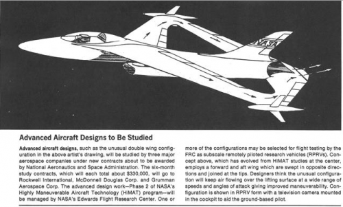
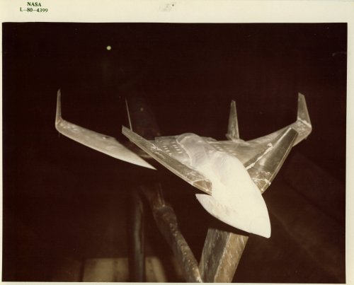
Andreas Parsch said:Unfortunately, the source has a rather bad reliability record (regarding other "info" I received), and I'd like to know if anyone else can say something about this design.
From Darold Cummings via Aerofranz...
Attachments
- Joined
- 27 December 2005
- Messages
- 17,748
- Reaction score
- 26,409
Related to this, earlier in topic, which differs mainly in intake position.

- Joined
- 4 May 2008
- Messages
- 2,439
- Reaction score
- 762
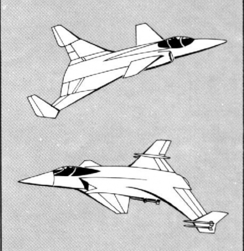
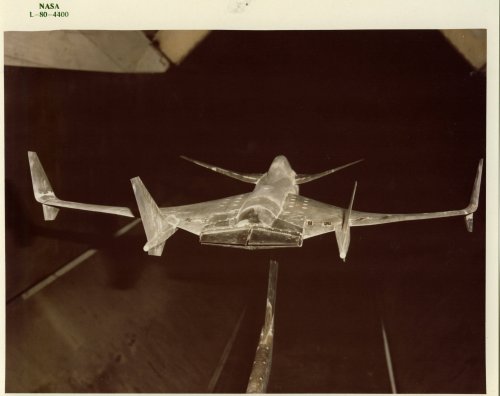
I asked Darold Cummings about the genesis of the obviously related vehicle with side inlets:
"My job on the three-surface aircraft was to make the one you have pictured actually work. No one believed the canard would work in front of the inlet (other than straight and level flight), so my boss asked me to design an aircraft that looked very similar, but could actually fly! This concept never went forward, as it was replaced with my AFTI two-surface concept. The AFTI was the first project I was chief designer on, because my two-surface design proved to be better all-around than the three-surface design."
"My job on the three-surface aircraft was to make the one you have pictured actually work. No one believed the canard would work in front of the inlet (other than straight and level flight), so my boss asked me to design an aircraft that looked very similar, but could actually fly! This concept never went forward, as it was replaced with my AFTI two-surface concept. The AFTI was the first project I was chief designer on, because my two-surface design proved to be better all-around than the three-surface design."
- Joined
- 3 June 2006
- Messages
- 3,094
- Reaction score
- 3,961
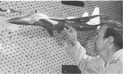
A Rockwell HiMAT is now shown outdoor in front of the Visitor Center of Neil A. Armstrong Flight Research Center (Before March 1, 2014: Dryden Flight Research Center (DFRC)).
Link: View: https://twitter.com/NASAArmstrong/status/440636462011125760/photo/1
Link: View: https://twitter.com/NASAArmstrong/status/440636462011125760/photo/1
Last edited by a moderator:
pathology_doc
ACCESS: Top Secret
- Joined
- 6 June 2008
- Messages
- 1,587
- Reaction score
- 1,507
When I was a kid, I read about HiMAT in some early 1980's speculative-future book in my classroom, pitched at the nine-year-olds we then were, that I now can't remember the name of (which is a pity).
We were promised Mach 5 and a laser cannon.
To quote Lord Voldemort, "I confess myself... disappointed."
We were promised Mach 5 and a laser cannon.
To quote Lord Voldemort, "I confess myself... disappointed."
- Joined
- 26 May 2006
- Messages
- 34,896
- Reaction score
- 15,759
- Joined
- 26 May 2006
- Messages
- 34,896
- Reaction score
- 15,759
Yes my dear AeroFranz,
and in the same article,I found anther three drawings to MD,Grumman and GD,but I suspect in Grumman and GD proposals,may be the Author was wrong.
and in the same article,I found anther three drawings to MD,Grumman and GD,but I suspect in Grumman and GD proposals,may be the Author was wrong.
Attachments


Last edited:
- Joined
- 2 August 2006
- Messages
- 3,255
- Reaction score
- 1,527
hesham said:Yes my dear AeroFranz,
and in the same article,I found anther three drawings to MD,Grumman and GD,but I suspect
in Grumman and GD proposals,may be the Author was wrong.
The manufacturers are right, it's the program that's wrong. Those aren't AFTI submissions. Those are STOVL aircraft. I don't remember which acronym they belong to, though..
- Joined
- 2 August 2006
- Messages
- 3,255
- Reaction score
- 1,527
hesham said:Hi,
is this ATFI project relate to Fairchild-Republic or MD ?.
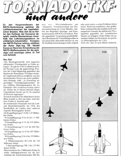
Flieger Revue 11/1980
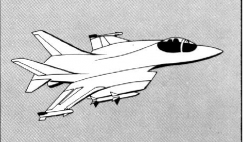
The one on the right is MD and is also shown in the Secret Projects logo at the top of this web site.
- Joined
- 27 December 2005
- Messages
- 17,748
- Reaction score
- 26,409
hesham said:Yes my dear AeroFranz,
and in the same article,I found anther three drawings to MD,Grumman and GD,but I suspect
in Grumman and GD proposals,may be the Author was wrong.
McDonnell-Douglas 263 (VFAX)
Grumman 623 (conventional - VFAX, STOVL - VFA)
Convair 200/201/218 (conventional - VFAX, STOVL - VFA)
- Joined
- 27 December 2005
- Messages
- 17,748
- Reaction score
- 26,409
hesham said:Hi Pathology_doc,
but 5 Mach fighter is useless and laser gun can't precisly define the targets.
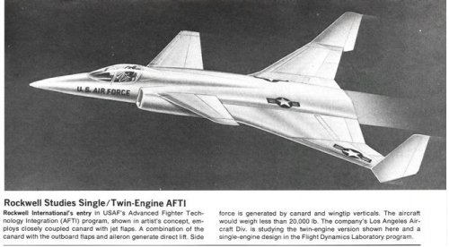
Here is also a Rockwell AFTI concepts,from Flieger Revue 11/1980
The first is an early (1973) Rockwell AFTI concept, the second is XFV-12.
- Joined
- 27 December 2005
- Messages
- 17,748
- Reaction score
- 26,409
Flieger Revue was an East German magazine, so in 1980 would have been reliant on the Western press for information on Western programs.
Avimimus
ACCESS: Top Secret
- Joined
- 15 December 2007
- Messages
- 2,426
- Reaction score
- 907
pathology_doc said:When I was a kid, I read about HiMAT in some early 1980's speculative-future book in my classroom, pitched at the nine-year-olds we then were, that I now can't remember the name of (which is a pity).
We were promised Mach 5 and a laser cannon.
I remember this - it existed (the book). I think it might also have had a watch-gps.
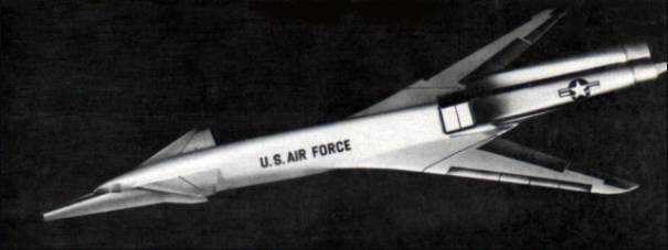
Boeing concept found on eBay. Anyone recognize this concept? Late 1970's fighter interceptor concept?
Source:
http://www.ebay.com/itm/RARE-Vintage-Boeing-Factory-Concept-Art-Print-Super-Sonic-Aircraft-/221512955897?pt=LH_DefaultDomain_0&hash=item33933377f9
Source:
http://www.ebay.com/itm/RARE-Vintage-Boeing-Factory-Concept-Art-Print-Super-Sonic-Aircraft-/221512955897?pt=LH_DefaultDomain_0&hash=item33933377f9
Attachments
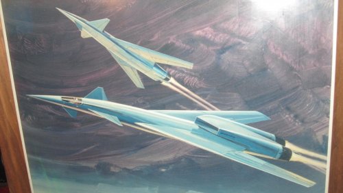


Triton said:Boeing concept found on eBay. Anyone recognize this concept?
It's a Control Configured Vehicle concept from the latter 1970's. I have high hopes of snagging this one (but, sadly, low expectations). I've seen virtually the same configuration, but scaled up to bomber size, in both sketches and a patent. First time I've seen it fighter size, though.
Edit: This'n:
From: http://www.hitechweb.genezis.eu/bombers1c.htm
Cool, I found something new.
- Joined
- 27 December 2005
- Messages
- 17,748
- Reaction score
- 26,409
Rockwell’s HiMAT RPRV-870 (part 1)
The Rockwell International RPRV-8870 HiMAT.
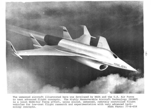
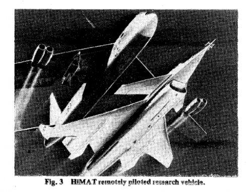
Rockwell International’s RPRV-870 (Remote Piloted Research Vehicle) HiMAT (Highly Maneuverable Aircraft Technology) was a joint USAF/NASA program to develop advanced technology for future fighter aircraft. There were 2 aircraft flown for a total of 26 flights. The 0.44 scale RPVs tested advanced technology concepts like composite and metallic structures, digital integrated propulsion control, and ground and airborne relaxed stability digital fly-by-wire.
Many of the aircraft technologies that we use today came from HiMAT developments of the 1970s and 80s. HiMAT’s main advantage was that it was able to test several of these technologies in a synergistic manner, integrating as many of these technologies as possible. The program was operated and funded jointly by the USAF and NASA.
In August 1975, Rockwell International was awarded the contract to build 2 subscale unmanned vehicles. These were delivered to NASA’s Dryden Flight Research Center in March and June 1978.
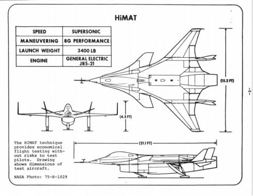
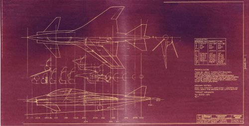
HiMAT technologies and 3-view.
HiMAT technologies and 3-view.
One of the main research goals of the HiMAT program was to provide a mathematical foundation for the use of computational tools in comparative analysis of future aerodynamic and structural design and to provide high quality flight test data for correlation and comparison with flight test data. Goals for the vehicle itself included testing of advanced aerodynamic configurations and advanced design concepts like composites, metallic structures, a digital integrated propulsion system (IPCS) and ground to airborne digital fly-by-wire concepts.
Structurally, the HiMAT, design goals were to provide “compromises when necessary to integrate several new technologies into a system with real constraints that must allow a significant level of benefit of the technology to be realized.” As a result of this integration, designers realized that “late discoveries of these unpredictable problems may significantly impact cost and/or schedule performance.”
In turn, the HiMAT vehicle was driven by several design goals and constraints:
1. Most importantly the design must integrate, to the highest fidelity possible the technologies mentioned above.
2. The configuration had to be representative of a realistic (future) air-to-air fighter.
3. The additional constraints of scaling effects and RPRV requirement.
4. The transonic sustained maneuver requirement of 8g’s coupled with efficient performance.
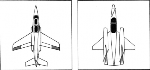
The overall structural approach was design a full-scale fighter that had the desired full technology integration and then develop the RPRV with minimum compromises. Keeping this in mind it was necessary to match thrust-to-weight (T/W) and wing loading (W/S) of a full-scale fighter so that equivalent maneuvering performance could be achieved with the RPRV. Another constraint imposed was the off the shelf availability of the J85-21 engine, so the best match in terms of size and performance was to be the 0.44 scale factor.
HiMAT fighter to RPRV comparison.
HiMAT fighter to RPRV comparison.
The design of HiMAT was also driven by 3 major factors:
1. Aerolastic tailoring to provide the aerodynamic required twist and camber distributions.
2. Maximum use of advanced materials, both metallic and nonmetallic.
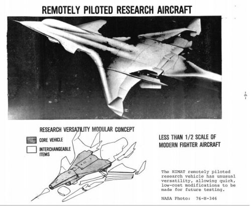
3. Modular design so that components of the airplane could be replaced with alternate designs for research purposes.
HiMAT's modularity
HiMAT’s modularity
HiMAT's modularity
HiMAT’s modularity
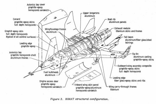
The HiMAT design used several advanced materials and composite structure applications. HiMAT trade studies and fabrication experience dictated that graphite/epoxy be the material for primary and secondary lifting surface structures. Control and lifting surfaces were designed and fabricated to meet the program’s torsional stiffness requirements. This had the added benefit of saving 25 to 40% of what otherwise would have been the vehicle’s weight. Development of HiMAT’s structure included the first utilization of the TSO composite design optimization computer program.*
HiMAT construction by material.
HiMAT construction by material.
A primary feature of the HiMAT, was its construction from advanced materials. The wing and canard were constructed from graphite-epoxy using a non-standard ply technique. This provided an aerodynamically beneficial spanwise aeroelasticity to reduce vehicle drag. The vehicles were also designed to fly in a relaxed stability configuration to further reduce drag. NASA established the goal that the HiMAT vehicle have the ability “to perform a sustained 8-g turn at Mach 0.9, at an altitude of 30,000 feet, with a mission radius of 300 miles.”
The RPRV (Remotely Piloted Research Vehicle), which the HiMAT was, had systems requirements that no single systems failure could result in the loss of the vehicle and the vehicle must fly statically unstable. This meant that the approach to flight control systems, vehicle systems, fault detection and failure management systems, and systems flight qualification all required an unheard of level of complexity. All of HiMAT’s systems could be divided into primary and backup. There were dual onboard microprocessor computers as well as dual electrical and hydraulic systems as well as duel flight control systems and redundant flight sensors.
The overall vehicle configuration was that of a “close coupled canard with a swept wing.” The control surfaces included twin all-movable twin rudders mounted on a boom. The rudders deflected symmetrically for yaw control and asymmetrically for speed brake control. The elevator was used for pitch control, elevons for pitch and roll control. The canard flaps were capable of pitch and sideforce control but were not used as such.
HiMAT gross weight was 3501lbs with 659lbs of fuel. Each vehicle was powered by a J85-21 turbojet engine rated at 5004lb of sea level static thrust. Engine control was provided through an IPCS in the backup computer. Vehicle subsystems were also powered by an engine-driven electrical generator with backup power supplied by a 35V silver-zinc battery. Primary hydraulic power was supplied by an engine-driven pump with a backup electrical pump. There were no single points of contact between the primary and backup hydraulic systems other than the dual tandem actuators for the rudders.
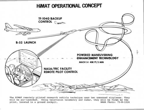
HiMAT's operational concept.
HiMAT’s operational concept.
HiMAT mounted on the pylon of NASA's B-52 mothership.
HiMAT mounted on the pylon of NASA’s B-52 mothership.
Flight tests were conducted with the HiMAT dropped from at B-52 mothership at about 45,000ft at Mach 0.68. The vehicle was placed on the right wing of the B-52 on a specially modified pylon. Typical missions lasted about 30 minutes. The pilot (or rather operator) sat in a fully instrumented, fixed base ground cockpit. The pilot would fly HiMAT with typical fighter-type controls, a center stick and left side throttle.
HiMAT cockpit.
HiMAT cockpit.
Control of HiMAT was maintained through ground control and uplink computers and aircraft response was downlinked to a ground station and indicated to the pilot via conventional aircraft instrumentation. A flight engineer sat next to the pilot and assisted the pilot with the conduct of maneuvers and navigation. NASA ground radar provided tracking, backup airspeed and altitude information. In the event of systems failure, the backup systems could be engaged by the chase aircraft (a NASA TF-104) or at the ground station.
HiMAT was equipped with skids for landing on the Rogers Dry Lakebed. Typical landing runs were 4500ft along the 15000ft runway.
Simplified diagram of HiMAT's different signal paths.
Under typical flight conditions HiMAT was flown via the Primary Control System (PCS). The PCS control laws ran from a ground-based Varian V-73 computer. In the event, the PCS failed, there was a Back-Up Control System (BCS) whose program was run either based on a failure of the PCS or could be engaged manually from the chase aircraft or the ground station. The BCS control laws were resident in the backup computer aboard the vehicle.
The downlink receiving station processed data from the primary on board computer to the flight test instrumentation system (FTIS) for transmission in a modulated data stream at 220HZ. The ground station then processed this data into usable words using a Varian V-77 computer.
Cockpit displays on the pilot’s fixed station included a forward-looking video monitor, attitude direction indicator (ADI), a radar altimeter, barometic altimeter, airspeed and Mach indicators, altitude rate, engine rpm, fuel flow, fuel quantity, and exhaust gas temperature (EGT), a computer select mode control (CSMC) box and pulse panel. As previously mentioned, the pilot’s interface to the PCS was through the standard fighter aircraft 3-axis controls made up of a stick, throttle lever, and rudder pedals. A speed brake switch was provided on top of the throttle lever. Interface to the BCS was via command switches located to the left and right of the main console, also in the pilot’s cockpit.
No vehicle data was provided to the chase TF-104 so the aircraft provided control and guidance visually.
The flight test engineer (FTE) communicated with the pilot for assistance with navigation, checklist and emergency procedures, pulse panel tests, system gain changes and landing emergency management. Navigation was done via a radar driven plot board showing the position in a track above the ground. Energy management during landing was also display on a radar driven slope plot board. Pulse panel inputs were initiated by the FTE and consisted of pre-programmed commands given to the pilot.
Three computers were used to perform the PCS control law, maneuver autopilot and navigational computation functions. These were the Varian V-73A, V-73B and V-72 computers, respectively. The vehicle downlinked sensor signals and were processed through the V-77 then combined with control inputs from the pilot via the V-73A computer (using the PCS control law commands). The V-73 also performed air-data calculations for display in the ground cockpit. Additional functions carried out by the V-73 was the automated prefilght program that tested all interface input/output.
The V-73 also had a mechanized flight test maneuver autopilot (FTMAP). The FTMAP “was designed to provide precise, repeatable control of HiMAT during certain prescribed maneuvers.” FTMAP acted as a “non-flight-critical” outer loop controller with the PCS. During FTMAP operation, the FTMAP computer replaced all pilot imputs. The FTMAP also passed landing guidance information to the cockpit’s ADI.
The V-72 received and decoded tracking radar data and calculated vehicle ground track information for display to the pilot. The V-72 also provided a limited ILS (Instrument Landing System) i.e. glideslope and localizer information for display in the cockpit.
The uplink encoder, combined signals from the pilot’s input and output from the V-73 computer before sending the commands to the vehicle. The encoder formatted to send data in four 16-bit words per frame at a rate of 106.6 frames per second. Two different frames were alternately sent for a total of 8 16-bit updated 53.3 times/second. The data itself was formatted as:
The first four words addressed vehicle decoder number one, and the last four words addressed vehicle decoder number two. The first 10 bits of each words were available only to the primary onboard computer and were designated proportional data. These proportional channels represented the PCS interface to the vehicle aerodynamic surfaces and throttle. The last 6 bits of each word were designated as manual command discretes and were hardwired directly to the encoder from cockpit switches. These discretes represented the pilot’s discrete interface to the onboard BCS and other vehicle systems.
In terms on airborne systems, the PCS required that both receivers and decoders be operational. Dual receivers-decoders received the uplink signal and provided the command input interface to dual onboard computers. Early in the program the vehicle experienced frequent automatic transfers from PCS to BCS because the either one of both of the receivers-decoders received inadequate uplink signals as a function of vehicle attitude. To alleviate this these nuisance transfers to the BCS, a diversity-combining concept was used in the hardware to prevent an interruption of the groundlink signal. The diversity combiner combined output signals of the dual receivers so regardless of vehicle orientation, the best continuous signal was available for uplink commands. As the diversity combining hardware was installed in vehicle number one, it eliminated nuisance transfers to the BCS.
Dual onboard custom built computers provided critical systems control for the HiMAT. These 2 computers were based on Intel 8080 microprocessors. and operated asynchronously but had identical computational and memory capacities:
Each computer contained 22,528 bytes (8 buts) of erasable, programmable, read only memory (ROM) and 1024 bytes of random access memory (RAM). Both computers were programmed entirely in 8080 assembly language and packaged in a common chassis with separate circuit cards and connectors. The dual computer chassis weighed 40lb and had a volume of 1198in3
The principal functions of the primary computer were:
1. uplink data processing.
2. downlink data processing.
3. failure detection for the computers, flight sensors, servoactuators, and power system (for both the PCS and BCS).
4. failure detection for the IPCS
The functions for the backup computer were:
1. uplink data processing.
2. primary IPCS.
3. BCS control laws.
The computers communicated with other vehicle systems via digital, analog and discrete channels. Each computer also had its uplink and downlink telemetry systems.
HiMAT had 7 redundant flight critical system sensor sets that provided the vehicle with a “fail-safe” capability. 5 of the sensor sets were triplex and the 2 other were duplex. The 7 sensor sets:
included the triplex three axis angular rate gyros, normal and lateral accelerometers, and the duplex air data system.
Air data rates were determined by an analog differentiation of the air data signals. A single sensor of each set was designated the backup to the BCS. A simplex all-attitude gyro and radar altimeter were provided but not deemed “flight critical.” The gyro provided data to the vehicle’s ADI and to a “direction cosine algorithm” in the BCS code. The radar altimeter provided data to the pilot at all altitudes below 5000ft during approach and provided critical input to the BCS in automatic landing mode. The BCS could even be used to land the vehicle even if the radar altimeter failed.
The servoactuator electronics (SAE) box provided an interface between the onboard computers and the control surface actuators as well as the engine nozzle. The SAE box functions included:
electrically closing all servo loops to the actuators, receiving all actuator command from the computers and feeding back all actuator positions to the computers.
Another primary function was failure detection of the elevon servoactuator system which was sensed faster in hardware than software. If a failure was detected the SAE would notify the primary computer.
Rounding out the airborne systems of the 2 HiMAT vehicles, is a flight test instrumentation system (FTIS). The FTIS processed all data to be downlinked into a PCM data stream. Inputs to the FTIS were both analog and digital. Some signals were downlinked directly through the FTIS and through the onboard computer. Some downlinked data was processed through the downlink processing routine in the FTIS. The downlink processing routine included midvalue selection of triplex sensors, synchronization logic and the packing of vehicle status and failure indication discretes. The routine formatted and processed data eighteen 10-bit proportional parameters and seven 10-but discrete words.
In part 2 we’ll discuss the HiMAT flight test program and results.
Another view of HiMAT at landing.
Another view of HiMAT at landing.
*The TSO (aerolastic tailoring and structural design optimization) computer program provides aerolastic tailoring information for lifting surfaces.
http://thelexicans.wordpress.com/2014/01/19/rockwells-himat-rrpv-part-1/
Drat. Too rich for my blood.
Orionblamblam said:Drat. Too rich for my blood.
Sold for $57.66.
- Joined
- 31 May 2009
- Messages
- 1,154
- Reaction score
- 674
Triton said:Orionblamblam said:Drat. Too rich for my blood.
Sold for $57.66.
Clearly, we need to buy more APRs...
- Joined
- 26 May 2006
- Messages
- 34,896
- Reaction score
- 15,759
Attachments
- Joined
- 26 May 2006
- Messages
- 34,896
- Reaction score
- 15,759
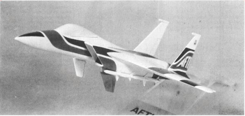
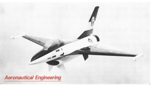
PaulMM (Overscan) said:Here are two AFTI projects for modified F-15 and F-16
Source:
- Klaus Huenecke, Modern Combat Aircraft Design Airlife 1984 (based on article cited above)
And from Aviation Week;
http://archive.aviationweek.com/image/spread/19780911/55/2
http://archive.aviationweek.com/image/spread/19780109/32/2
Attachments
- Joined
- 26 May 2006
- Messages
- 34,896
- Reaction score
- 15,759
jsport
what do you know about surfing Major? you're from-
- Joined
- 27 July 2011
- Messages
- 7,732
- Reaction score
- 5,751
Wow, missed this amazing. Thank you yet again Hesham.hesham said:PaulMM (Overscan) said:Here are two AFTI projects for modified F-15 and F-16
Source:
- Klaus Huenecke, Modern Combat Aircraft Design Airlife 1984 (based on article cited above)
And from Aviation Week;
http://archive.aviationweek.com/image/spread/19780911/55/2
http://archive.aviationweek.com/image/spread/19780109/32/2
- Joined
- 27 December 2005
- Messages
- 17,748
- Reaction score
- 26,409
PaulMM (Overscan) said:Related to this, earlier in topic, which differs mainly in intake position.
Related Rockwell jet flaps demonstrator report:
Last edited:
- Joined
- 29 January 2008
- Messages
- 916
- Reaction score
- 2,054
- Joined
- 27 December 2005
- Messages
- 17,748
- Reaction score
- 26,409
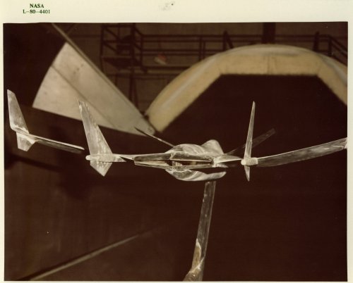
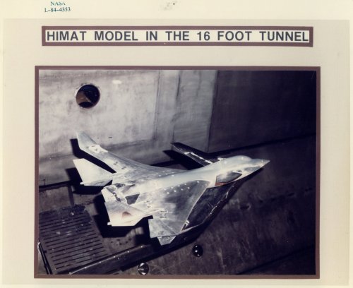
https://crgis.ndc.nasa.gov/historic/Test_346:_HiMAT_Single_Ramp_Nozzle
Test 346 was conducted on a 0.147-scale propulsion model of the HiMAT (Highly Maneuverable Aircraft Technology) RPRV (Remotely Piloted Research Vehicle) during 5/7/1980 to 6/6/1980. This model was tested previously during Tests 308 and 328 (2-D wedge nozzles).
Attachments
Similar threads
-
Nemeth Umbrellaplane ("Roundwing") and other projects
- Started by Nico
- Replies: 15
-
 The life and times of the Vought V-70 demonstrator
- Started by Stargazer
- Replies: 2
-
-
MiG 17 Projects, Prototypes and Experimental Variants
- Started by Justo Miranda
- Replies: 3
-
 "Cold War American Spacecraft Projects and the “Paperclip” connection."
- Started by Orionblamblam
- Replies: 9