- Joined
- 27 December 2005
- Messages
- 17,751
- Reaction score
- 26,427

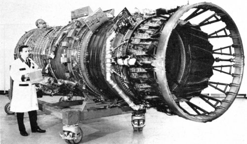
GE4/J5P
Type: Single-shaft axial turbojet with afterburner.
Intake: Annular, comprising front structural frame with eight radial struts supporting compressor front bearing housing.
Compressor: Nine-stage axial single-shaft unit with variable incidence inlet guide vanes and stator vanes, giving large stall margin for inlet distortion tolerance. Front and rear groups of stators are individually actuated for starting airflow control and for high airflow capability at supersonic speeds. Rotor construction is combined drum-and-disc with thin-section centreless discs. No 1 disc is overhung on forward conical extension shaft supported by compressor front roller bearing. Rearward conical extension shaft attached to periphery of No 9 disc is supported by centre main ball thrust bearing. Thin-section air tube located on front and rear conical shafts, passes through disc centres. Compressor delivery diffuser is integral with mid-section structural frame supporting centre main bearing. All stator vanes carried on inner and outer swivel bearings, with inner support rings sealing against rotor inter-disc drums. For reduced weight, rotor blades in stages 1 to 4 are hollow diffusion-bonded titanium alloy, and stage 5 to 9 electro-chemically drilled superalloy. Pressure ratio 12-5:1, mass flow 633 lb/sec (287 kg/sec).
Combustor: Fully annular design of moderately high heat release rate with primary air annulus having multiple axial swirl cups.
Turbine: Two-stage axial unit with air-cooled cast alloy nozzle guide vanes and rotor blades. Thin-section centreless discs with arched inter-stage spacers. Rotor blades have dovetail root fittings and second stage blades are tip-shrouded. Forward conical extension shaft attached to periphery of stage 1 disc locates with compressor rear conical shaft at centre main ball thrust bearing. Rearward tubular shaft extension from stage 2 disc located in rear main roller bearing. Stage 2 nozzle guide vanes cantilever mounted from outer end, with seal onto interdisc spacer at inner end.
Exhaust System: Annular exhaust duct from turbine with rear structural frame, with radial/tangential struts, supporting curved centre cone and turbine rear bearing. Turbine entry temperature at T-O, in excess of 2,000°F (1,366°K).
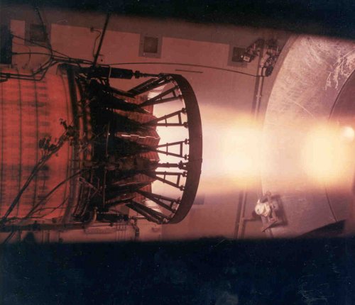
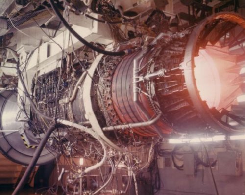
Afterburner: Conventional system with four V-gutter flame stabilisers mounted on radial struts in exhaust duct. Two-stage fuel injection enables thrust modulation over full augmentor temperature range. Annular thermal shield protects duct wall between combustion zone and variable nozzle. Fuel supply manifold encased in external annulus around exhaust duct.
Exhaust Nozzle and Thrust Reverser: Two-stage nozzle with integral thrust reverser. Comprises variable area primary nozzle positioned by hydraulic actuators which also "overtravel" to act as reverser blocker. Long-section secondary shroud includes tertiary air inlet doors which open for low speed operation and can be selectively locked open for reverser operation. Secondary nozzle provides guided expansion of exhaust gases and is pressure-positioned for optimum area ratio. For reverse thrust, primary nozzle translates rearwards to expose thrust reverser ducts (tertiary air inlet doors), closing to form a block, thus directing gases forward through the ducts. Provision also for noise suppression.
Fuel Systems: Hydromechanical primary engine and afterburner fuel control systems.
Accessories: All engine controls and accessories housed in sealed compartment under front of engine cooled by normal circulation of fuel to protect from high temperature environment at supersonic cruise. Accessory drive is via bevel gear box in nose cone, driven-ofF front of compressor. Drive shafts for accessories and airframe purposes pass through front frame radial struts.
Dimensions:
Max diameter (over exhaust nozzle) 89.5 in (2,280 mm)
Length overall 308 in (7,823 mm)
Weight, dry: (Dependent on specific installational features) 11,300 lb (5,100 kg)
Performance Ratings: Max augmented T-O
67,000 lb (30, 390kg) st at 5,200 rpm Max augmented T-O
50,500 lb (22,900 kg) st at 5,200 rpm Max flight conditions
Mach 2.7 at 82,000 ft (24,994 m)
Cruise at Mach 2.7 and 65,000 ft (19,812 m) 15,000 lb (6,804 kg)
Specific Fuel Consumption:
At cruise rating 1.50 lb/lb/hr (1.50 kg/kg/hr)
")
Overkiller said:While on the subject of SST powerplants, does anyone have any info whatsoever on P&W's loser to the GE4?
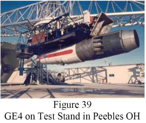
elmayerle said:This engine saw lots of ground testing but was never, to the best of my knowledge, flight tested. I'm really not certain how they could have flight tested it in the supersonic region, anyway. The flight tests of the J93 utilized a pod that just barely fit under the B-58 carrying it and the GE4 was a larger engine.
Overkiller said:While on the subject of SST powerplants, does anyone have any info whatsoever on P&W's loser to the GE4?
elmayerle said:Pratt & Whitney's engine was the JFT20, an afterburning two-spool turbofan that shared technology with the JFT22 (F100/F401) that developed from the experimental JTF16 engine. When the SST mockup was in a museum in Kissimee, Florida, they had a JTF20 engine there on loan from P&W.
Overkiller said:I seem to recall that at one stage the XB70 was proposed as a possible supersonic tesbed for this engine.
I think there is reference to this in the excellent Tony Landis book on the XB70, I think the idea was to replace several of the YJ93's on one side with a single GE4?
One thing I do find extraordinary about this engine is that it appears to have disappeared without a trace, I find it hard to believe that such a powerful engine simply found no application whatsoever!
A few years ago there were some allegations on the FAS website regarding the alleged "Brilliant Buzzard" project where it was speculated that the powerplant could well have been the GE4.
While on the subject of SST powerplants, does anyone have any info whatsoever on P&W's loser to the GE4?
AeroFranz said:I believe the National Air and Space museum had one in their storage facility at Garber. Maybe we'll see it one day when they move everything to the new hangar at Udvar-Hazy.
Sundog said:This is a re-post from within a seperate SST thread we have on U.S. SST's. I'm not sure if you want a seperate thread for the PW engine, since you also have this thread listed as Boeing 2707 SST.
Where is the GE4 located now? Udvar-Hazy?I can confirm that this engine still exists. It was not scrapped out. It is a massive engine.
Where is the GE4 located now? Udvar-Hazy?I can confirm that this engine still exists. It was not scrapped out. It is a massive engine.
Do you know if it can be viewed by the public or by request?At least one is at GE Aviation facilities.
Where is the GE4 located now? Udvar-Hazy?I can confirm that this engine still exists. It was not scrapped out. It is a massive engine.
I can confirm that this engine still exists. It was not scrapped out. It is a massive engine.
The XB-70's J93 already was a monster, but the GE4... was a much scaled-up variant.Turbojet with afterburner:
GE4 Block 1: Hinged primary nozzle and cascade thrust reverser,
GE4/J5 Block 2: Hinged primary nozzle and cascade TR,
GE4/J5P Prototype: Leaf-type primary nozzle and blocker door TR.
GE4/J6G Production Design: Leaf-type primary nozzle and blocker door TR.
The thrust reverser of the latter 2 used the variable segments of the primary nozzle as reverser blockers.
The above variants had lost favor due to noise considerations shortly before B2707-300 project cancellation. There were 2 more development proposals:
Turbojet without afterburner:
GE4/J6H Tentative Design: Favored by program directors, greater simplicity and the need for less new design and development work.
Turbofan with limited afterburner for acceleration to cruise speed:
GE4/J7A Tentative design: "Leaky fan" with a bypass ratio of 0.3.
GE4/J6G: 70,000 lb. (turbojet with AB)
GE4/J6H: 75,000 lb.* (dry turbojet)
GE4/J7A: 75,000 lb.* (turbofan)
* The 2 tentative designs need some further explanation:
Both tentative designs were intended to produce the same maximum 108 perceived noise in decibles (epndb.) in takeoff sideline noise as called for in FAR 36 for new subsonic jet aircraft of that era.
A suppressor would be used with both engines, and improvements in these as well as low-speed lift improvements to the aircraft design helped to reach the 108 epndb. level.
To produce the noise reduction from the 124 epndb. level anticipated in the earlier prototype/production designs, both engines would be used on takeoff at less than full thrust. Thus, according to preliminary projections at the time, each engine would take off using about 55,000 lb. of thrust of the 75,000 lb. available for a 298 passenger aircraft.
Key to the quieter engine performance was the much greater airflow expected from both of the 2 new engines. Tentative engine data indicated a maximum takeoff airflow of 815 lb./sec. This was greater than optimum in order to reduce noise. The turbojet/afterburning prototype engine GE4/J5P, by contrast had a takeoff airflow of 633 lb./sec.
Accompanying the increased airflow, as part of the noise reduction measures, was a decrease in exhaust velocity from 3,500 ft./sec. in the prototype with full afterburner on takeoff to a range of 2,000-2,500 ft./sec. for the tentative new designs. For both the proposed fan and dry turbojet engines, the first stage compressor inlet diameter would be increased from 60.6 to 68.7 in.
Among the additional complications produced by going to a fan engine would be substitution of a 2-spool design for a single-spool planned for the dry turbojet. Both would rely as much as possible on then existing GE4 technology with changes in the combustor and turbine sections primarily only in dimensions.
Part of the takeoff noise reduction would come from a lower power setting (55,000 lb. per engine instead of the previously planned 63,000 lb.). Part of this reduction was possible through better takeoff and climb lift characteristics from the wing than anticipated, but another factor was that the hot-day FAR balanced field length requirement at maximum takeoff weight was to be extended from 10,200 to 12,400 ft.
I haven’t seen those NASA reports posted in the Propulsion forum before. Great reading on the work being done in the early to mid 70sApologies if already posted elsewhere but some interesting GE4 details here:

NASA Technical Reports Server (NTRS) 19770011052: Proceedings of the SCAR Conference, Part 1 : NASA Technical Reports Server (NTRS) : Free Download, Borrow, and Streaming : Internet Archive
The Supersonic Cruise Aircraft Research (SCAR) team analyzed six major topics: (1) aerodynamics, (2) stability and control, (3) propulsion, (4) environmental...archive.org
Thanks for posting!Apologies if already posted elsewhere but some interesting GE4 details here:
NASA Technical Reports Server (NTRS) 19770011052: Proceedings of the SCAR Conference, Part 1 : NASA Technical Reports Server (NTRS) : Free Download, Borrow, and Streaming : Internet Archive
The Supersonic Cruise Aircraft Research (SCAR) team analyzed six major topics: (1) aerodynamics, (2) stability and control, (3) propulsion, (4) environmental...archive.org
My pleasure. Sounds intriguing!Thanks for posting!Apologies if already posted elsewhere but some interesting GE4 details here:
NASA Technical Reports Server (NTRS) 19770011052: Proceedings of the SCAR Conference, Part 1 : NASA Technical Reports Server (NTRS) : Free Download, Borrow, and Streaming : Internet Archive
The Supersonic Cruise Aircraft Research (SCAR) team analyzed six major topics: (1) aerodynamics, (2) stability and control, (3) propulsion, (4) environmental...archive.org
BTW I am slowly restoring a copy of the J93/GE3 assembly repair manual, father of the GE 4.
Source:B-52 projected testbed for GE4