
You are using an out of date browser. It may not display this or other websites correctly.
You should upgrade or use an alternative browser.
You should upgrade or use an alternative browser.
Fisher XP-75
- Thread starter elider
- Start date
Fisher P-75 Eagle Brochure from May 1944
Just posted a new article at RetroMechanix.com presenting a very rare 51 page document on the Fisher P-75 Eagle:

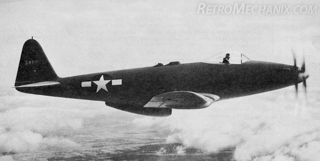
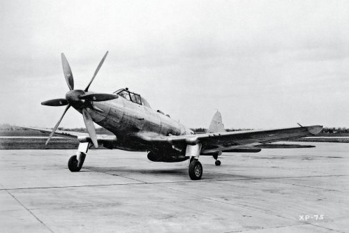
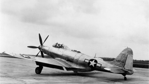
It contains numerous high resolution detail photos and drawings of this flawed but not entirely unappealing aircraft, one of a handful of types powered by the mighty 24 cylinder Allison V-3420. Many of the photos are heavily retouched and portray an interesting intermediate stage between the original XP-75 and the final P-75A, retaining the Douglas-style tail of the former but having the bubble canopy of the latter. Ideal information for the modeler, historian, or general enthusiast wishing to get an in depth look at GM's failed foray into fighter aircraft design.
-Jared
Just posted a new article at RetroMechanix.com presenting a very rare 51 page document on the Fisher P-75 Eagle:
It contains numerous high resolution detail photos and drawings of this flawed but not entirely unappealing aircraft, one of a handful of types powered by the mighty 24 cylinder Allison V-3420. Many of the photos are heavily retouched and portray an interesting intermediate stage between the original XP-75 and the final P-75A, retaining the Douglas-style tail of the former but having the bubble canopy of the latter. Ideal information for the modeler, historian, or general enthusiast wishing to get an in depth look at GM's failed foray into fighter aircraft design.
-Jared
XP67_Moonbat
ACCESS: Top Secret
- Joined
- 16 January 2008
- Messages
- 2,271
- Reaction score
- 544
Jared, you rock dude!
convairxf92
The Original Landspeeder
- Joined
- 31 May 2009
- Messages
- 39
- Reaction score
- 5
- Joined
- 22 April 2012
- Messages
- 2,258
- Reaction score
- 2,309
Synchronising 4 machine guns to fire through a 6 bladed contra-rotating propeller must have been fun! That said, the 10 .50 cal armament would have been devastating. It would have been interesting to see P-75's flying with B-39s (same engine).
pathology_doc
ACCESS: Top Secret
- Joined
- 6 June 2008
- Messages
- 1,587
- Reaction score
- 1,510
sealordlawrence said:Synchronising 4 machine guns to fire through a 6 bladed contra-rotating propeller must have been fun! That said, the 10 .50 cal armament would have been devastating.
One must ask oneself - with the unavoidable drop in rate of fire from the synchronised guns (because they can't be firing all the time), would one even get the same rounds per minute into the sky as the P-47 could with two less barrels?
- Joined
- 25 July 2007
- Messages
- 4,299
- Reaction score
- 4,197
Archibald said:Could that machine have be re-engined with a Sabre engine ?
Power would be about right but the shafting would be completely different.
http://www.enginehistory.org/Gallery/JimBuckel/Allison%20V-3420%20for%20Fisher%20P-75A%20Eagle%201-17.JPG
- Joined
- 8 March 2009
- Messages
- 1,056
- Reaction score
- 1,299
Re: Fisher P-75 Eagle Brochure from May 1944
Thank you!!!
In one fell swoop you have not only reignited my interest in making an accurate version of this aircraft for xplane, but also provided me with all the data I was more or less missing. Once a few other projects are done, that is.
jzichek said:Just posted a new article at RetroMechanix.com presenting a very rare 51 page document on the Fisher P-75 Eagle:
It contains numerous high resolution detail photos and drawings of this flawed but not entirely unappealing aircraft, one of a handful of types powered by the mighty 24 cylinder Allison V-3420. Many of the photos are heavily retouched and portray an interesting intermediate stage between the original XP-75 and the final P-75A, retaining the Douglas-style tail of the former but having the bubble canopy of the latter. Ideal information for the modeler, historian, or general enthusiast wishing to get an in depth look at GM's failed foray into fighter aircraft design.
-Jared
Thank you!!!
In one fell swoop you have not only reignited my interest in making an accurate version of this aircraft for xplane, but also provided me with all the data I was more or less missing. Once a few other projects are done, that is.
Kevin Renner
ACCESS: Confidential
- Joined
- 6 November 2007
- Messages
- 102
- Reaction score
- 12
As I understand it GM proposed this abbortion simply to get out of producing B-29 engine nacalles
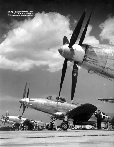
Does anyone know what was presumably being tested here with the probes(?) behind the props:

BTW, here's another photo without said probes:

- Joined
- 2 August 2006
- Messages
- 3,256
- Reaction score
- 1,529
It's a rake to get readings behind the entire disk of the propeller. They were probably using it to test the efficiency of the propellers. By measuring the pressure distribution they can determine the velocity profile of the airflow through propeller disk.
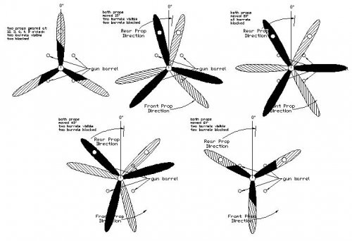
pathology_doc said:sealordlawrence said:Synchronising 4 machine guns to fire through a 6 bladed contra-rotating propeller must have been fun! That said, the 10 .50 cal armament would have been devastating.One must ask oneself - with the unavoidable drop in rate of fire from the synchronised guns (because they can't be firing all the time), would one even get the same rounds per minute into the sky as the P-47 could with two less barrels?Johnbr said:I would love to see how they did it.
Not as difficult as you might think. I worked it out some time ago by drawing it in my AutoCAD. As simply as possible, the props were geared in the remote speed reduction unit so would be 'timed' to the gun synchronization. It would just be like it had just one 3-blade prop. I've even worked this out for two 4-blade contra-prop arrangement. The diagram below show the blades only moving 60 degrees of rotation, so times this by three for one complete rotation.
Attachments
- Joined
- 19 July 2016
- Messages
- 4,285
- Reaction score
- 3,466
http://retromechanix.com/fisher-p-75-advance-descriptive-data-may-20-1944/nggallery/image/image-791
- Joined
- 8 March 2009
- Messages
- 1,056
- Reaction score
- 1,299
Yep, its a rake for testing. There was quite of bit of testing done both by Fisher and NACA.
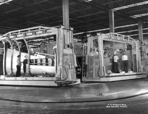
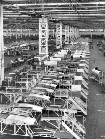
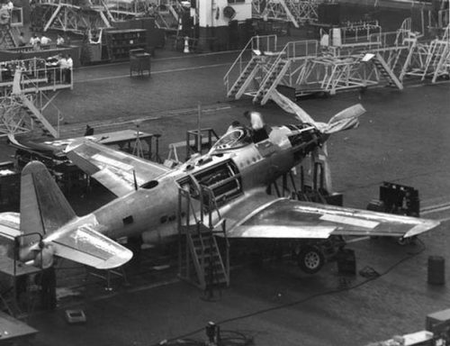
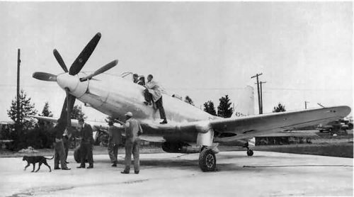
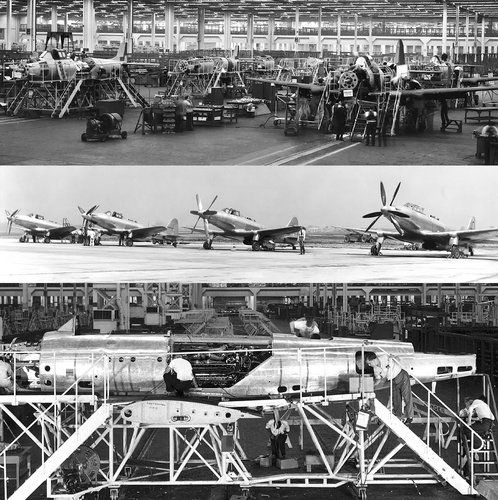
Here are some photos I've collected. First few are the intermediate design canopy, the last showing the assembly lines and jigs/tooling
Generally, a drop of 10/15% is what I've read for guns firing through a prop disk. So about half a guns fire is lost in the case of a P-75, so better than the P-47s 8 guns in the wing.
Attachments
-
 showimage (1).jpg55 KB · Views: 287
 -
 showimage (3).jpg51.2 KB · Views: 256
 -
 showimage (4).jpg48.7 KB · Views: 278
 -
 showimage (7).jpg46.5 KB · Views: 320
 -
 general-motors-p-75-p-75a-eagle-photo-print-3.jpg66 KB · Views: 585
 -
 kl 04-2013 P-75 Eagle (04).jpg.5857186.jpg83 KB · Views: 568
 -
 kjhkh.jpg379.1 KB · Views: 587
 -
 9b80432738b338699aaf1c36af0cc54b.jpg348 KB · Views: 615
Sherman Tank
I don't want to change my personal text
- Joined
- 14 October 2016
- Messages
- 235
- Reaction score
- 211
Does anyone know if the oft-told story that Fisher and GM created the P-75 was to avoid having their factory assigned to build B-29s in any way true? I suspect it isn't because it doesn't make much sense but I've never seen evidence either way besides anecdote.
I don't know. But the story makes perfect sense (of a sort). Commercial motives and profiteering were common enough in WW2, as they were in wars before and after. A native design using its own engines (Allison was a GM subsidiary) would have offered higher profits than licensing a Curtiss-Wright powered, Boeing designed airplane.Sherman Tank said:Does anyone know if the oft-told story that Fisher and GM created the P-75 was to avoid having their factory assigned to build B-29s in any way true? I suspect it isn't because it doesn't make much sense but I've never seen evidence either way besides anecdote.
Colonial-Marine
UAVs are now friend, drones are the real enemy.
- Joined
- 5 October 2009
- Messages
- 1,474
- Reaction score
- 1,327
The P-75 to me is quite a fascinating aircraft especially in its final form where it was a new airplane versus one made from various parts of other aircraft. It's a shame the final product failed to meet the original specifications by such a large degree.
Did Fisher have any plans for an XP-75B or P-75B to make up some of the lost performance? Was there any avenue to do so other than increasing engine power?
Did Fisher have any plans for an XP-75B or P-75B to make up some of the lost performance? Was there any avenue to do so other than increasing engine power?
Last edited:
No , all issues was fixed with a great delay of flight of P-75A . In anyway scenario was changed and there were aircraft like P-38 with an awesome range .The P-75 to me is quite a fascinating aircraft, in it's final form where it was a new airplane (versus one made from various parts of other aircraft). It's a shame the final product failed to meet the original specifications by such a large degree.
Did Fisher have any plans for an XP-75B or P-75B to make up some of the lost performance? Was there any avenue to do so other than increasing engine power?
windswords
ACCESS: Secret
- Joined
- 19 May 2009
- Messages
- 389
- Reaction score
- 218
blackkite
Don't laugh, don't cry, don't even curse, but.....
- Joined
- 31 May 2007
- Messages
- 8,819
- Reaction score
- 7,718
Hi!
Fisher P-75A Eagle
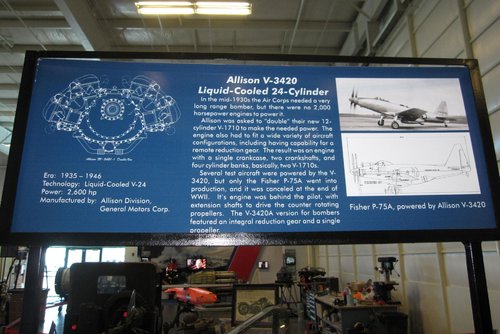
The Fisher Body Division of General Motors developed the P-75 Eagle to fill an urgent need for an interceptor early in World War II. The original P-75 design incorporated the most powerful inline
www.nationalmuseum.af.mil
Attachments
archipeppe
ACCESS: Top Secret
- Joined
- 18 October 2007
- Messages
- 2,431
- Reaction score
- 3,152
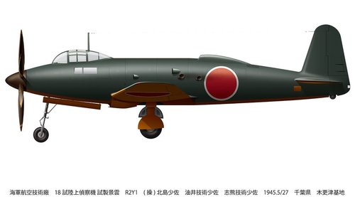
Another aircraft quite similiar to XP-75 is the Piaggio P-119.


- Joined
- 8 March 2009
- Messages
- 1,056
- Reaction score
- 1,299
.
Attachments
-
 kl 04-2013 P-75 Eagle (07).jpg.5857222.jpg113.5 KB · Views: 174
 -
 P_75A_44_44553_01_large.jpg202.3 KB · Views: 169
 -
 p-75.jpg23.6 KB · Views: 170
 -
 9c5201ec333076418fd9eef28cd68185.jpg46.5 KB · Views: 170
 -
 4564344013_944fc95fb7_o.jpg23.4 KB · Views: 160
 -
 5022048160_56c07c4721_o.jpg40.2 KB · Views: 153
 -
 5022048178_570b55eaa6_o.jpg74.1 KB · Views: 160
 -
 27930870883_3b14c7498d_o.jpg50.2 KB · Views: 190
blackkite
Don't laugh, don't cry, don't even curse, but.....
- Joined
- 31 May 2007
- Messages
- 8,819
- Reaction score
- 7,718

WJPearce
ACCESS: Confidential
- Joined
- 21 March 2008
- Messages
- 63
- Reaction score
- 37
I can understand the radiator position of this aircraft.
But..............
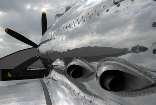
Perhaps this picture shows ram air intake and exhaust nozzle. Inline..........
The P-75 had air-cooled exhaust manifolds. A jacket surrounded the exhaust manifold and air was fed through that jacket. The air entered through the ram-air scoop and exited via the area around the exhaust pipes.
blackkite
Don't laugh, don't cry, don't even curse, but.....
- Joined
- 31 May 2007
- Messages
- 8,819
- Reaction score
- 7,718
Oh thanks a lot. What a surprising exhaust system!!
According to top early model picture, two ram air intakes were located behind the wind shield and integrated to exhaust nozzle cover.
24 exhaust nozzles were integrated 8 by exhaust manifolds.
According to top early model picture, two ram air intakes were located behind the wind shield and integrated to exhaust nozzle cover.
24 exhaust nozzles were integrated 8 by exhaust manifolds.
Attachments

Last edited:
blackkite
Don't laugh, don't cry, don't even curse, but.....
- Joined
- 31 May 2007
- Messages
- 8,819
- Reaction score
- 7,718

blackkite
Don't laugh, don't cry, don't even curse, but.....
- Joined
- 31 May 2007
- Messages
- 8,819
- Reaction score
- 7,718
blackkite
Don't laugh, don't cry, don't even curse, but.....
- Joined
- 31 May 2007
- Messages
- 8,819
- Reaction score
- 7,718
Hi!
"The 2,600 hp (1,939 kW) Allison V-3420-19 engine with a two-stage supercharger was positioned in the fuselage behind the pilot. Each of the engine’s four cylinder banks had an air-cooled exhaust manifold with two exhaust stacks protruding out of the fuselage............"

 oldmachinepress.com
"The 2,600 hp (1,939 kW) Allison V-3420-19 engine with a two-stage supercharger was positioned in the fuselage behind the pilot. Each of the engine’s four cylinder banks had an air-cooled exhaust manifold with two exhaust stacks protruding out of the fuselage............"
Fisher (General Motors) P-75 Eagle Fighter
The Fisher XP-75 was an ambitious attempt to create a world-class WWII fighter utilizing many existing components. In the end, it was a complex and expensive aircraft with mediocre performance.
oldmachinepress.com
Attachments
Last edited:
WJPearce
ACCESS: Confidential
- Joined
- 21 March 2008
- Messages
- 63
- Reaction score
- 37
I am not 100% certain with the information below, but I believe it is correct.
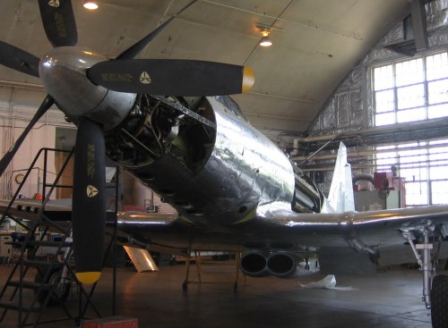
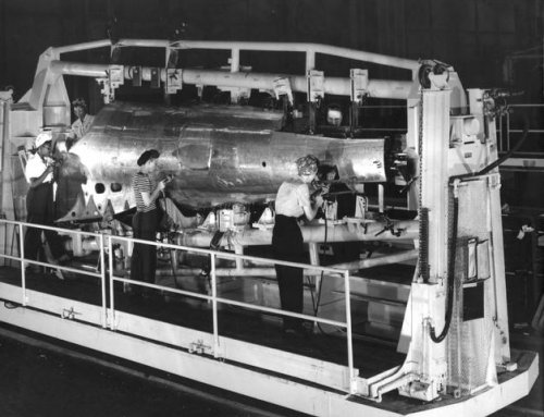
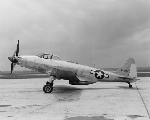
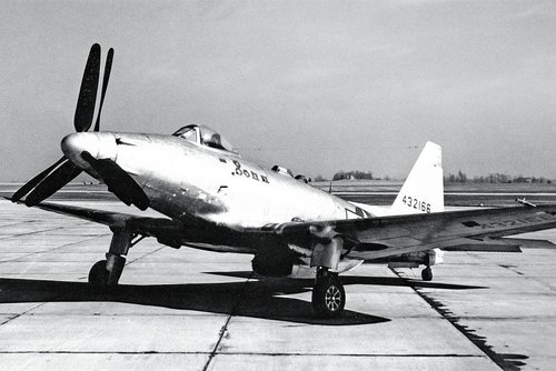
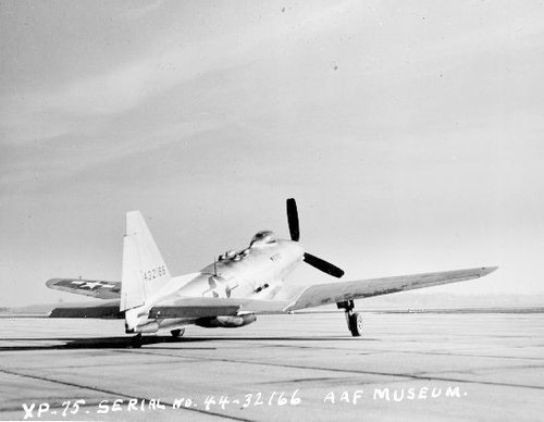
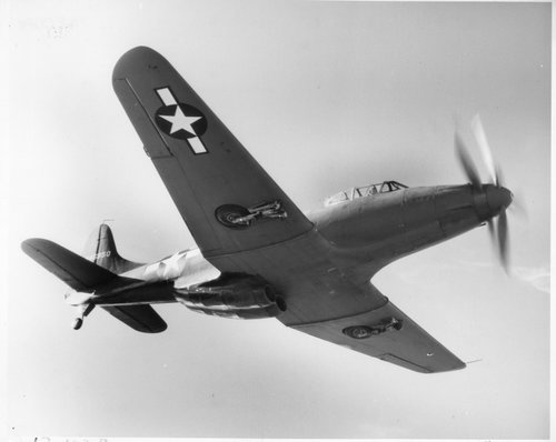
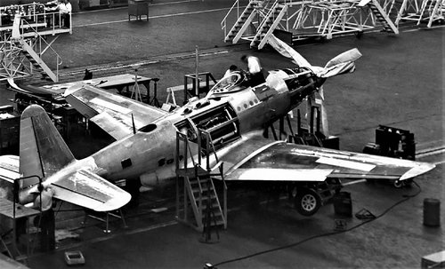
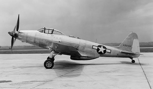
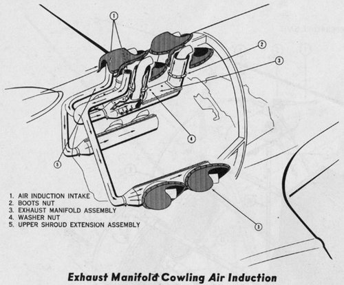
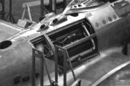
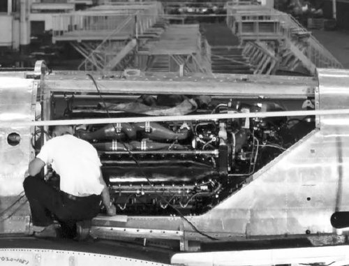
The early XP-75s took in air for exhaust cooling from the top ducts and distributed it to all manifolds. See the drawing. The early XP-75s did not have the scoop on the sides. See the image of 44-32162, which was the second of six aircraft that made up the second batch (XP-75A) of prototype aircraft. Also, the exhaust cooling jacket as seen in the drawing is visible in the image of an XP-75A under construction. This is either 44-32165 or 44-32166, the last two aircraft of the second batch.
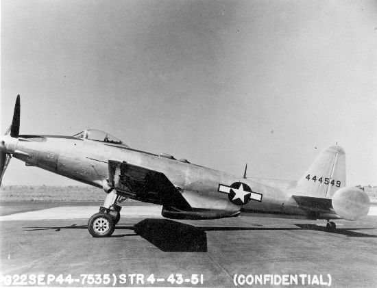
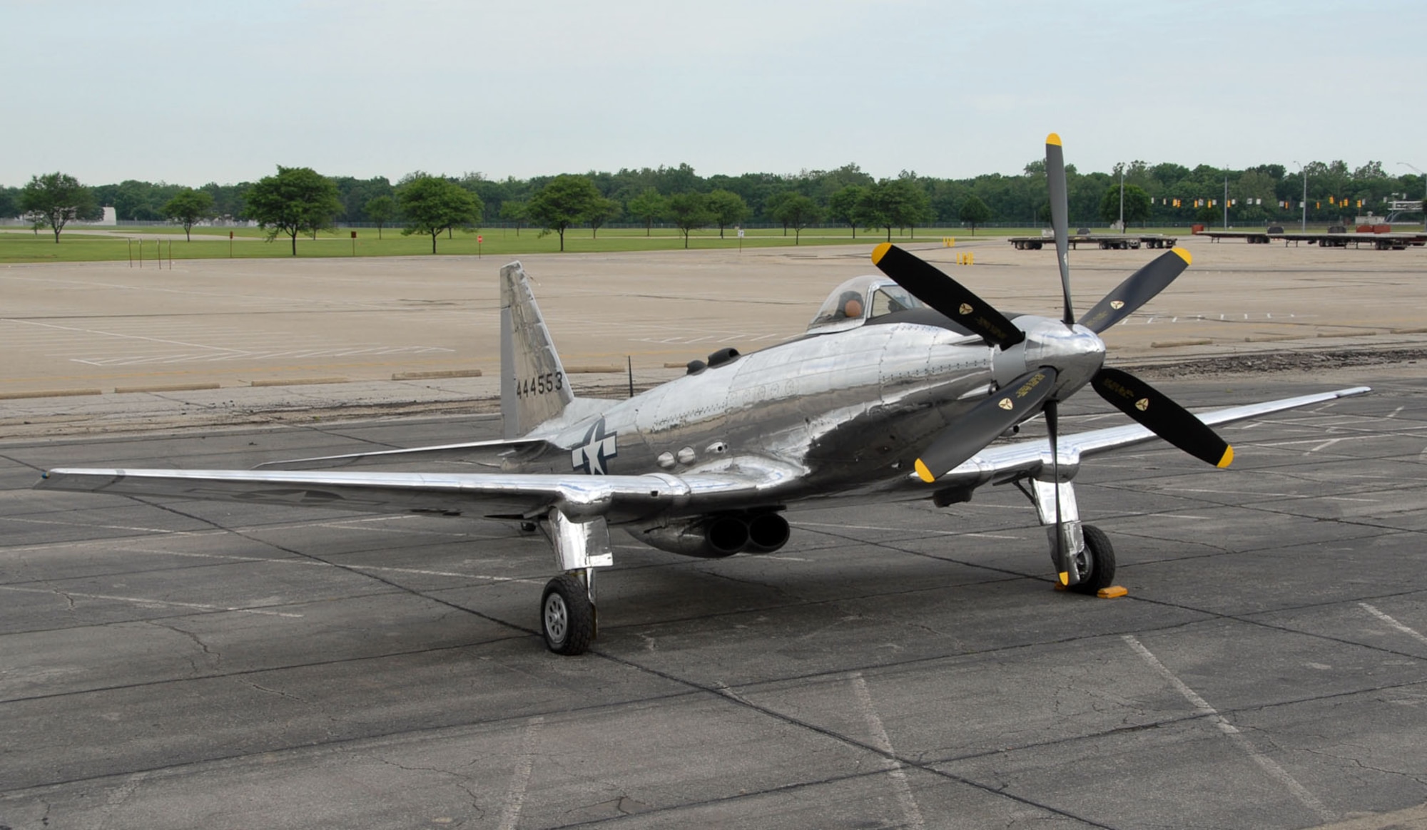
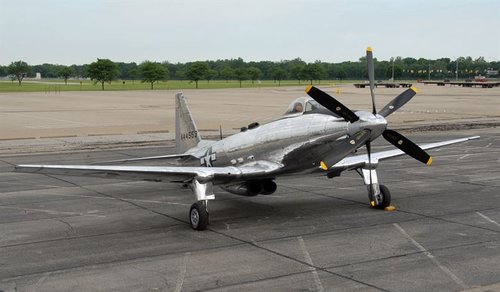
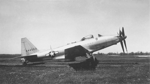
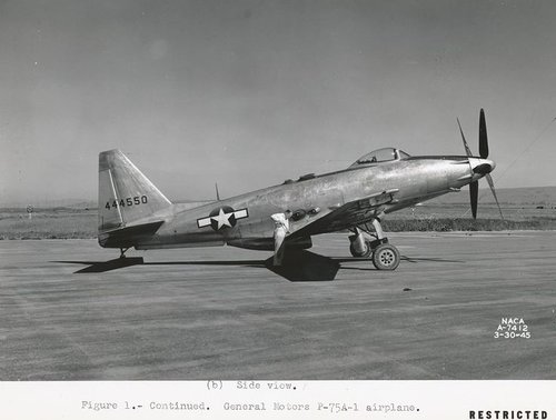
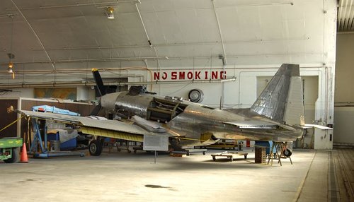
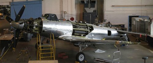
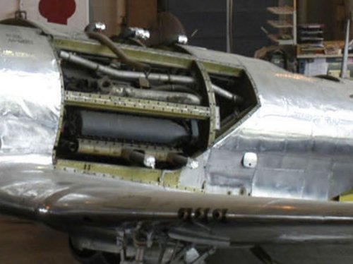
The P-75A production aircraft (44-44549 to 44-44553) did have the side scoop. In the image of 44-44553 under restoration, I believe you can see the pipe just forward of the side exhaust manifold that would connect to the scoop in the cowling.
All the P-75s used the V-3420-B engine that had a two-stage supercharger. Air for the engine was fed into the impeller of the first stage at the back of the engine. I think the air for the engine came in via the belly scoop, perhaps on the right side before the coolant radiator.
The early XP-75s took in air for exhaust cooling from the top ducts and distributed it to all manifolds. See the drawing. The early XP-75s did not have the scoop on the sides. See the image of 44-32162, which was the second of six aircraft that made up the second batch (XP-75A) of prototype aircraft. Also, the exhaust cooling jacket as seen in the drawing is visible in the image of an XP-75A under construction. This is either 44-32165 or 44-32166, the last two aircraft of the second batch.
The P-75A production aircraft (44-44549 to 44-44553) did have the side scoop. In the image of 44-44553 under restoration, I believe you can see the pipe just forward of the side exhaust manifold that would connect to the scoop in the cowling.
All the P-75s used the V-3420-B engine that had a two-stage supercharger. Air for the engine was fed into the impeller of the first stage at the back of the engine. I think the air for the engine came in via the belly scoop, perhaps on the right side before the coolant radiator.
Attachments
blackkite
Don't laugh, don't cry, don't even curse, but.....
- Joined
- 31 May 2007
- Messages
- 8,819
- Reaction score
- 7,718
Oh I see!! Thank you very much for excellent and detailed information.
Without your information, perhaps I can't understand this system forever.
Without your information, perhaps I can't understand this system forever.
Last edited:
- Joined
- 19 July 2016
- Messages
- 4,285
- Reaction score
- 3,466
Just for the sake of asking, how would the P-75a have fared against the TA-152h series in the escort role?
blackkite
Don't laugh, don't cry, don't even curse, but.....
- Joined
- 31 May 2007
- Messages
- 8,819
- Reaction score
- 7,718
Very hard question indeed.Just for the sake of asking, how would the P-75a have fared against the TA-152h series in the escort role?
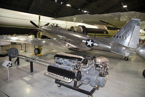
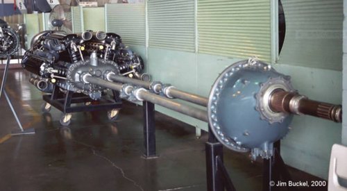
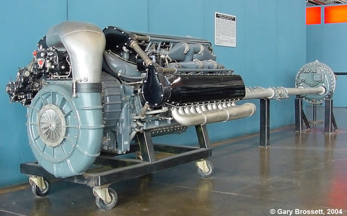
"This V-3420-B was the type installed in the Fisher XP-75. About 15 ft (4.6 m) of shafting separated the engine from the gear reduction. Note the much larger supercharger compared to the image of the V-3420-A engine. The V-3420-B used a two-stage supercharger and no turbosupercharger. (Gary Brossett image via the Aircraft Engine Historical Society)"
I can see two stage supercharger.

Allison V-3420 24-Cylinder Aircraft Engine
The Allison V-3420 24-cylinder engine was more than just two coupled V-1710s. The large engine showed promise, but other priorities and a lack of aircraft applications regulated the V-3420 to obscu…
oldmachinepress.com
Attachments

Last edited:
blackkite
Don't laugh, don't cry, don't even curse, but.....
- Joined
- 31 May 2007
- Messages
- 8,819
- Reaction score
- 7,718
WJPearce-san said that
"All the P-75s used the V-3420-B engine that had a two-stage supercharger. Air for the engine was fed into the impeller of the first stage at the back of the engine.I think the air for the engine came in via the belly scoop, perhaps on the right side before the coolant radiator."
I think this is excellent opinion.
Ducting from ram air intake to supercharger is easy.
Sorry all of my opinions are perfectly mistake.
Attachments
Speaking of the Merlin vs. Allison thread
I was just wandering around on Google and came across something I never knew existed. http://en.m.wikipedia.org/wiki/Allison_V-3420 Considering the weight of the Griffon compared to the weight of this, and considering the horsepower of the two, would planes such as PM benefit with the...
www.aafo.com
Attachments
Last edited:
WJPearce
ACCESS: Confidential
- Joined
- 21 March 2008
- Messages
- 63
- Reaction score
- 37
Glad I could help, blackkite. There is a lot of missing information on the XP-75.
I think the Ta 152H would have outclassed the P-75A. The Ta 152H was faster, especially at altitude, and had a higher ceiling. I think the Ta 152 was designed specifically for high-altitude, while the P-75 was a long-range fighter. The Ta 152 was a much more conventional design, and no one seemed to like how the P-75 flew, noting it as unstable and sluggish.
A few other points on the engine installation that led me to believe the info I posted previously.
In the engine installation image, note that there is a fair amount of room above the engine that could accommodate an induction system. However, the upper exhaust manifolds are not installed, and they would take up some of that room. Also, space is limited toward the rear of the engine were the induction pipe connects the first (auxiliary) stage and second (engine) stage superchargers. I believe an intercooler was planned for this location, and that would have further limited the space.
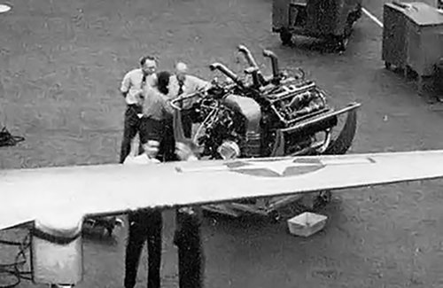
The image of the engine behind the P-75 wing shows the upper exhaust manifolds attached. There is enough room between them for an induction pipe, but this pipe would have been surrounded by the hot exhaust. Also, the induction would have to connect to the circular cover at the back of the engine, which is the auxiliary supercharger. This would require a fair amount of room and two 90-degree bends. It makes more sense (to me) to bring in air from the belly scoop, but I have not seen any images that confirm this.
The engine image provides a good view of the inlet/impeller of the auxiliary supercharger. Air existed the first stage via the silver pipe above the engine. This is where an intercooler was to be incorporated. The air was then fed through an injection carburetor and into the second, engine supercharger. The engine supercharger was coupled to the engine’s right crankshaft, and you can see its round housing with the horizontal ribs. You can also see the main induction manifold leading from the engine supercharger to between the right engine Vee.
The placement of the supercharger favors the right belly scoop providing induction air. Also, the right scoop just had a coolant radiator, while the left scoop had a coolant radiator and an oil cooler. Lastly, the exhaust manifolds on the display engine are not the same as those installed on the P-75.
I realize some of it is speculation, but it is the best I have.
I think the Ta 152H would have outclassed the P-75A. The Ta 152H was faster, especially at altitude, and had a higher ceiling. I think the Ta 152 was designed specifically for high-altitude, while the P-75 was a long-range fighter. The Ta 152 was a much more conventional design, and no one seemed to like how the P-75 flew, noting it as unstable and sluggish.
A few other points on the engine installation that led me to believe the info I posted previously.
In the engine installation image, note that there is a fair amount of room above the engine that could accommodate an induction system. However, the upper exhaust manifolds are not installed, and they would take up some of that room. Also, space is limited toward the rear of the engine were the induction pipe connects the first (auxiliary) stage and second (engine) stage superchargers. I believe an intercooler was planned for this location, and that would have further limited the space.
The image of the engine behind the P-75 wing shows the upper exhaust manifolds attached. There is enough room between them for an induction pipe, but this pipe would have been surrounded by the hot exhaust. Also, the induction would have to connect to the circular cover at the back of the engine, which is the auxiliary supercharger. This would require a fair amount of room and two 90-degree bends. It makes more sense (to me) to bring in air from the belly scoop, but I have not seen any images that confirm this.
The engine image provides a good view of the inlet/impeller of the auxiliary supercharger. Air existed the first stage via the silver pipe above the engine. This is where an intercooler was to be incorporated. The air was then fed through an injection carburetor and into the second, engine supercharger. The engine supercharger was coupled to the engine’s right crankshaft, and you can see its round housing with the horizontal ribs. You can also see the main induction manifold leading from the engine supercharger to between the right engine Vee.
The placement of the supercharger favors the right belly scoop providing induction air. Also, the right scoop just had a coolant radiator, while the left scoop had a coolant radiator and an oil cooler. Lastly, the exhaust manifolds on the display engine are not the same as those installed on the P-75.
I realize some of it is speculation, but it is the best I have.
Attachments
Similar threads
-
-

-
-
 Christopher AG-1 and Timm AG-2 assault gliders
- Started by Stargazer
- Replies: 4
-