Glad I could help, blackkite. There is a lot of missing information on the XP-75.

I think the Ta 152H would have outclassed the P-75A. The Ta 152H was faster, especially at altitude, and had a higher ceiling. I think the Ta 152 was designed specifically for high-altitude, while the P-75 was a long-range fighter. The Ta 152 was a much more conventional design, and no one seemed to like how the P-75 flew, noting it as unstable and sluggish.

A few other points on the engine installation that led me to believe the info I posted previously.

In the engine installation image, note that there is a fair amount of room above the engine that could accommodate an induction system. However, the upper exhaust manifolds are not installed, and they would take up some of that room. Also, space is limited toward the rear of the engine were the induction pipe connects the first (auxiliary) stage and second (engine) stage superchargers. I believe an intercooler was planned for this location, and that would have further limited the space.

The image of the engine behind the P-75 wing shows the upper exhaust manifolds attached. There is enough room between them for an induction pipe, but this pipe would have been surrounded by the hot exhaust. Also, the induction would have to connect to the circular cover at the back of the engine, which is the auxiliary supercharger. This would require a fair amount of room and two 90-degree bends. It makes more sense (to me) to bring in air from the belly scoop, but I have not seen any images that confirm this.

The engine image provides a good view of the inlet/impeller of the auxiliary supercharger. Air existed the first stage via the silver pipe above the engine. This is where an intercooler was to be incorporated. The air was then fed through an injection carburetor and into the second, engine supercharger. The engine supercharger was coupled to the engine’s right crankshaft, and you can see its round housing with the horizontal ribs. You can also see the main induction manifold leading from the engine supercharger to between the right engine Vee.

The placement of the supercharger favors the right belly scoop providing induction air. Also, the right scoop just had a coolant radiator, while the left scoop had a coolant radiator and an oil cooler. Lastly, the exhaust manifolds on the display engine are not the same as those installed on the P-75.

I realize some of it is speculation, but it is the best I have.
Thanks for excellent and detailed opinion again.
 
I feel fuselage bottom left and right air intake inner shape are little different.

P-75 slide show.
 

Attachments

  • front.JPG
    front.JPG
    723.7 KB · Views: 129
  • fuselage bottom right air intake.jpg
    fuselage bottom right air intake.jpg
    79.3 KB · Views: 87
Last edited:
Please check this video from 2minutes after start by enlarged mode and you can see the difference between two air intakes very clearly.
As if you see hole in right side(starboard side) air intake and you see radiator front face in left side(port side) air intake,


Attachments

  • air intake.JPG
    air intake.JPG
    218.9 KB · Views: 175
Last edited:
Hi!

"A two-section scoop was located under the fuselage, just behind the wings. The left section held an oil radiator, and coolant radiators were positioned in both the left and right sections."

So right section had some room for ram air intake?
 

Attachments

  • FisherP75eagleColour2a.jpg
    FisherP75eagleColour2a.jpg
    639.5 KB · Views: 183
  • GM_XP-75_04.jpg
    GM_XP-75_04.jpg
    89.6 KB · Views: 167
  • GM_XP-75_05.jpg
    GM_XP-75_05.jpg
    78.5 KB · Views: 152
  • p-57a side.JPG
    p-57a side.JPG
    76.7 KB · Views: 144
Last edited:
Fisher P-75 Eagle Brochure from May 1944

Just posted a new article at RetroMechanix.com presenting a very rare 51 page document on the Fisher P-75 Eagle:

5757609564_aabeab629c_o.jpg


It contains numerous high resolution detail photos and drawings of this flawed but not entirely unappealing aircraft, one of a handful of types powered by the mighty 24 cylinder Allison V-3420. Many of the photos are heavily retouched and portray an interesting intermediate stage between the original XP-75 and the final P-75A, retaining the Douglas-style tail of the former but having the bubble canopy of the latter. Ideal information for the modeler, historian, or general enthusiast wishing to get an in depth look at GM's failed foray into fighter aircraft design.

-Jared
Jared,

Can I get a copy of that brochure? Been looking all over for it. Thought it might be on your Patreon site that I recently subscribed to. Either way, keep up the great work!

Regards, Jim
 
Silly question of the day, could the aircraft be returned to flight status? Unlikely I know and a purely rhetorical question.
 
With enough money, anything can be returned to flight status. Would I like to see that? No. Last of the bread airframe should stay in museums. Case in point, the Northrop N9. Maybe it should never had left the landing pattern. Now, sadly, it's too late.
 
Hi,

Not as difficult as you might think. I worked it out some time ago by drawing it in my AutoCAD. As simply as possible, the props were geared in the remote speed reduction unit so would be 'timed' to the gun synchronization. It would just be like it had just one 3-blade prop. I've even worked this out for two 4-blade contra-prop arrangement. The diagram below show the blades only moving 60 degrees of rotation, so times this by three for one complete rotation.

The problem with synchronization is that the mechanical synchronizers of the era synchronized the release of the firing pin and no the transit of the bullet through the propeller rotation plane. As there were several sources of random variation, the most important probably being the delay between the firing pin strike and the ignition of the main propellant charge, and one systematic variation unaccounted for by the synchronizer - engine speed -, the projectile transition point could actually be anywhere on an arc section.

If you've seen sychronizer test targets that were mounted on the propeller, this arc section is actually visible on them as a series of bullet holes. I think there are photographs showing Anthony Fokker with such test targets, and they were used in the same way by the Luftwaffe in WW2. The term for this test was "Auswanderungsschießen" ... "creep firing (test)" - because the bullet holes crept along arc when rpm was changed.

The available arc section and thus the allowable rpm range and mechanism/ammunition tolerance range was much smaller with a contra-rotating propeller because the second set of blades intruded into the "clear" area from the opposite direction.

If you're faimiliar with the Heinkel He 119 ... Heinkel actually projected a successor with the same layout, including a contra-rotating propeller, as a reconnaissance aircraft. When the Luftwaffe asked for a night-fighter instead, Heinkel switched the He 219 over to the conventional twin-engine layout since synchronization would have been really awkward with the contra-prop - and German synchronization system used electric priming, which generally was much more practical than the mechanical systems used by the US.

Here's a picture of the synchronizer used on the XP-75 ... the document it's in has some more (mostly non-technical) information on the history of the XP-75:


Regards,

Henning (HoHun)
 
Hi,

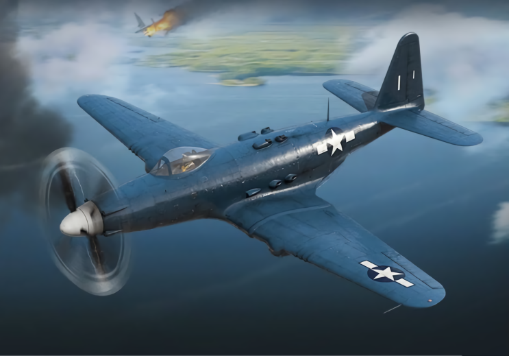
Just for the sake of asking, how would the P-75a have fared against the TA-152h series in the escort role?

I don't have all that much data on the engine used, and the reported performance figures for the P-75 are a bit confusing with regard to what would have been the actual critical altitude of the engine to be used in the production version.

Additionally, the P-75 during its life seems to have been subject to a certain increase in flying weight, and I am not entirely sure what would have been typical for a production version.

The USAF museum has this great panoramic picture of the cockpit of its surviving P-75:


There's a placard on the panel, "Restrictions - 17264 lbs - 5.25 G - 400 I.A.S." ... now undoubtly this applied to the prototype, but that probably implies it could be loaded to even higher take-off weights than that.

A P-47D-25RE with the large internal fuel tank weighed in at around 14500 lbs, with 17500 lbs being indicated as the "recorded limit" (on the "Tactical Planning and Characteristics Chart", p. 31, 26 May 1944. The maximum fuel capacity was 370 US gallons internal plus 410 US gallons external.

As indicated on the fuel cock/fuel indicators in the above P-75 cockpit foto, the P-75 has a main tank of 435 US gallons plus two wing tanks of a combined 120 US gallons internal, and two auxiliary tanks of unspecified capacity. I am not even sure if they're internal or external ... they're labeled on the fuel cock, but there seems to be no fuzel gauge for them. (US terminology did not always differentiate between drop tanks and internal tanks, I believe.)

The P-47 had 2600 HP available, the P-75 maybe 2800 HP. The P-75 was a bit larger and heavier, so power loading might have been fairly similar. However, the P-47 retained its power up to very high altitudes, and I am not sure the same applies to the P-75 (for which I have insufficient data).

Accordingly, I'd say that the P-75, even if it had been cured of all of its intitial problems, would not have been much of an improvement, if any, over the P-47D.

Since the P-47D is pretty much a known quantity, you might already have an idea of how it compares to the Ta 152H you were actually asking for :)

Regards,

Henning (HoHun)
 
Thanks, appreciated. I did not think to compare the P47D but then also ignored the low altitude variant of the Ta-152 which might be closer to the P-47D. Blinkers.....
 
Does anyone know what was the avionics setup of the P-75s (COM, NAV, IFF, gunsight electronics, etc.)?
 
Hi Yahya,

Does anyone know what was the avionics setup of the P-75s (COM, NAV, IFF, gunsight electronics, etc.)?

According to an article by Alain Pelletier in "Le Fana d'Aviation", August 1996:

- N-9 gun sight
- N-6 gun cinecamera
- MN-26C or Y radio compass
- BC-1206-A ... https://aeroantique.com/de/products/bc-1206-receiver?variant=6452198965278
- SCR-522-A or SCR-274-N radio ... https://www.radionerds.com/index.php/SCR-522
- SCR-695-A IFF

Regards,

Henning (HoHun)
 
Hello HoHun,
Thank you very much indeed for the precise information. These pieces of avionics were popular at the time.

The SCR-522 was a cloned British VHF transceiver:

The SCR-274 Command Set a.k.a. the AN/ARC-5 was a longer range High Frequency radio:

The MN-26C was a nice piece of navigation equipment of that vintage:

The BC-1206 was a low frequency receiver to pick up eg. weather broadcasts. While it operated in the ADF radio spectrum, as far as I know, it was not connected to RMI as the MN-26 could do the job.

The SCR-695 contained a destruction explosive to be initiated by the pilot by pressing two buttons on the BC-765 switch box in case of emergency landing or ditching in enemy-held territory.
 

Attachments

  • 403.jpg
    403.jpg
    365 KB · Views: 44
Thank you. After all, I am not sure if the French author was right using the term 'conservateur de cap' while referring to the BC-1206.

The BC-1206A and BC-1206B were 200 to 400 kHz receivers made by Detrola as Model 438 and were powered from the 28V DC bus of the aircraft. These were simple receivers, and, as far as I know, they were not connected to the RMI at all. As I wrote above, the MN-26 radio compass could do the DF job.

A photo of a BC-1206A can be found here:


deliveryService


There were also the BC-1206C and BC-1206CM receivers, but made by Setchell-Carlson, Inc. as Model 524. The specs were identical. Photo from https://www.pa3esy.nl/military/us/air/BC1206/html/bc1206_set.html

_MG_5878.jpg
 
Hi Yahya,

The BC-1206A and BC-1206B were 200 to 400 kHz receivers made by Detrola as Model 438 and were powered from the 28V DC bus of the aircraft. These were simple receivers, and, as far as I know, they were not connected to the RMI at all. As I wrote above, the MN-26 radio compass could do the DF job.

From the German article I linked above, I suspect that its purpose in navigation was to pick up signals from Lorenz beams ... those with the "AN" morse signals adding to a continuous tone if you were in the center between the two offset beams. Not sure what they were called in the US, but I think they were used for navigation on civilian airways in the states before WW2.

Regards,

Henning (HoHun)
 
Hi Henning,

Well, the BC-1206 had only three connectors in the rear, (+) and (-) for 28V DC (i.e. Gleichstrom), and an antenna wire connector. These sets used no directional antenna like a rotatable magnetic loop that is used in semi-automatic radio compasses or ADFs, and they were not interfaced with RMIs. They resemble a commercial Long Wave radio that you probably have at home. Lorenz beams were a much more sophisticated system. So the BC-1206 sets were not suitable for radio navigation that we know. From what I learned from the web is that these receivers were commonly installed in the aircraft when they were ferried from a factory to the field, and in many occasions these were the only radio sets on-board even large airplanes. Unless visually seen by the ATC, the ferry pilot or WASP was to wave the wings during VFR flights, and then the tower responded on pre-arranged frequency between 200 and 400 kHz giving instructions or weather information if necessary. Otherwise, homing commands were sent in the Morse code to the pilot, which was in that era widely known in aviation and maritime services.

Here are some more hints:


This is a must-read:

 
Last edited:
Hi Yahya,

Well, the BC-1206 had only three connectors in the rear, (+) and (-) for 28V DC (i.e. Gleichstrom), and an antenna wire connector. These sets used no directional antenna like a rotatable magnetic loop that is used in semi-automatic radio compasses or ADFs, and they were not interfaced with RMIs.

Quite fascinating, thanks a lot for the links!

Don't they actually confirm the AN system functionality? If I understand this link correctly, all the directional magic happened in the ground transmitter antenna array: http://www.ase-museoedelpro.org/Mus...tary_navigation/LFR_receiver/LFR_receiver.pdf

Regards,

Henning (HoHun)
 
Last edited:
Hi Yahya,

And here is a map of such ground stations:

u_s_map_radio_ranges.gif

Thanks a lot, that's very cool stuff ... I was aware of the AN system with regard to its technology, but never had a clear idea of how it covered the US with airways! :)

Regards,

Henning (HoHun)
 
Mt understanding is that in order to avoid running in to someone on the same 'beam' pilots flying the inbound course would stay to the right by listening to the steady overlap of the A-N and a faint A or N in the background depending on the quadrant they were supposed to be in just right-of course. Outbound pilots did the same, but from the opposing quadrant.
 
Hi Dynoman,

Mt understanding is that in order to avoid running in to someone on the same 'beam' pilots flying the inbound course would stay to the right by listening to the steady overlap of the A-N and a faint A or N in the background depending on the quadrant they were supposed to be in just right-of course. Outbound pilots did the same, but from the opposing quadrant.

Are you sure of that? I just found this period manual, which outlines some peculiarities of the AN ranges that made me wonder about the resilience of the position information they provide:


Altitude separation would seem a more robust system. Of course, combining altitude and 'overlap bias' separation might be even more robust ... :)

Regards,

Henning (HoHun)
 
I think that you also have to consider cross wind, which may divert the aircraft from the course eg. into the "A" beam, and the temperamental propagation on Low Frequencies/Medium Frequencies, especially during stormy weather. All in all, the A-N system was state of an art in the 1930s and 1940s, but omnidirectional beacons and ADF would slightly add accuracy.
Mt understanding is that in order to avoid running in to someone on the same 'beam' pilots flying the inbound course would stay to the right by listening to the steady overlap of the A-N and a faint A or N in the background depending on the quadrant they were supposed to be in just right-of course. Outbound pilots did the same, but from the opposing quadrant.
 
Hi,


The problem with synchronization is that the mechanical synchronizers of the era synchronized the release of the firing pin and no the transit of the bullet through the propeller rotation plane. As there were several sources of random variation, the most important probably being the delay between the firing pin strike and the ignition of the main propellant charge, and one systematic variation unaccounted for by the synchronizer - engine speed -, the projectile transition point could actually be anywhere on an arc section.

If you've seen sychronizer test targets that were mounted on the propeller, this arc section is actually visible on them as a series of bullet holes. I think there are photographs showing Anthony Fokker with such test targets, and they were used in the same way by the Luftwaffe in WW2. The term for this test was "Auswanderungsschießen" ... "creep firing (test)" - because the bullet holes crept along arc when rpm was changed.

The available arc section and thus the allowable rpm range and mechanism/ammunition tolerance range was much smaller with a contra-rotating propeller because the second set of blades intruded into the "clear" area from the opposite direction.

If you're faimiliar with the Heinkel He 119 ... Heinkel actually projected a successor with the same layout, including a contra-rotating propeller, as a reconnaissance aircraft. When the Luftwaffe asked for a night-fighter instead, Heinkel switched the He 219 over to the conventional twin-engine layout since synchronization would have been really awkward with the contra-prop - and German synchronization system used electric priming, which generally was much more practical than the mechanical systems used by the US.

Here's a picture of the synchronizer used on the XP-75 ... the document it's in has some more (mostly non-technical) information on the history of the XP-75:


Regards,

Henning (HoHun)
The Germans used electrical rather than mechanical synchronization. In the case of the 7.92mm MG 17, the signal operated a solenoid that interrupted operation of the firing pin for the percussion primer. The 13mm MG 131, MG 151/20, MK 103 and MK 108 used
electrical primers, the synchronizer signal interrupted the current flow preventing ignition.

An electrical synchronizer would have worked for the P-75.
 
Hi jcf,

An electrical synchronizer would have worked for the P-75.

If you say "would", do you mean it had a mechanical synchronizer which didn't work?

Regards,

Henning (HoHun)
 
Back
Top Bottom