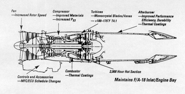
If I understand you correctly the rule of thumb to estimate maximum take-off weight is multiplying total aircraft volume by 1000 (1000 kg/m³).
Here’s an interesting set of NASA conceptual studies that will give you some good weight and volume breakdowns… the density seems closer to 500 kg/m3.
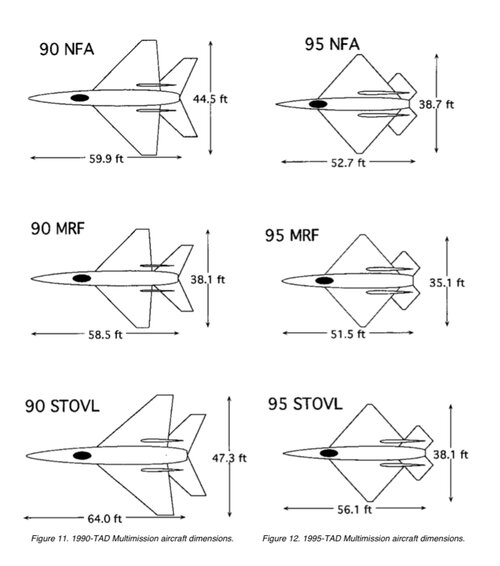
Future Carrier-based Tactical Aircraft Study (1996)
See in particular the multirole fighter “90 MRF” (p.107) and “95 MRF” (p.171) designs. Some of the assumptions seem a little optimistic but the 95 MRF should be relevant with its internal bays and 9t empty weight.
Thanks
@H_K , that's an interesting document for sure! I will read it as soon as I find some time...
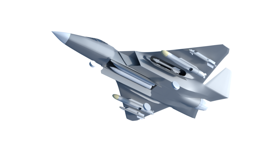
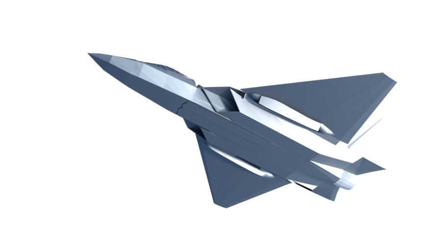
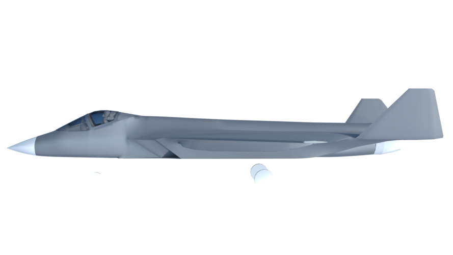
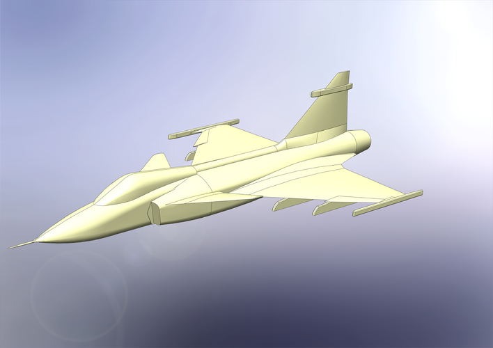
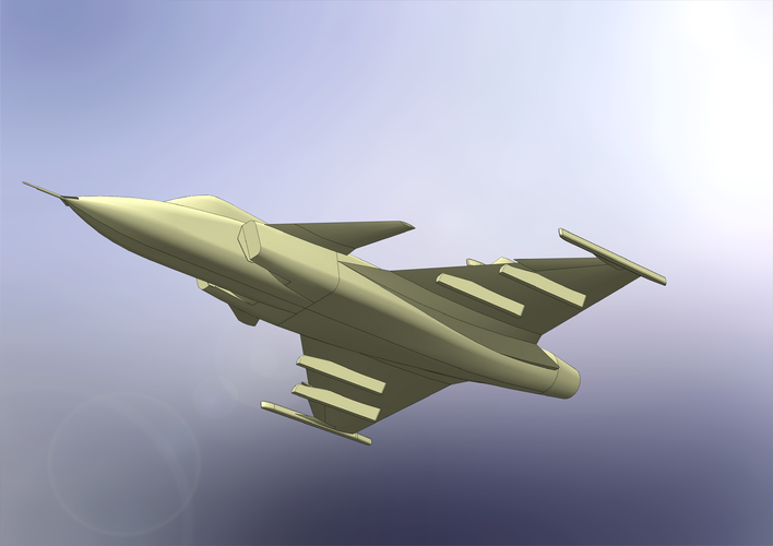
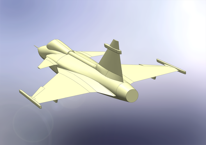
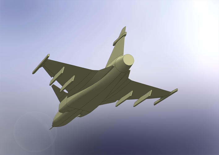
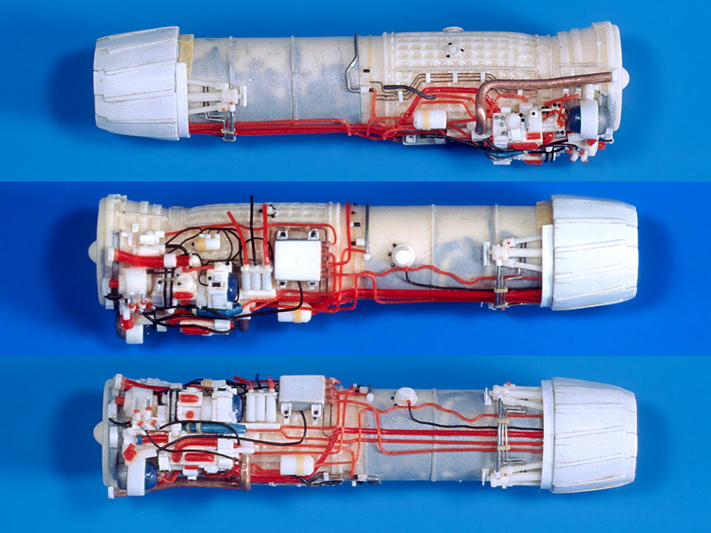
In the meantime I have created a CAD-model of the legacy Gripen. By doing that I can determine its volume an calculate the density. The CAD-model is not 100% accurate, but I'm confident it is more than enough for this purpose (see pics attached).
I can confirm the ~500 kg/m³ for maximum take off weight.
Here are the density numbers in reference to the CAD-model and the given specifications:
Total Aircraft Volume: 24,21 m³ (solid model, without any hollow space).
Empty Weight: 6622kg => 273,5 kg/m³
Max Weight: 14000kg => 578 kg/m³
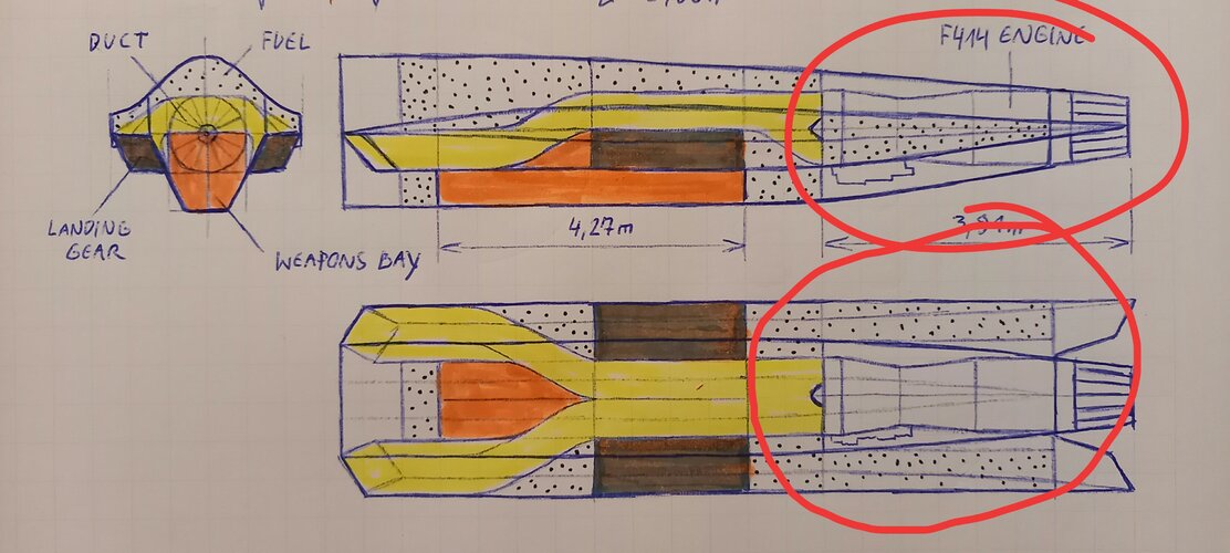
Hence, I will aim for approximatley 27 m³ of aircraft volume => Gripen's total volume (24,21 m³) + desired weapons bay (2,72 m³) = 26,93 m³. By using the 273,5 kg/m³ I get an empty weight of approximatley 7400 kg.
In conclosion, this aircraft is expected to have the following specs:
1) An internal weapons bay (2,72 m³) that can accomodate four AIM-120C (650 kg), or a mix of other ordnace up to ~1000 kg.
2) A fuel tank volume equivalent to the legacy Gripen (2820 l / 2270 kg).
3) An empty weight of 7600 kg, which is equivalent to the Gripen NG.
In regards of take off weight:
1) Loaded with four AIM-120C and full internal fuel: ~10,5 t (10520 kg).
2) Loaded with the maximum internal load and full internal fuel: ~11 t (10870 kg).
3) "Beast Mode": Whatever it can lift without tumbling
")
That sounds like useful capability IMHO.