VTOLicious

ACCESS: Top Secret
Senior Member
Joined
24 November 2008
Messages
1,333
Reaction score
1,677
XY: "A stealth fighter in the size of a Saab Gripen is impossible without compromising its performance to a point where it becomes useless".
Me: "Hold my beer..." :)

Everyone is welcome to join! But be aware, this is intended to be beyond napkin sketches. You may need some CAD skills or access to design software to be able to model complex geometries like serpentine ducts and to estimate your vehicle parameters, like fuselage volume, fuel tank volume, etc. However, it all starts with a sketch and you are welcome to post your ideas!

A discussion on the feasibility of a small stealth fighter started in this thread: https://www.secretprojects.co.uk/th...o-stealthy-combat-aircraft-designs-get.37600/
Check it out. It provides some good information. Please avoid general discussions on the usefulness of a small stealth fighter and the like in this thread. This is a design challenge!

So, where to start?

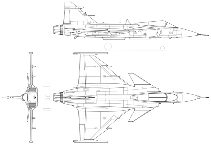
I use the specs of the legacy Saab Gripen “L” as a reference and those of the new generation “NG” as the threshold:

Lenght: 14,1m / 15,2m
Span: 8,4m / 8,6m
Wing Area: 25,5m² / 31m²
Empty Weight: 6600kg / 7600kg
Fuel Capacity: 2800l (2300kg) / 4200l (3400kg)

It is reasonable to assume internal weapon bays and complex serpentine air intake ducting will decrease fuselage volume available for fuel, while increasing the empty weight (in comparison to a traditional design). Consequently, I assume an empty weight more towards the NG (7600kg), while considering a fuel tank capacity more in the region of the L (2300kg), to keep the fuselage volume within reasonable margins (cross section / length).
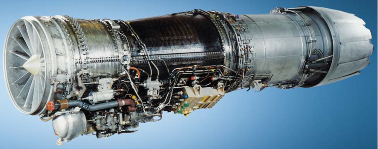
I think that's reasonable assumptions to start with. However, modern production technologies may allow the weight growth to be smaller. How much fuel tank volume is indeed achievable will be seen in the end of the design process... In any case it's quite clear that the desired LMF must use the GE F414 engine, as installed in the NG.

What's next?

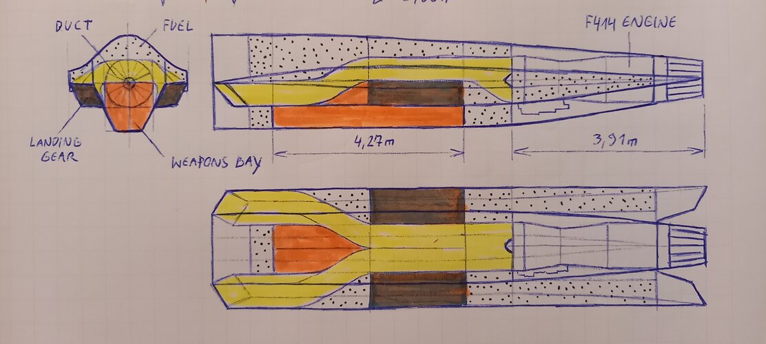
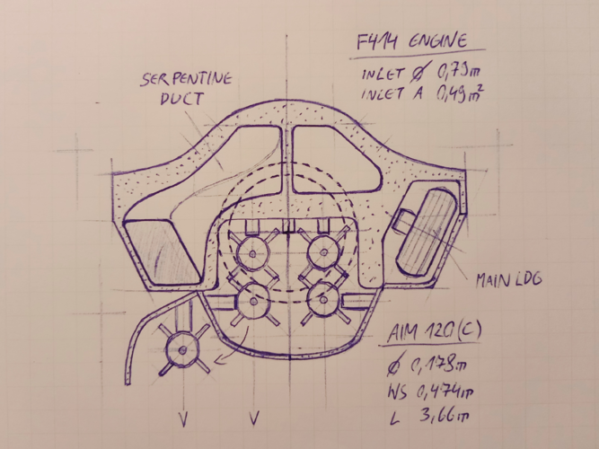
To get an idea of the internal volume required I decided to start with a fuselage cross section drawing. It is basically determined by three items (*four):

1) the engine diameter
2) the weapons bay
3) the engine air intake ducting
...AND not to forget 4) the main landing gear!*

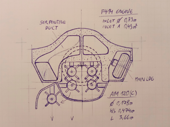
ad 1): The F414 engine's intake diameter is given with 0,79m, maximum diameter 0,89m. Not to forget the accessories attached to the bottom of the engine require some space as well. The length of the engine is given with 3,91m.

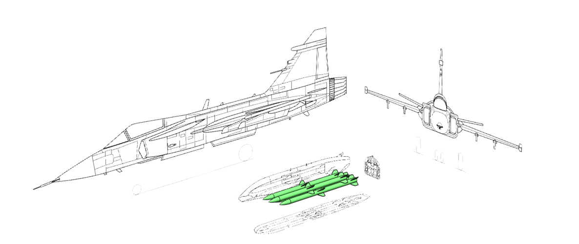
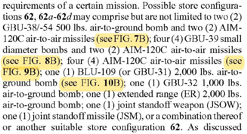
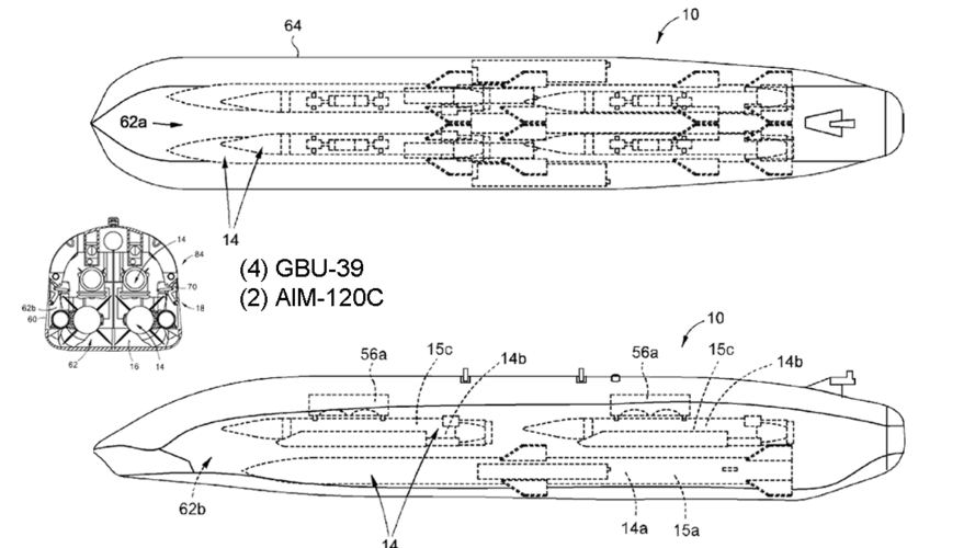
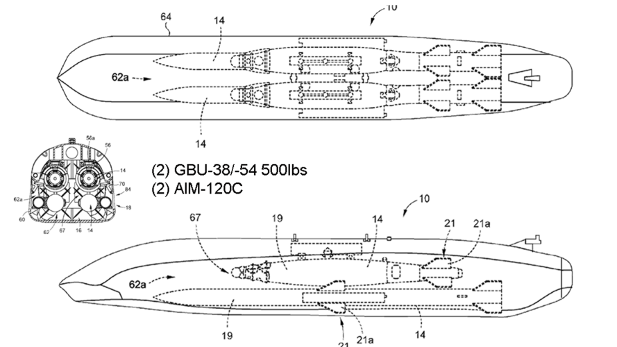
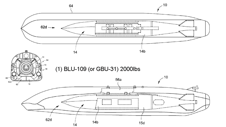
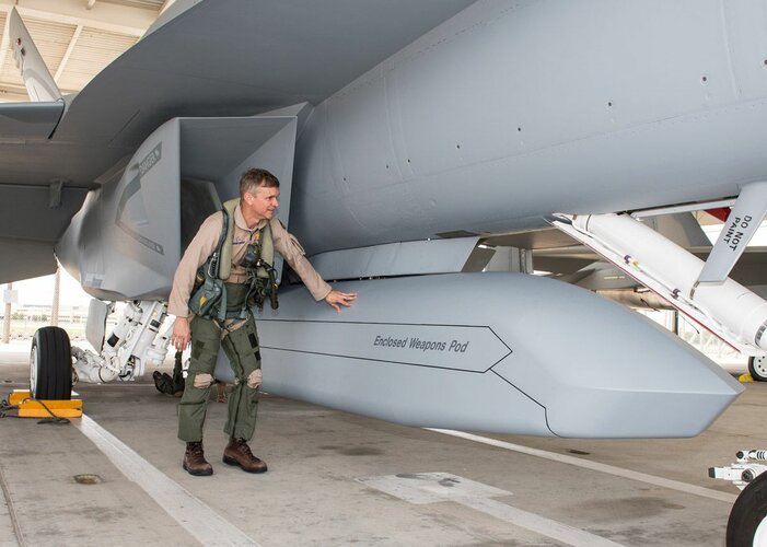
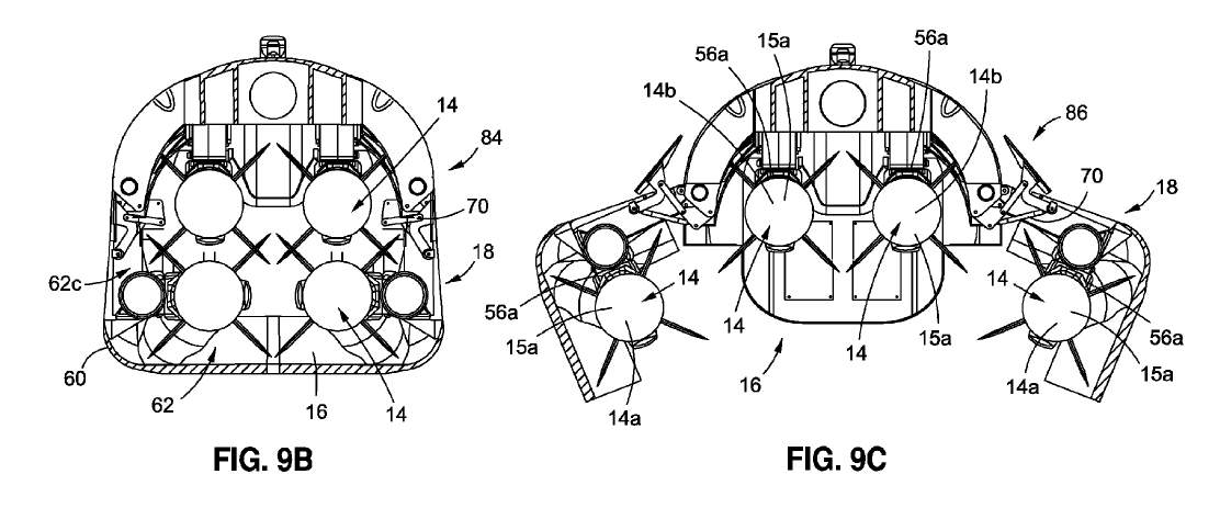
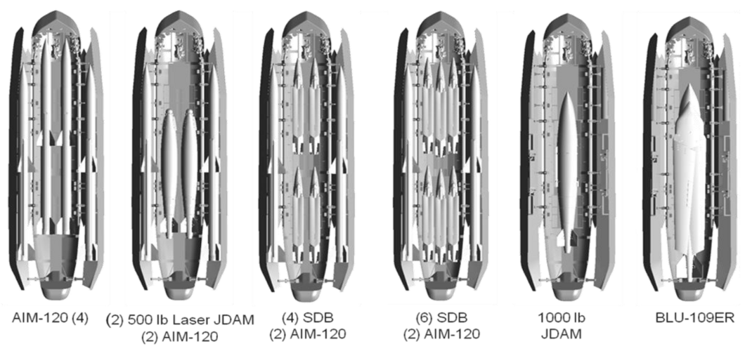
ad 2): After some initial sketching of fuselage cross sections Boeing's Enclosed Weapons Pod (EWP) came to my mind... It accepts four AIM-120 (C) and is actually a quite compact and versatile package. Luckily a patent including detailed line drawings is available. I decided to use the EWP as a baseline to size the internal weapons bay of my LMF concept.
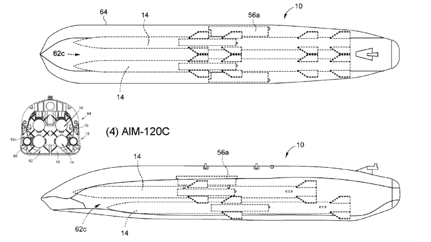
AIM-120C:
Length: 3,66m
Diameter: 0,178m
Wingspan: 0,474m

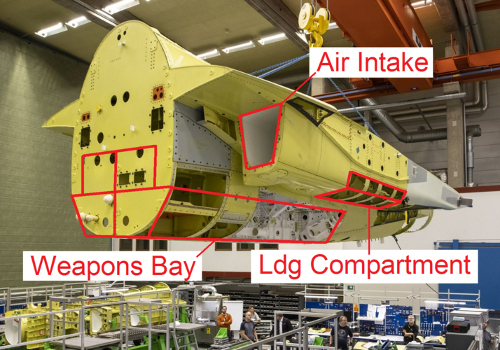
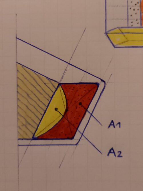
ad 3): The F414's intake diameter results in an intake area of 0,49m². Obviously one or two air ducts with a continuous duct cross section must be routed through the fuselage from the intake(s) to the engine's mouth. Serpentine ducts are mainly a geometrical challenge. I came to the conclusion that routing it on top of the weapons bay is most likely the best solution. However, the question what kind of air intake will be used remains open at this stage. A dorsal inlet was ruled out from the onset. It would be the best solution to avoid a long serpentine duct penetrating the fuselage, but I consider it as not applicable due to the lack of practical examples (in highly manoeuvrable supersonic fighter jets).

ad 4): To be honest, I forgot to account for main landing gear compartments in my first considerations :) Actually a quite important item and not easy to integrate in addition to the weapons bay and serpentine ducts (without making the aircraft fat).
Since I've already decided to use a central single "EWP-style bay" a centralized landing gear compartment is not applicable (e.g. F-16). Furthermore, Boeing's EWP features doors that swing to the sides. That prohibits the use of side intakes that go all the way to the bottom of the fuselage (e.g. F-22).
Ultimately I came to the conclusion that it is most efficient to hide the main landing gear behind trapezoid side intakes. Kind of a “stealthified” version of Tornado or Jaguar intakes. The long serpentine duct going all the way through the fuselage required by chin intakes made me decide against it. I also wanted to avoid the landing gear to retract into the wing, which would result in extra-long landing gear legs (e.g. X-32).

The attached sketch illustrates the basic concept I’ll use. Actually the cross section of Boeing’s T-7A Red Hawk is very similar ;) To be continued...
 

Attachments

  • Saab_JAS_39_Gripen_3-view.svg.png
    Saab_JAS_39_Gripen_3-view.svg.png
    121.7 KB · Views: 437
  • ec69b24b6b8531c5ccab5ed2a263ae45.jpg
    ec69b24b6b8531c5ccab5ed2a263ae45.jpg
    115.5 KB · Views: 358
  • Boeing EWP_5.PNG
    Boeing EWP_5.PNG
    69.3 KB · Views: 349
  • Boeing EWP_1.PNG
    Boeing EWP_1.PNG
    110.9 KB · Views: 324
  • GE_F414_001.PNG
    GE_F414_001.PNG
    1.9 MB · Views: 334
  • 20211228_140219.png
    20211228_140219.png
    6 MB · Views: 403
  • Boeing EWP_12.PNG
    Boeing EWP_12.PNG
    586.5 KB · Views: 441
Last edited:
Here is two screenshots of the weapons bay I’ve designed for the LMF. As mentioned in my previous post, the layout is based on Boeing’s EWP and can accommodate the same amount of ordnance. The rest of the fuselage will be designed around this bay.

Internal dimensions:
Length: 4,27m
With: 0,82m
Height: 0,615
Volume: 2,78m³
 

Attachments

  • LMF_wb_003.PNG
    LMF_wb_003.PNG
    1.1 MB · Views: 375
  • LMF_wb_004.PNG
    LMF_wb_004.PNG
    1,008.3 KB · Views: 394
Last edited:
For comparison an EWP attached to the belly of a Gripen "L"...
 

Attachments

  • Boeing EWP_22.png
    Boeing EWP_22.png
    52.9 KB · Views: 401
  • Boeing EWP_21.png
    Boeing EWP_21.png
    85.7 KB · Views: 380
  • Boeing EWP_23.png
    Boeing EWP_23.png
    119 KB · Views: 364
One question: is this a multirole fighter, or just A2A oriented?
 
In terms of general layout, side intakes like this:

astovl-force-wind-tunnel-model-jpg.168247


mcdonnell-douglas-chuck-wood-art-2-jpg.554982


Or for chin intake:

11781817_10204522972502329_1336745467919762747_n-jpg.537514
 
Last edited:
As already indicated in my first post I’ll use the T-7A as a geometrical reference. Mainly because it is powered by a F404 engine and has a cross section that represents to a great extend what I have in mind – See the pic attached. Obviously it is designed as a trainer. Hence, it is smaller and lighter as the envisaged LMF and does not have basic stealth features like edge alignment.
 

Attachments

  • Boeing_T-7A_002.png
    Boeing_T-7A_002.png
    2.2 MB · Views: 343
  • 20211228_140219_small.png
    20211228_140219_small.png
    3 MB · Views: 324
As the thread title “Lightweight Multirole Fighter (LMF)” suggests
Ups, sorry!

In that case, wouldn't the bay need to be bigger? Or are you considering just weapons of SDB type?
Of course bigger would be better, but it would eat up too much fuselage volume. It is a small aircraft, where should all the fuel go?! However, Boeing's EWP can accommodate various ordnance. I think it's a pretty smart concept. See the attached...
 

Attachments

  • Boeing EWP_10.PNG
    Boeing EWP_10.PNG
    50.2 KB · Views: 280
  • Boeing EWP_1.PNG
    Boeing EWP_1.PNG
    110.9 KB · Views: 258
  • Boeing EWP_2.PNG
    Boeing EWP_2.PNG
    336.1 KB · Views: 249
  • Boeing EWP_3.PNG
    Boeing EWP_3.PNG
    332.8 KB · Views: 246
  • Boeing EWP_4.PNG
    Boeing EWP_4.PNG
    227.6 KB · Views: 271
for that northrop single engined design.. was there ever pics of the bay unveiled?

On a related design note, I always liked this fan art of a miniature YF-23
but I feel that two small bays that are the size of 2 AAMs, are less useful than 1 regular sized bay
1640740990481.jpeg

I also have always wanted to see a light fighter design based on the X-36. the bottom is flat and wide enough that it looks like it could accommodate a single bay between the wheel bays
john-wrbanek-x-36-18a.jpg


Finally there's the X-2 demonstrator from Mitsubishi.
Its roughly Gripen sized with similar thrust. Currently it doesnt look wide enough to incorporate any meaningful bay size
but how much could be modified to accomodate one?

046cbcca-0845-11e6-a623-b84d06a39ec2
 
The attached sketch illustrates the basic concept I’ll use. Actually the cross section of Boeing’s T-7A Red Hawk is very similar
Maybe also look at the F-8A Crusader for inspiration? (In terms of internal arrangement)

Large internal volume (4,800L fuel, guns and the rocket pack) and weighed only 8t despite the very heavy J57 engine. Replace the chin intake with side intakes, allowing you to move the nose gear forward to extend the internal bay and that might give you something to work with.
 
How about configuring it slightly asymmetrically?
My comment is inspired by Burt Rutan's ARES light-weight, ground-attack proof-of-concept.

Can you get by with a single engine inlet mounted on one side of the fuselage?

Internal airflow does not have to be perfectly symmetrical as long as it meets the compressor face at a reasonable angle.
Offsetting the intake trunk to one side would simplify fuselage internal design.

You could keep the bomb-bay almost on the center-line. It should be able to perform its primary mission with internal fuel and internal bombs and missiles. One large bomb-bay is easier to re-configure for weapons invented later.
If the internal 20 mm cannon is mounted on the opposite side, you do not need to worry about muzzle blast messing with engine intake air. I assumed an internal cannon because many Third World customers will struggle to afford missiles that cost hundreds of thousands of dollars each.

The main wheel on the intake side could retract aft into the space where the inlet trunk turns to meet the compressor face.
You may want to mount the nose-wheel slightly off-center to clear the bomb-bay.

Otherwise make it look like Aldo Spandoni minus the tail feathers. I would favor a diamond or delta wing planform.
Paddles - mounted on the engine tail-pipe - can substitute for tail feathers.
 
The attached sketch illustrates the basic concept I’ll use. Actually the cross section of Boeing’s T-7A Red Hawk is very similar
Maybe also look at the F-8A Crusader for inspiration? (In terms of internal arrangement)

Large internal volume (4,800L fuel, guns and the rocket pack) and weighed only 8t despite the very heavy J57 engine. Replace the chin intake with side intakes, allowing you to move the nose gear forward to extend the internal bay and that might give you something to work with.

I always liked the simple fuselage design of the F-8 (and A-7)! The challenge is to find sufficient space for weapons and main landing gears close to the center of gravity of the aircraft. A small single engine aircraft makes this even harder. I don't think it is feasible to place the weapons bay in front of the main landing gear compartment without running into CoG issues.
 
Last edited:
As already indicated in my first post I’ll use the T-7A as a geometrical reference. Mainly because it is powered by a F404 engine and has a cross section that represents to a great extend what I have in mind – See the pic attached. Obviously it is designed as a trainer. Hence, it is smaller and lighter as the envisaged LMF and does not have basic stealth features like edge alignment.
The attached sketch shows the general arrangement of the 4 main items a little bit better. The drawing is not up to scale, but is not too far off I think.
Note: If a 14m long aircraft is assumed the combined length of engine and bay consume approximately 60% of overall length!
 

Attachments

  • 20211229_120131.jpg
    20211229_120131.jpg
    1.4 MB · Views: 348
As already indicated in my first post I’ll use the T-7A as a geometrical reference. Mainly because it is powered by a F404 engine and has a cross section that represents to a great extend what I have in mind – See the pic attached. Obviously it is designed as a trainer. Hence, it is smaller and lighter as the envisaged LMF and does not have basic stealth features like edge alignment.
The attached sketch shows the general arrangement of the 4 main items a little bit better. The drawing is not up to scale, but is not too far off I think.
Note: If a 14m long aircraft is assumed the combined length of engine and bay consume approximately 60% of overall length!
Excicing(
 
Before I start the detailed design in CAD I got a few general questions about air intakes and the associated duct(s) I hope some knowledgeable members can answer. Obviously I can't design a supersonic fighter in detail, but I wanna make sure it is a feasible design on a conceptual level. ;)

1) Shall I size the area of the air intake equal to the area of the engine's intake area? (0,49 m² in case of the F414).
2) What is a representative number for the wall thickness of the duct? e.g. 10 mm?
3) Is a DSI air inlet suitable for a parallelogram-shaped intake opening? I'm asking because the F-35's is a trapezoid (symmetrical).
4) If yes, is the inlet bump asymmetrical? (see sketch).
5) What would be considered as the intake area? The whole parallelogram (A1 + A2) or only the red area (without bump)?
 

Attachments

  • 20211229_144727.jpg
    20211229_144727.jpg
    615.6 KB · Views: 380
I always liked the simple fuselage design of the F-8 (and A-7)! The challenge is to find sufficient space for weapons and main landing gears close to the center of gravity of the aircraft. A small single engine aircraft makes this even harder. I don't think it is feasible to place the weapons bay in front of the main landing gear compartment without running into CoG issues.
I think the Center of Gravity issues would be manageable. If you look at the F-8A below, the combined weight of the expendable rockets, Sidewinders and 20mm ammo is 1,250lbs, all located slightly forward of the wing. Not counting the fixed weight of pylons (200lbs), guns and rocket launcher mechanism. So a 2,000lb internal payload in the same location doesn’t seem unreasonable.

Might still be difficult because the Crusader has that heavy J57 engine in the back keeping the weights in balance, so a lighter F414 might cause the CoG to move forward.

The solution could be a rearward retracting landing gear into the fuselage, allowing the weapons bay to be moved back to a location right beneath the wing. Is that an option? Trying to think of a fighter design that has that…
 

Attachments

  • D87596D5-85D2-4812-9133-9E7744E4C40A.jpeg
    D87596D5-85D2-4812-9133-9E7744E4C40A.jpeg
    343.3 KB · Views: 399
Last edited:
Of course bigger would be better, but it would eat up too much fuselage volume. It is a small aircraft, where should all the fuel go?! However, Boeing's EWP can accommodate various ordnance. I think it's a pretty smart concept. See the attached...
I see, thanks

I know you said this was about designing and not so much about questioning, so please don't take offence at my comments below:

1. A multirole fighter with bays big enough for serious ordnance has the size of the LTS. I tried the same exercise and the result was an almost identical layout to LTS, but the reality turned even a bit bigger than I conceived (my plane was already clearly bigger than a F-16). The LTS is at the very lowest size range that allows for meaningful capability, bigger and a single engine of its size class would not be enough (see F-35), which greatly defeats the purpose of the single engine plane as 'lo' element of the mix. Saab FS2020 was the 5th gen Gripen and it was 17 m long, 10 t empty, so almost identical to LTS.

2. If you develop further your layout you come again to something very close to LTS. Engine goes a bit upward to clear the bays, while the side intakes produce no benefit in this particular situation. The air ducts from the two intakes need to converge in front of the engine in a smooth way, so the bay either is placed on a lower plane, or goes so much to the front that it is incompatible with a light plane. If the bay goes to a lower plane re. the engine, the development of the fuselage is vertical and therefore it does not make sense to place the intakes at the sides, which is BTW a heavier and draggier alternative itself, compared to one ventral intake. The nose and cockpit in front of the engine, the intake in front of the bay is the most optimal placement of elements

3. MiG proposed some light 5th gen fighters at MAKS21, maybe they have some useful ideas? But it was not clear to me what they were up to in terms of bay space and propulsion capabilities. I think your idea of the externally carried weapons storage is what would make this size of fighter feasible, obviously the drag of the whole assembly may make it problematic for supersonic flight, but maybe this combined with semiconformal carriage of AAMs (not to burden the aircraft with the external storage in A2A missions) may be a viable way of getting a multirole 5th gen fighter which is light in the traditional sense of the word
 
Last edited:
Before I start the detailed design in CAD I got a few general questions about air intakes and the associated duct(s) I hope some knowledgeable members can answer. Obviously I can't design a supersonic fighter in detail, but I wanna make sure it is a feasible design on a conceptual level. ;)

1) Shall I size the area of the air intake equal to the area of the engine's intake area? (0,49 m² in case of the F414).
2) What is a representative number for the wall thickness of the duct? e.g. 10 mm?
3) Is a DSI air inlet suitable for a parallelogram-shaped intake opening? I'm asking because the F-35's is a trapezoid (symmetrical).
4) If yes, is the inlet bump asymmetrical? (see sketch).
5) What would be considered as the intake area? The whole parallelogram (A1 + A2) or only the red area (without bump)?
1. No. Air is ingested at the inlet, slowdown and then only fed into the engine. The goal is to convert ram air pressure with static pressure (as air slow down, Pressure rises - remember Bernouilli (not a pasta brand!)). So, not only capture area is a bit smaller than engine inlet surface, but then cross section is increased on a certain ratio to change the speed of the airflow from the speed of the aircraft to something much slower (Mach 0.3, 0.5). The ratio b/w inlet capture area and the largest duct area depends of the altitude and design speed of the fighter. Use something as big as 1.5 to be realistic with a duct length of 5 or 6 the diameter
The freestream Mach number was 0.27. The s-duct had a
centerline offset of / = 0.5, an area ratio of / = 1.52, and length
/ = 4.95.
If you are wondering, 5 is Loockheedish and 6, Dassaulliant (as I remember it).
See enclosed file if I don't forget it(!)

2. Duct Thickness is1 to 2 mmm depending of material (metals/CFRP). But the most important dimension is for the structure (hoop stress). Use 2 inches.

3. DSI are just mouse/cone like inlets that are static. As a good approximate just copy F-104 or Mirages

4. Assymetrical (think AoA)

5. Capture area is the effective geometrical surface through where air can be fed into the engine (see pg 42 of document).
 

Attachments

  • JacobABrandon_MastersThesis_2020.pdf
    4.3 MB · Views: 157
Of course bigger would be better, but it would eat up too much fuselage volume. It is a small aircraft, where should all the fuel go?! However, Boeing's EWP can accommodate various ordnance. I think it's a pretty smart concept. See the attached...
I see, thanks

I know you said this was about designing and not so much about questioning, so please don't take offence at my comments below:

1. A multirole fighter with bays big enough for serious ordnance has the size of the LTS. I tried the same exercise and the result was an almost identical layout to LTS, but the reality turned even a bit bigger than I conceived (my plane was already clearly bigger than a F-16). The LTS is at the very lowest size range that allows for meaningful capability, bigger and a single engine of its size class would not be enough (see F-35), which greatly defeats the purpose of the single engine plane as 'lo' element of the mix. Saab FS2020 was the 5th gen Gripen and it was 17 m long, 10 t empty, so almost identical to LTS.

2. If you develop further your layout you come again to something very close to LTS. Engine goes a bit upward to clear the bays, while the side intakes produce no benefit in this particular situation. The air ducts from the two intakes need to converge in front of the engine in a smooth way, so the bay either is placed on a lower plane, or goes so much to the front that it is incompatible with a light plane. If the bay goes to a lower plane re. the engine, the development of the fuselage is vertical and therefore it does not make sense to place the intakes at the sides, which is BTW a heavier and draggier alternative itself, compared to one ventral intake. The nose and cockpit in front of the engine, the intake in front of the bay is the most optimal placement of elements

3. MiG proposed some light 5th gen fighters at MAKS21, maybe they have some useful ideas? But it was not clear to me what they were up to in terms of bay space and propulsion capabilities. I think your idea of the externally carried weapons storage is what would make this size of fighter feasible, obviously the drag of the whole assembly may make it problematic for supersonic flight, but maybe this combined with semiconformal carriage of AAMs (not to burden the aircraft with the external storage in A2A missions) may be a viable way of getting a multirole 5th gen fighter which is light in the traditional sense of the word

It's just like the interceptors of the 1950's putting early AAMs into an internal bay. there is no workaround: a missile bay of meaningful size inevitably impacts... the aircraft around it.
Extreme case: the Avro Arrow. A missile bay the size of a Lancaster / B-29 (!) just to put a handful of Sparrows (four of them !)
 
The attached sketch shows the general arrangement of the 4 main items a little bit better. The drawing is not up to scale, but is not too far off I think.
Note: If a 14m long aircraft is assumed the combined length of engine and bay consume approximately 60% of overall length!
Thanks for writing this thread, and capturing your ideas.

Have you thought about how the weapon bay will be loaded for this configuration? I would think it difficult to not clash with the main gear because the doors on this style of bay sweep through a large angle. Your main gear basically has to swing out sideways before rotating downwards which is challenging for both the mechanism and clearances to other items e.g. the wing. Undercarriage is annoying.

I think you're overconstraining yourself in your problem. I'd focus on mass as the target rather than physical size. Empty mass is most closely related to cost. Any physical size constraints are driven by infrastructure e.g. hangars but most of these are really quite big nowadays
 
How about folding the fins on missiles that are stowed internally?
 
1. A multirole fighter with bays big enough for serious ordnance has the size of the LTS. I tried the same exercise and the result was an almost identical layout to LTS, but the reality turned even a bit bigger than I conceived (my plane was already clearly bigger than a F-16). The LTS is at the very lowest size range that allows for meaningful capability, bigger and a single engine of its size class would not be enough (see F-35), which greatly defeats the purpose of the single engine plane as 'lo' element of the mix. Saab FS2020 was the 5th gen Gripen and it was 17 m long, 10 t empty, so almost identical to LTS.
Meaningful capability is the key word here. One would argue that four AMRAAMs is quite a meaningful load! How I perceive this thread is we are trying to design a small (and thus lowish) cost stealth fighter.

The Gripen link to me indicates we focus on a defensive mission where the fighter inventory serves as a defensive deterrent rather than a offensive one. For such a role four AMRAAMs and LO/VLO airframe should suffice just fine! F-35 is much bigger than Gripen and it can only carry 6 AMRAAMs intrnally. More fuel yes, but this is where I refer back to the intended role of the aircraft. In place of the missiles I'm sure one large or two smaller LGB's or other guided weapons could be fitted too if required...

My apologies if I have "read" the requirements of the aircraft being conceived wrong, but I think there is certainly a place for such an low end stealth fighter. It will obviously not compete with larger types but it will certainly serve a useful purpose to a nation where protection of local airspace is priority over limited offensive capability. Looking at you Switzerland! And like F-35, once stealth was used to obtain air superiority we can hang bigger stuff on the wings too in an offensive scenario.

Following with interest!
 
TomcatViP has mostly stolen my thunder, but here goes anyway :)

2) What is a representative number for the wall thickness of the duct? e.g. 10 mm?

Purely based on intuition that sounds like rather a lot, I'd expect more like 1 to 5mm with frame stiffeners on the outside, if metallic. Composite might be thicker (and lack stiffeners), but 10mm still seems generous.

3) Is a DSI air inlet suitable for a parallelogram-shaped intake opening? I'm asking because the F-35's is a trapezoid (symmetrical).
4) If yes, is the inlet bump asymmetrical? (see sketch).

A DSI intake is basically a fixed conical shock intake, not unlike the F-104 inlet. To minimize spillage (compressing more air across the shock than ducted to the engine, for an excess drag penalty) the cowl should provide an approximately shock-on-lip condition at the design point. This would seem to favour an arc-like shape, but that could be ruled out by edge alignment considerations for stealth - though the EMD F-23 had an interesting solution.

FWIW, the J-20 went from a design similar to the one in your sketch to a trapezoid shape like the F-35, i.e. it evolved into something better approximating an arc in the final configuration. Both these aircraft have asymmetrical bumps because the "virtual cone" in the streamline-traced flow field used to derive the bump surface is set at a non-zero angle of attack. It's possible that you could use this to bias the flow field a bit so that a parallelogram aperture works, but the J-20 apparently ditched that approach, as mentioned.

1) Shall I size the area of the air intake equal to the area of the engine's intake area? (0,49 m² in case of the F414).
5) What would be considered as the intake area? The whole parallelogram (A1 + A2) or only the red area (without bump)?

Depends on what you want to do with the figure. The red area could very roughly correspond to throat area, but with a DSI bump the air may not be flowing through this cross section parallel to the page normal. In any case, the aim is to diffuse the subsonic air flow downstream of the throat such that it arrives at the engine face at Mach <0.6 AFAIK. IIRC that figure was an upper bound, because it applied to podded airliner engines with low L/D ducts (short + large diameter). Incidentally, I can see a potential problem in this regard (large diffusor angle) in your beam view drawing - the duct expands very rapidly aft of the weapons bay to meet the engine fan. That might be too aggressive and invite flow separation.
 
Last edited:
It might be a controversial decision but what about going with MICA as the AA missile? Adequate range but a fair bit smaller and lighter.

I was thinking the same - though for internal carriage Mica may not be very volume efficient because with its long chord strakes it staggers poorly. But it is something to consider!
 
Might still be difficult because the Crusader has that heavy J57 engine in the back keeping the weights in balance, so a lighter F414 might cause the CoG to move forward.

Engines of the era often had long jet pipes which put the mass relatively far forward in the airframe, though - that could mitigate the issue somewhat.
 
1. A multirole fighter with bays big enough for serious ordnance has the size of the LTS. I tried the same exercise and the result was an almost identical layout to LTS, but the reality turned even a bit bigger than I conceived (my plane was already clearly bigger than a F-16). The LTS is at the very lowest size range that allows for meaningful capability, bigger and a single engine of its size class would not be enough (see F-35), which greatly defeats the purpose of the single engine plane as 'lo' element of the mix. Saab FS2020 was the 5th gen Gripen and it was 17 m long, 10 t empty, so almost identical to LTS.
Meaningful capability is the key word here. One would argue that four AMRAAMs is quite a meaningful load! How I perceive this thread is we are trying to design a small (and thus lowish) cost stealth fighter.

The Gripen link to me indicates we focus on a defensive mission where the fighter inventory serves as a defensive deterrent rather than a offensive one. For such a role four AMRAAMs and LO/VLO airframe should suffice just fine! F-35 is much bigger than Gripen and it can only carry 6 AMRAAMs intrnally. More fuel yes, but this is where I refer back to the intended role of the aircraft. In place of the missiles I'm sure one large or two smaller LGB's or other guided weapons could be fitted too if required...

My apologies if I have "read" the requirements of the aircraft being conceived wrong, but I think there is certainly a place for such an low end stealth fighter. It will obviously not compete with larger types but it will certainly serve a useful purpose to a nation where protection of local airspace is priority over limited offensive capability. Looking at you Switzerland! And like F-35, once stealth was used to obtain air superiority we can hang bigger stuff on the wings too in an offensive scenario.

Following with interest!
Exactly my thoughts!
 
Of course bigger would be better, but it would eat up too much fuselage volume. It is a small aircraft, where should all the fuel go?! However, Boeing's EWP can accommodate various ordnance. I think it's a pretty smart concept. See the attached...
I see, thanks

I know you said this was about designing and not so much about questioning, so please don't take offence at my comments below:

1. A multirole fighter with bays big enough for serious ordnance has the size of the LTS. I tried the same exercise and the result was an almost identical layout to LTS, but the reality turned even a bit bigger than I conceived (my plane was already clearly bigger than a F-16). The LTS is at the very lowest size range that allows for meaningful capability, bigger and a single engine of its size class would not be enough (see F-35), which greatly defeats the purpose of the single engine plane as 'lo' element of the mix. Saab FS2020 was the 5th gen Gripen and it was 17 m long, 10 t empty, so almost identical to LTS.

2. If you develop further your layout you come again to something very close to LTS. Engine goes a bit upward to clear the bays, while the side intakes produce no benefit in this particular situation. The air ducts from the two intakes need to converge in front of the engine in a smooth way, so the bay either is placed on a lower plane, or goes so much to the front that it is incompatible with a light plane. If the bay goes to a lower plane re. the engine, the development of the fuselage is vertical and therefore it does not make sense to place the intakes at the sides, which is BTW a heavier and draggier alternative itself, compared to one ventral intake. The nose and cockpit in front of the engine, the intake in front of the bay is the most optimal placement of elements

3. MiG proposed some light 5th gen fighters at MAKS21, maybe they have some useful ideas? But it was not clear to me what they were up to in terms of bay space and propulsion capabilities. I think your idea of the externally carried weapons storage is what would make this size of fighter feasible, obviously the drag of the whole assembly may make it problematic for supersonic flight, but maybe this combined with semiconformal carriage of AAMs (not to burden the aircraft with the external storage in A2A missions) may be a viable way of getting a multirole 5th gen fighter which is light in the traditional sense of the word
I don't want this to degenerate into another discussion about LTS or F-35.

I just say this:
LTS is a superb design concept, neat looking and I hope it will be produced in great numbers once development is concluded. I do accept your personal opinion, but I disagree.

Best regards, Michael

EDIT:
"...I tried the same exercise and the result was an almost identical layout to LTS, but the reality turned even a bit bigger than I conceived (my plane was already clearly bigger than a F-16)..."

You could start a new thread and share the details of your design. I think a lot of people would be interested in your thoughts and conclusions. Just a suggestion.
 
Last edited:
The attached sketch shows the general arrangement of the 4 main items a little bit better. The drawing is not up to scale, but is not too far off I think.
Note: If a 14m long aircraft is assumed the combined length of engine and bay consume approximately 60% of overall length!
Thanks for writing this thread, and capturing your ideas.

Have you thought about how the weapon bay will be loaded for this configuration? I would think it difficult to not clash with the main gear because the doors on this style of bay sweep through a large angle. Your main gear basically has to swing out sideways before rotating downwards which is challenging for both the mechanism and clearances to other items e.g. the wing. Undercarriage is annoying.

I think you're overconstraining yourself in your problem. I'd focus on mass as the target rather than physical size. Empty mass is most closely related to cost. Any physical size constraints are driven by infrastructure e.g. hangars but most of these are really quite big nowadays

The clearance of main gear legs and bay doors are indeed an area of concern. But I think it's not a showstopper... For instance, Gripen's landing gear is hinged in a way that the wheel rotates to the desired position in the compartment. See the attached video...

I focus on physical size because I cannot design mass in CAD. Once I've established a CAD model I hope to be able to estimate mass.

View: https://youtu.be/zvuzkEfky-g
 
I just don't see a way to have a bay the size of the Boeing external pod without losing too much internal space on a Gripen sized fighter unless it looks as fat as a modern Tunnan.

Some Northrop ideas for small fighters:

north1983fcf-4s-jpg.21273


This F-20 supercruise study embeds two AIM-120s in an external fairing

f-20-derivative-jpg.156938
 
Meaningful capability is the key word here. One would argue that four AMRAAMs is quite a meaningful load! How I perceive this thread is we are trying to design a small (and thus lowish) cost stealth fighter.

The Gripen link to me indicates we focus on a defensive mission where the fighter inventory serves as a defensive deterrent rather than a offensive one. For such a role four AMRAAMs and LO/VLO airframe should suffice just fine! F-35 is much bigger than Gripen and it can only carry 6 AMRAAMs intrnally. More fuel yes, but this is where I refer back to the intended role of the aircraft. In place of the missiles I'm sure one large or two smaller LGB's or other guided weapons could be fitted too if required...

My apologies if I have "read" the requirements of the aircraft being conceived wrong, but I think there is certainly a place for such an low end stealth fighter. It will obviously not compete with larger types but it will certainly serve a useful purpose to a nation where protection of local airspace is priority over limited offensive capability. Looking at you Switzerland! And like F-35, once stealth was used to obtain air superiority we can hang bigger stuff on the wings too in an offensive scenario.
Yeah, that is why I asked about the multirole aspect, it is (much) more difficult to fit A2G ordnance in a fighter than AAMs.

As to the low-end 5th gen fighters with reduced functionality and roles, since all weapons systems have become so expensive to buy and operate and so difficult to master, and most of the avionics needed for different roles are similar, the clear tendency is to have multirole planes with relatively high capabilities and size. Mass is not such a crucial cost driver anymore and that is IMHO why we see a substantial size creep in the 5th gen

I don't want this to degenerate into another discussion about LTS or F-35.

I do accept your personal opinion, but I disagree.
No intention to drift the discussion in that direction, just sharing some results of a very similar effort 4 years ago. I do think some of the layout thoughts I comment above apply, but of course there are many ways of doing things and I look forward to the results of your effort
 
Thanks for writing this thread, and capturing your ideas.

Have you thought about how the weapon bay will be loaded for this configuration? I would think it difficult to not clash with the main gear because the doors on this style of bay sweep through a large angle. Your main gear basically has to swing out sideways before rotating downwards which is challenging for both the mechanism and clearances to other items e.g. the wing. Undercarriage is annoying.

I think you're overconstraining yourself in your problem. I'd focus on mass as the target rather than physical size. Empty mass is most closely related to cost. Any physical size constraints are driven by infrastructure e.g. hangars but most of these are really quite big nowadays

The clearance of main gear legs and bay doors are indeed an area of concern. But I think it's not a showstopper... For instance, Gripen's landing gear is hinged in a way that the wheel rotates to the desired position in the compartment. See the attached video...

I focus on physical size because I cannot design mass in CAD. Once I've established a CAD model I hope to be able to estimate mass.

View: https://youtu.be/zvuzkEfky-g
I think the problem its not how the landing gear goes down or up. But looking at your sketch when the plane on the ground, the landing gear is in bay door's way. So the bay door cannot fully open(?) and make payload installation become harder to do.
 

Similar threads

Back
Top Bottom