Cyclogyros Aircraft

Schaufelrad is the type of propulsion (" Lifting rotor ") , and Ernst Zenzem (or Zeuzem?) is the designer .
Looking at those attached images has me thinking that if I had the health and the wealth it would be fun to make a movie just to feature that aircraft.
 
hesham said:

This concept was from the designer Vincent Wisniewski.

Hi,


Attachments

  • 10.png
    10.png
    54.5 KB · Views: 108
  • 11.png
    11.png
    43 KB · Views: 48
Last edited:
From this report,

and I think my dear Scott displayed them before,but where ?.
 

Attachments

  • 13.png
    13.png
    548.3 KB · Views: 33
  • 14.png
    14.png
    581.1 KB · Views: 33
  • 9.png
    9.png
    946.3 KB · Views: 35
The Strandgren "paddle-wheeler" was mentioned before, but here is an article about it from Popular Aviation, May 1934:
 

Attachments

  • 1709500920948.png
    1709500920948.png
    1.1 MB · Views: 27
Titan might be the one place with thick atmosphere and lighter gravity where a rover whose wheels are also propellers might work…but that’s pushing it.
 
Proof that even back in 1934, the Flettner rotor cylinders were seen by some as a bit of a joke.
I especially like the phrase: "it just goes to show that trick photography is not dead yet." They had no idea!!!

1709552573016.png
(from Popular Aviation, August 1934)
 
From this report.
 

Attachments

  • 28.png
    28.png
    385.3 KB · Views: 28
  • Development_of_a_Cyclogyro_Based_Flying.pdf
    561.4 KB · Views: 8
Hello,

Does anyone have more information on the defunct Bosch Aerospace Cyclorotor concept? I'd be interested in finding out more about it, it seems to be a very peculiar project that peaked my interest. Are there any specifications, dimensions, performance? Is there anyone that was previously involved in the project? Thank you!
 
Does anyone have more information on the defunct Bosch Aerospace Cyclorotor concept? I'd be interested in finding out more about it, it seems to be a very peculiar project that peaked my interest. Are there any specifications, dimensions, performance? Is there anyone that was previously involved in the project? Thank you!
Here is what I have. You should be able to find specs in the PDF.
 

Attachments

  • ADA370541.pdf
    1.9 MB · Views: 18
  • 6.1999-3906.fp.png
    6.1999-3906.fp.png
    106.4 KB · Views: 30
  • model.jpg
    model.jpg
    33.4 KB · Views: 26
  • img035.gif
    img035.gif
    95 KB · Views: 32
  • img034.jpg
    img034.jpg
    80.8 KB · Views: 39
  • img033.jpg
    img033.jpg
    40.1 KB · Views: 43
  • img032.jpg
    img032.jpg
    18.5 KB · Views: 39
  • img031.jpg
    img031.jpg
    80 KB · Views: 27
  • img030.jpg
    img030.jpg
    13.4 KB · Views: 30
  • 6-bladed propeller.jpg
    6-bladed propeller.jpg
    78.8 KB · Views: 30
  • 1.jpg
    1.jpg
    9.7 KB · Views: 38
Now for one to look like a paddlewheel riverboat..hey, where's Farmer Brown's combine?
 
Last edited:
I published a detailed history of Strandgren cyclogyro projects and tests in French magazine "Le Trait d'Union" 249 in January-February 2010.
I attach Strangren project drawing, and photos of tests: big installation at Lioré et Olivier Argenteuil factory, as well as the installation of Strandgren rotary wing to replace Breguet 14 wings at Saint-Cyr.
 

Attachments

  • Strandgren project (PhR).jpg
    Strandgren project (PhR).jpg
    46 KB · Views: 33
  • Strandgren test LeO Argenteuil (PhR).jpg
    Strandgren test LeO Argenteuil (PhR).jpg
    90.5 KB · Views: 28
  • Breguet 14 Strandgren - St Cyr (PhR).jpg
    Breguet 14 Strandgren - St Cyr (PhR).jpg
    35.5 KB · Views: 26
Last edited:
From, Техника - молодёжи 1935-6,

I am sure we spoke about it before,but where ?.
 

Attachments

  • 22.jpg
    22.jpg
    372.7 KB · Views: 26
From Modern Mechanix 1935/11.
 

Attachments

  • 20.png
    20.png
    1.7 MB · Views: 27
From Modern Mechanix 1935/11.
I have no knowledge of airplanes using cycloidal propellers, but boats have been using them for multiple decades.
I wonder if the very different densities of air and water make a difference in whether use of them is/will be successful?


Foss Launch & Tug Co., Seattle, Wash., announced it has received approval from the Dillingham Corporation, its parent company, to purchase three new, revolutionary Tractor Tugs, with an option for a fourth, as additions to its West Coast fleet. The new tugs will incorporate the Voith Schneider cycloidal propeller system developed in Germany.
...
The conceptual design of the new Foss Tractor Tugs was developed by Don Hogue, manager of administration-Ocean Division, and Jim Cole, assistant manager- Foss Shipyard. L.R. Glosten & Associates are the naval architects for the tugs. A builder has yet to be named. Foss expects to take delivery of the tugs in 1982.
 
Hi,

also a paddle wheels airplane.


From Modern Mechanix 1936/2.
 

Attachments

  • 22.jpg
    22.jpg
    105.7 KB · Views: 19
From, Техника - молодежи 1938/11,

also it's just idea,not a real projects.
 

Attachments

  • 24.png
    24.png
    1.8 MB · Views: 14
  • 25.png
    25.png
    2.7 MB · Views: 13
The latest in cyclogyro aircraft using a variant of the Magnus effect, is the Cyclotech Blackbird (an Austrian company) who has test flown their demonstrator model now.


BlackBird-demonstrator-1030x687.jpg


They intend to develop this into a flying car that would go on sale by 2035.

XhifZGArgGvReT5r5kuBpM-1200-80.jpg


Unlike the early rotor aircraft where the drums were solely for lift, Cyclotech's version uses variable pitch blades on the rotors that spin at a constant rate to maneuver the aircraft. They're currently claiming a 100 km range (this vehicle is all-electric) at up to 150 kph.
 
From Technika Lotnicza 1954,

that's almost from WSK ?.
 

Attachments

  • 5.png
    5.png
    96.4 KB · Views: 12
Related to that 1998 research by Bosch Aerospace on behalf of the NAWC:
FINAL REPORT
"CYCLOIDAL PROPULSION FOR UAV VTOL APPLICATIONS"
FOR SBIR TOPIC NUMBER N98-022

Excerpt:
BOSCH Aerospace, Inc., (BOSCH Aerospace) and subcontractor MSU RASPET Flight Research Laboratory (RASPET) accomplished successful development and testing of a prototype Curtate Cycloidal Propeller during the SBIR Phase I effort which concluded on October 31, 1998. This propulsion concept holds significant promise for adaptation to UAV VTOL operations. Thrust levels demonstrated were substantially higher than achievable by the best screw-type propellers, and approximately equal to those of high-end helicopters. Vectoring of thrust through a 360° arc, and low-noise characteristics throughout the RPM range were demonstrated. Also accomplished was identification of efficiency gain techniques that may increase the overall thrust by approximately 30%.

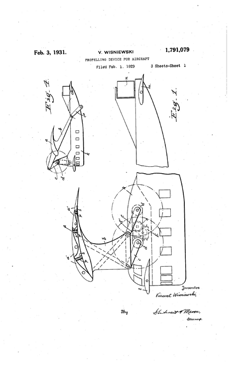
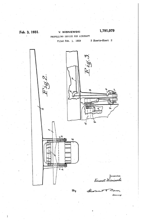
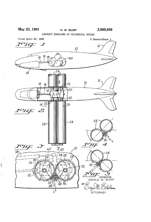
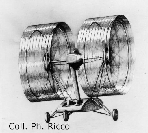
A literature search and study of cycloidal propeller testing conducted by Boeing Corporation and U.S. Government agencies between 1920 and 1945 were essential elements of Phase I. A computer model based upon this historical data was developed to allow aerodynamic performance assessment of candidate designs. The model was incorporated into the System Engineering effort where potential designs for the Navy UAV VTOL requirements were examined, and the optimum design identified. The Curtate Cycloid design provides the best hover performance, and excellent flight performance to speeds of approximately 120 knots. The BOSCH Aerospace team selected a full-scale (four-foot diameter) design. After consulting with the Navy technical monitor, the design was optimized, materials selected, and fabrication tolerances defined.

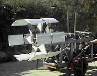
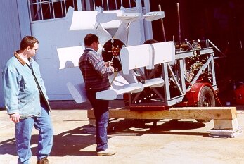
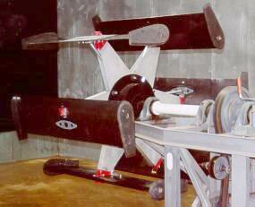
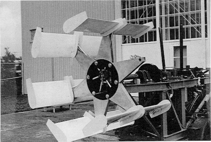
Because the Cycloidal propeller is unique, no existing test facility or test fixtures existed. Thus, we designed and fabricated a test fixture specifically suited for testing this prototype, as well as future cycloidal propeller designs. Components were function tested on CAD, then manufactured before final assembly in Huntsville. During assembly, two five-foot diameter polycarbonate (lexan) disks, which were designed to eliminate flow turbulence near the center of the blade sections, arrived late and were found to be defective. Due to time constraints, these disks were left out of the prototype. The resulting assembly was function tested, dynamically balanced, and moved to the RASPET facility for instrumentation and tests.

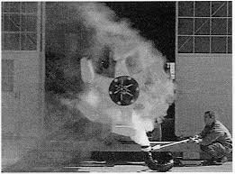
The cycloidal propeller tests were designed to accomplish two major goals, to measure thrust, and to assess thrust vector capability. Several concurrent objectives were also sought, noise assessment, educating the research team on operating characteristics of a Cycloidal propeller, examination of the prototype's mechanical performance, identification of potential design improvements, and assessment of the test fixture for future use.

Thrust measurements were taken at various RPMs in two orientations, 90° up, and then 90° down from horizontal. Vector assessment was made throughout the 360° arc. Downward thrust was approximately 20%below projections. Upward thrust in lower RPM ranges was 3% above projections. However, as RPM increased thrust decreased to the 20% below projections level. Reduced data showed that thrust varied from approximately 10.88 lb./Hp at low RPM, to 8.4 lb./Hp at high RPM. A probable solution to eliminate this anomaly was identified.
 
Last edited:

Similar threads

Back
Top Bottom