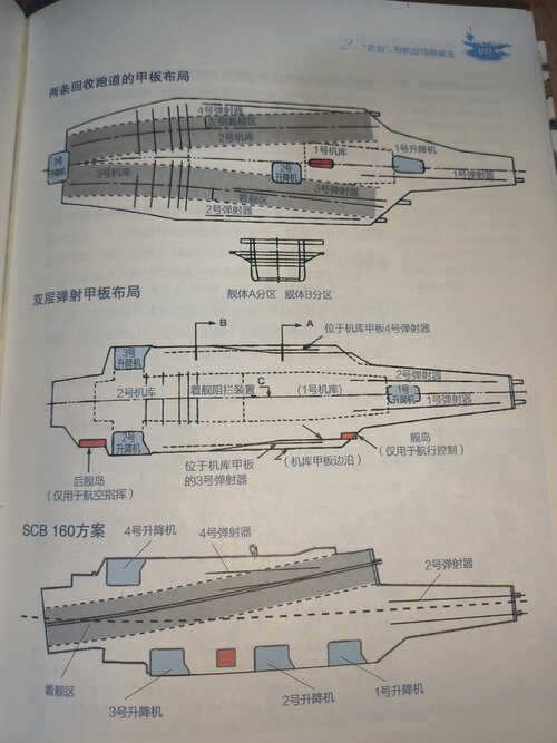
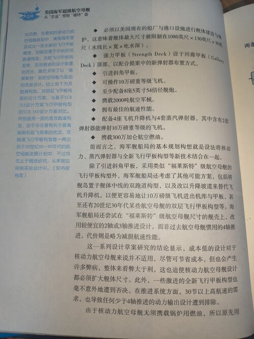
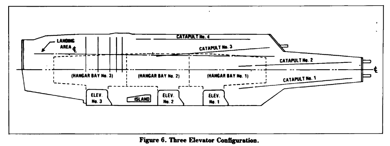
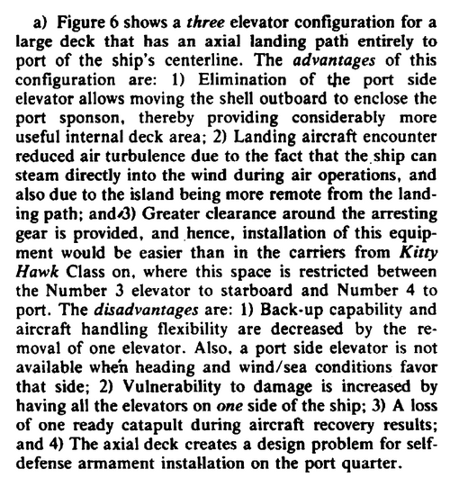
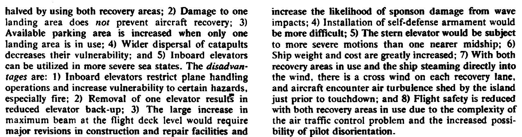
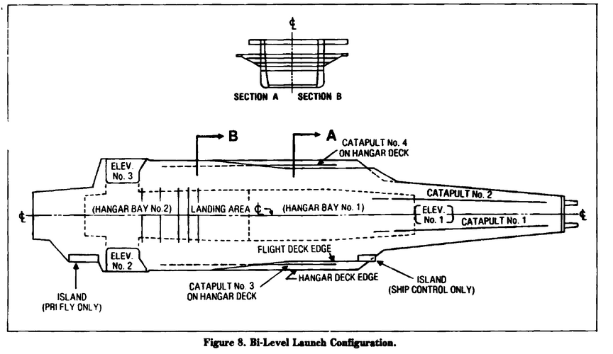
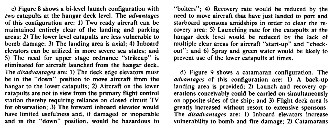
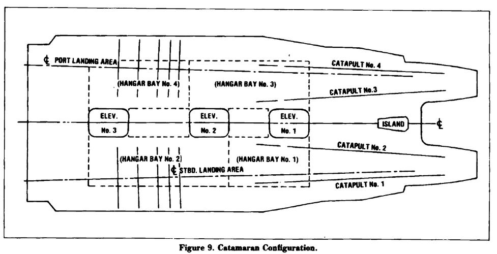
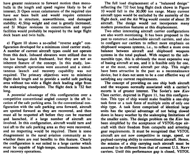
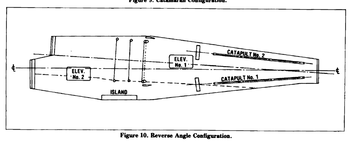
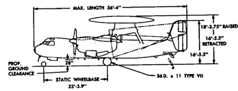
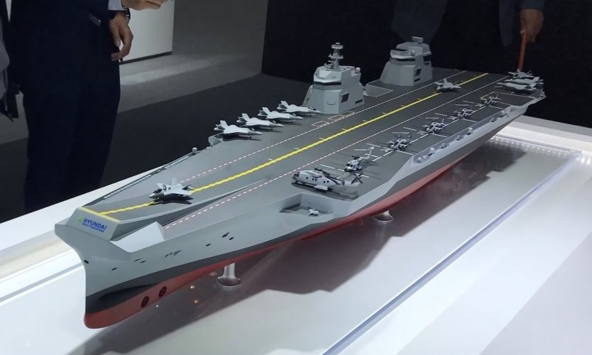
The reason I mentioned "CVN65 Enterprise" in the title is that I first came across this design plan in a Chinese book. It was discussed by the author immediately after the 1953 CVAN design plan. Based on this sequence, I initially assumed it was some kind of CVAN plan. It is also possible that I misunderstood.Moreover, the various design plans presented in this paper do not seem to have provided sources, making it hard to believe that the author proposed so many plans solely for this paper. Therefore, I think it is still worth considering where these plans might have originated when or why.
here is book
 

Attachments

  • IMG_20240604_201638.jpg
    IMG_20240604_201638.jpg
    2.6 MB · Views: 199
  • IMG_20240604_201646.jpg
    IMG_20240604_201646.jpg
    4.1 MB · Views: 164
  • IMG_20240604_201632.jpg
    IMG_20240604_201632.jpg
    3.3 MB · Views: 109
The upper design on the copied page is also from the Meier & Gale paper. The lower is SCB 160, which is indeed CVAN-65 ENTERPRISE.

It's perfectly possible that Meier & Gale did create the sketches for their paper. It would take a decent draughtsperson - which NAVSEA certainly had - about a day to come up with all of them. Added to which, that paper is summarising some of the ongoing design work their team was conducting. You wouldn't expect to see them referenced in such a case.

They might also exist in one of the three referenced documents... but maybe not. I wouldn't be bothered either way. The paper is exactly what I'd expect to see from a design team sharing their learning.
 
The upper design on the copied page is also from the Meier & Gale paper. The lower is SCB 160, which is indeed CVAN-65 ENTERPRISE.

It's perfectly possible that Meier & Gale did create the sketches for their paper. It would take a decent draughtsperson - which NAVSEA certainly had - about a day to come up with all of them. Added to which, that paper is summarising some of the ongoing design work their team was conducting. You wouldn't expect to see them referenced in such a case.

They might also exist in one of the three referenced documents... but maybe not. I wouldn't be bothered either way. The paper is exactly what I'd expect to see from a design team sharing their learning.
so actually have no link with development of CVN65. Thanks
 
Victorious was razed to the hangar deck and a rebuilt upwards. They didn't need to worry about girder strength that much, the ship was in dry dock.

But they did have to design the rebuild to take into consideration the strength of the flight deck as part of the ship's girder. The Essex class, and follow-on Midways, didn't have to do that. The US could build a much larger, redesigned flight deck, move elevators, etc., because the hanger and flight deck were superstructure, not part of the hull.
Which explains far more about the lack of rebuilds than the method of carrier construction.

It doesn't help that the British carriers were also smaller than the Essex class at about 23,000 tons vs. 30,000. That made for a more difficult useful conversion postwar to operating jets. Comparatively, the air wings were much smaller and less flexible.
Again, Essex was a post Treaty design, designed outside of the constraints of the Treaty system. That gave American much more flexibility in 1940-41 to design the ships they wanted. Illustrious, Indomitable and Implacable were designed between 1936 and 1938, they cannot be compared to the Essex class, their closest American equivalents are the Yorktown class.

True, but the British were constrained by how much tonnage they could build during WW 2 while the US massively expanded their ship construction capacity. It didn't help that the Admiralty had done little to improve shipyards and drydocks where the US in the immediate pre-WW 2 years built huge (usually drydock #4) drydocks at every navy yard on both coasts. These drydocks were so large they can still handle the latest carriers.

The other issue Britain faced was the cost and time to build or convert ships was generally higher and longer than what it was taking the US at the time.
 
Deck parks are can be seen on Japanese photos from as early as 37-39, it isn't something requiring lots of figuring out.

The key here again is having enough aircraft to even consider hangar constraints as a problem
No, the Japanese didn't use deck parks. They would spot the planes on deck for a strike. The dive bombers got their bombs loaded on the flight deck while the torpedo planes came up loaded. All the aircraft would already be fueled.

The elevators were even designed specifically for each type of aircraft as the hanger arrangements had specific areas for each type to be stored.

What the IJN didn't do was leave planes on the flight deck for days on end (deck park) whether there was a strike or not.
 
No, the Japanese didn't use deck parks. They would spot the planes on deck for a strike. The dive bombers got their bombs loaded on the flight deck while the torpedo planes came up loaded. All the aircraft would already be fueled.

The elevators were even designed specifically for each type of aircraft as the hanger arrangements had specific areas for each type to be stored.

What the IJN didn't do was leave planes on the flight deck for days on end (deck park) whether there was a strike or not.
This deckpark doctrine was about to change by War's end and maybe tested in the 1920?
 
This deckpark doctrine was about to change by War's end and maybe tested in the 1920?
I doubt it. Most of the IJN's carrier doctrine was adopted from the Royal Navy pre-war. The IJN didn't have access to the USN's doctrines so they couldn't do much in that respect.
 
If Friedman's new book arrives, I'd like to participate.

I'm looking forward to hearing that there are designs that have never been disclosed.
 
I guess this thread is the best one for a question concerning deck strength limits. Especially for the Essex class, as various sources give a limit for static load of 66k lbs or even 80k lbs (all A-3 related) for the SCB-27C conversion. How did this work with the super structure flight deck?

The nrs are 50k lbs for the Audacious class (and maybe Victorious and Hermes), and 44k lbs for the Clemenceau class.

On the other hand, from the Oriskany reactivation debate, a new steel flight deck was required to operate A-4Ms (or the F-18?).

Is the static limit aircraft-dependent? Compared to the RN or MN carriers, I cannot figure out how the decks of Oriskany and co managed to handle the A-3 with meaningful loads.
 
I guess this thread is the best one for a question concerning deck strength limits. Especially for the Essex class, as various sources give a limit for static load of 66k lbs or even 80k lbs (all A-3 related) for the SCB-27C conversion. How did this work with the super structure flight deck?

The nrs are 50k lbs for the Audacious class (and maybe Victorious and Hermes), and 44k lbs for the Clemenceau class.

On the other hand, from the Oriskany reactivation debate, a new steel flight deck was required to operate A-4Ms (or the F-18?).

Is the static limit aircraft-dependent? Compared to the RN or MN carriers, I cannot figure out how the decks of Oriskany and co managed to handle the A-3 with meaningful loads.
The -27C conversions drastically increased the strength of the flight deck. On Oriskany, the installation of a steel flight deck was more to prevent a repeat of an incident that took place on Lexington (which had a similar wood and aluminum flight deck) where the nose gear of an A-6 Intruder fell through the flight deck and into crew berthing. She also would have needed upgrades to her JBDs to operate modern Jets with higher EGTs.
 
Still puzzled how this works. I have not seen a definition of the "limit", so it may be a rough estimate. And all may be different.
Also, what happens when you exceed the limit? Especially on a steel deck, the plane won't go through it. So it might cause damage, or just permanent overstressing might cause damage. Maybe you can run 4 overweights in the air group, but not 12. It's all very murky.
And then there's landing limits, I assume the A-6 on Lexington was landing?
 
I presume it will deform and as the deformation enlarges so does it's danger affecting flight operations. Imagine an aircraft landing and first hitting a bump or depression the size of 1mm which geadually changes to became a few cm. It could break the wheel supports I think.
 
I have not seen a definition of the "limit", so it may be a rough estimate.
It certainly isn't a rough estimate - a lot of engineering hours go into it!

The requirement for a landing area is based on withstanding an aircraft striking the deck at a certain (fairly high) rate of descent The actual load resulting from this is a function of aircraft size, landing gear response, and tyre size/pressure. There then needs to be a specified minimum factor of safety.

In practice this can mean that a flight deck is qualified for a large aircraft that spreads it's weight out, but not for a small one with concentrated loads.

If the load is only slightly exceeded, probably nothing serious will happen, though if it happens frequently you may start seeing premature fatigue. That's why there's a safety factor. If there is damage, it'll depend on the nature of the excessive load and where it occurs, but deformation of the deck is likely. Buckling of the supporting structure is also possible with a serious overload.
 
It certainly isn't a rough estimate - a lot of engineering hours go into it!

The requirement for a landing area is based on withstanding an aircraft striking the deck at a certain (fairly high) rate of descent The actual load resulting from this is a function of aircraft size, landing gear response, and tyre size/pressure. There then needs to be a specified minimum factor of safety.

In practice this can mean that a flight deck is qualified for a large aircraft that spreads it's weight out, but not for a small one with concentrated loads.

Ok, this is for dynamic loads. The question is still, what is the standard? For example, for roads you have an acceptable degree of wear and tear, and limits depending namely on the axle load.
How much is acceptable on a carrier flight deck? Was it less of a problem on the Essex class as the wood/aluminum covering was easier to repair?
And with different aircraft, we should have different limits at least for landing. So the usual deck strength limits are for fast jets only? For the E-1, E-2, S-2, S-3 and the A-3 there would be different deck strength limits for the landing area (in addition to the weight limits imposed by the plane's structural strength)?
With tire size and pressure, such variation may also apply to the static limit?

That would make a lot of sense, just that usually, one specific limit gets thrown around...
 
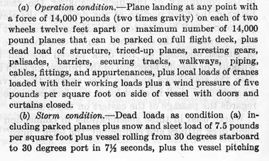
This is very interesting and es expected much more complex. From p 162:
1753546018467.png

So it contains
-a specific landing limit for a typical airplane, defined by speed and wheel distance. Slower plane -> higher weight?
-a static limit that concerns the entire structure ("storm condition" probably being the relevant one for static limits). Reduce nr of planes -> higher weight?
 
Ok, this is for dynamic loads. The question is still, what is the standard? For example, for roads you have an acceptable degree of wear and tear, and limits depending namely on the axle load.
You might try Lloyds Register Naval Ships Rules Vol. 1 Part 4 Chapter 2 Section 10 Aircraft Operations, which ought to tell you all you want to know about the standard. I'm sure the US Navy has its own standard for such things, but it won't yield wildly different results.

The key figure is that design is based on the stresses experienced by the deck and supporting structure. Parking areas are subject to different rules than landing areas - i.e. static load rather than dynamic, but based on maximum weight of the aircraft rather than landing weight.

The impact of any deformation is assessed, but that isn't the governing factor. There isn't a special 'wear and tear' allowance, but there are minimum thickness requirements, with provision for special consideration if sheathing is provided and for an enhanced 1.5mm corrosion allowance.

The rules don't particularly care whether you use steel, aluminium, wood, or cheese, provided you use enough of it in the right places and adopt any associated design measures.
 
You might try Lloyds Register Naval Ships Rules Vol. 1 Part 4 Chapter 2 Section 10 Aircraft Operations, which ought to tell you all you want to know about the standard. I'm sure the US Navy has its own standard for such things, but it won't yield wildly different results.

I assume that this applies regardless, pt 10.5.: "Wty = landing or static load, on the tyre print, in kN; with the centre of gravity in a position that causes the highest load." So again making much more sense than "THE" limit of say 44k lbs static for a carrier.

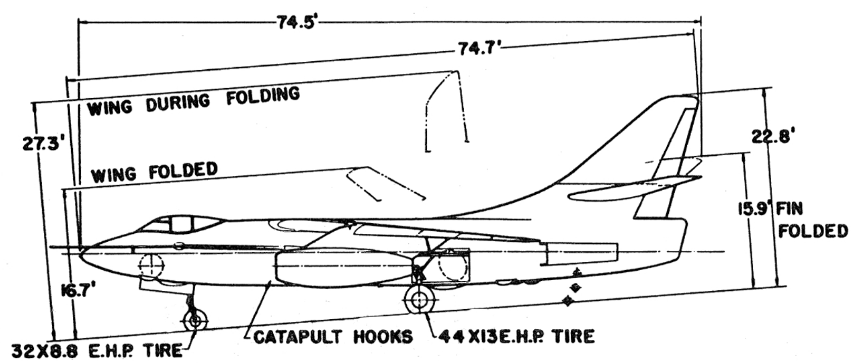
From a quick look, for example the E-2 has a larger tyre than the F-4; and the A-3, a larger tyre than the E-2. That should give pretty substantial differences for tyre print.

The rules don't particularly care whether you use steel, aluminium, wood, or cheese, provided you use enough of it in the right places and adopt any associated design measures.

I am certain that somewhere in UK archives, the project for the cheese flight deck is to be found as the follow-up to the rubber deck.
 
So again making much more sense than "THE" limit of say 44k lbs static for a carrier.
Precisely so. Modern practice is that each individual combination of aircraft and deck needs to be assessed as acceptable. Historic practice may not have been quite so rigorous.

In the case of that passage - an aircraft with a forward C.G. will have more weight on the nose gear and less on the main gear. An aircraft with an aft C.G. will be the reverse. You're expected to design for the worst case, whichever that might be.
I am certain that somewhere in UK archives, the project for the cheese flight deck is to be found as the follow-up to the rubber deck.
It's my mission to get it in there eventually. Cheese is my go-to example for 'this is a truly awful structural material'.
 
An interesting, if small note on modern US carriers is, that when they dock, they always tie up starboard side to the pier. That side has the sponsons and connections for shore power, CHT (sewer), water, etc., along with allowing multiple brows for leaving and coming aboard ship. Because of the angle and the way the port side is made, all of that isn't possible on that side. There are limited hook ups on the port side, just in case, but starboard is heavily preferred.
 
An interesting, if small note on modern US carriers is, that when they dock, they always tie up starboard side to the pier. That side has the sponsons and connections for shore power, CHT (sewer), water, etc., along with allowing multiple brows for leaving and coming aboard ship. Because of the angle and the way the port side is made, all of that isn't possible on that side. There are limited hook ups on the port side, just in case, but starboard is heavily preferred.
Plus there are 2-3 deck edge elevators there available to use for access.
 
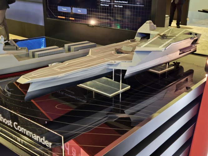
Trimaran design makes me wonder where the hangar is.

It's obviously supposed to be stealthy which means no aircraft kept on deck.
 
No, the Japanese didn't use deck parks. They would spot the planes on deck for a strike. The dive bombers got their bombs loaded on the flight deck while the torpedo planes came up loaded. All the aircraft would already be fueled.

The elevators were even designed specifically for each type of aircraft as the hanger arrangements had specific areas for each type to be stored.

What the IJN didn't do was leave planes on the flight deck for days on end (deck park) whether there was a strike or not.
In fact , Japanese used deck park but its not often.
The Japanese believed there were the following challenges:
* Weather resistance of their equipment; they had lost many ships and aircraft in typhoons in the past. Also, this is my guess, but there may have been issues with the paint.
* Narrow deck; even with many aircraft deck park in the open, they couldn't line up a sufficient number of attack aircraft.For the reasons above, Japan focused on anti-submarine patrol and CAP aircraft, and deck park them in the open.
http://www.warbirds.jp/truth/ijn_cv.html
http://www.warbirds.jp/ansq/11/A2002406.html
 

Similar threads

Back
Top Bottom