3-2-1 Context and Start of the project
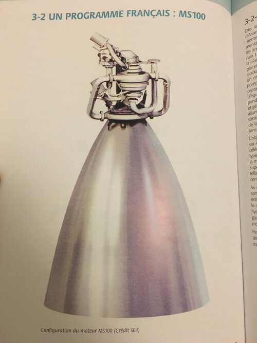
As soon as the development of the Vulcain engine and Ariane 5 was completed, the question arose of its evolution to increase performance and thus be able to respond to the increase in mass of geostationary satellites in the 2000s. In 1996, the Vulcain 2, derived from the Vulcain 1, with increased thrust (115 to 135 t) was already on the drawing board, and the question of replacing the Aestus engine of the storable upper stage was also raised, for which DASA (Ottobrunn center) proposed a 50 kN thrust engine equipped with a Rocketdyne turbopump. This orientation was not considered acceptable by SEP because it would open the door to the introduction of American equipment on Ariane 5. SEP decided to respond by proposing a storable engine with a turbopump and gas generator of approximately 100 kN thrust, and reignitable. This will be the MS100, the industrial assembly being similar to that of the HM7 engine, DASA being responsible for the combustion chamber, and SEP for the “powerpack” (turbopump assembly, gas generator, regulation).
The objective being to allow a first flight in 2003 on Ariane 5 Evolution, the management of Vernon decided to accelerate the design and manufacture of a first prototype of "powerpack" that could be tested on the bench around mid-98. This choice was favored to have a re-ignitable upper stage and to achieve a satellite capacity of 9 t in GTO orbit, corresponding to a double launch of two geostationary satellites of 4.5 t.
At the start of the project, at the beginning of 1997, the specifications were not yet fixed: the thrust of the engine was between 80 and 120 kN, the oxidizer was nitrogen peroxide, the choice of UDMH or MMH (monomethylhydrazine) fuel had not yet been made. A gas generator cycle was quickly chosen to preserve the achievements of the Viking engine.
While a dedicated team studies the engine, the Turbomachinery, Combustion and Equipment Design Units tackle the components that will make up the "powerpack". An initial three-month phase allows the specifications necessary for dimensioning the subassemblies to be specified, the different architectures of the engine and stage to be studied, and different equipment concepts to be evaluated in order to make the best choice. This preliminary study phase culminates in a System Concept Review (RCS) held in April 1997.
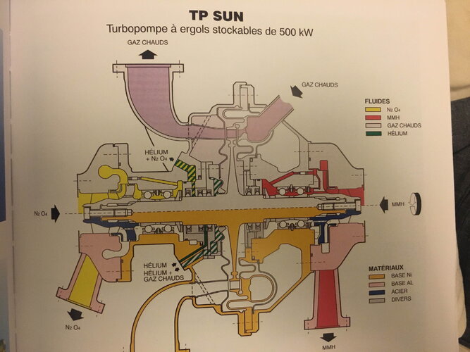
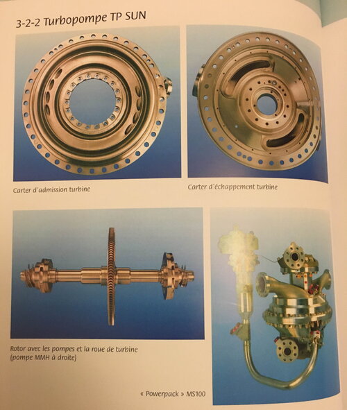
For the turbopump, different architectures are studied: two separate turbopumps, and a single single-shaft machine with the turbine in the center or the turbine cantilevered (in this case, the propellant pumps are adjacent). The turbopump selected will be called TP SUN (for Stockable UDMH N2O4).
Similarly for the control valves or the gas generator, this period is used to research the best technologies. The project is organized around concurrent engineering (coordination between the different project stakeholders).Monthly meetings are organized at the engine level, and weekly in the Design Units. The manufacturing, laboratory, and testing teams are involved in the work from the start to integrate their constraints into the sizing studies.
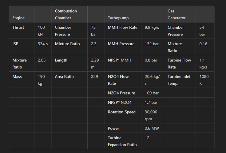
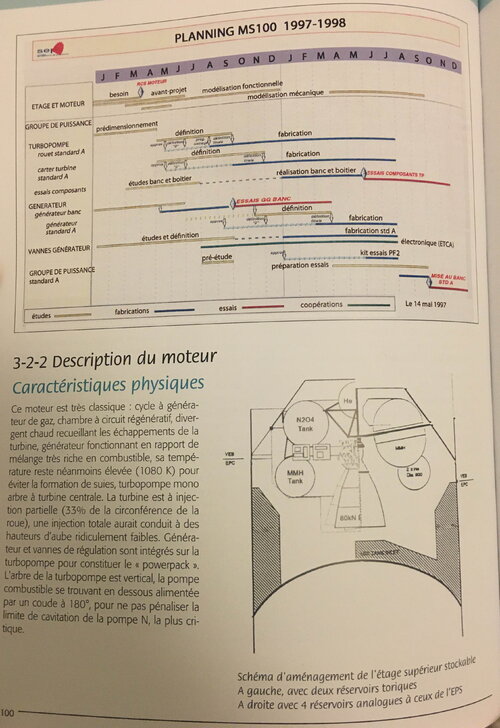
The RCS allows the project to be presented to managers and to freeze the choices of architecture and technologies, as well as the specifications of the "powerpack". The thrust chosen for the engine is 100 kN, the fuel chosen is initially UDMH, then we will move on to MMH, without any significant impact on the sizing of the subsystems (the difference in density has a small influence on the fuel pump and the generator). The schedule for May 97 provides for starting the generator tests on the SYBIL bench in Villaroche in the fourth quarter and the tests of turbopump components (bearings and dynamic seals) from June 98. The tests of the complete "powerpack" are planned for the fourth quarter of 98
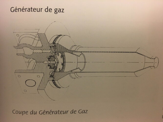
This engine is very classic: gas generator cycle, regenerative circuit chamber, hot divergent collecting the turbine exhausts, generator operating in a very fuel-rich mixture ratio, its temperature nevertheless remains high (1080 K) to avoid the formation of soot, single-shaft turbopump with central turbine. The turbine is partially injected (33% of the wheel circumference), total injection would have led to ridiculously low blade heights. Generator and control valves are integrated on the turbopump to form the "powerpack". The turbopump shaft is vertical, the fuel pump being located below, supplied by a 180° elbow, so as not to penalize the cavitation limit of the N pump, the most critical
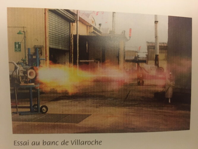
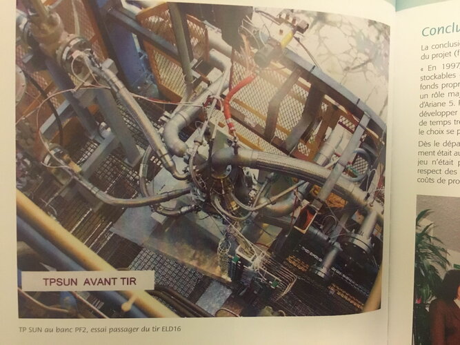
Once the architectural choices have been finalized, the Design Units tackle the detailed definition of the valves, generator and turbopump. The generator begins its tests on the SYBIL bench in Villaroche in October 97. Sixteen tests will be carried out to finalize the choice of the injection configuration, check the correct temperature setting, check the stratification, and test the combustion stability by bomb tests. The results will be satisfactory. At the same time, the long-cycle supplies of the turbopump parts (foundries, forged blanks) are launched in order to have a first prototype by mid-98. The test means for the turbopump are also studied and prepared: component bench to test the bearings and dynamic seals, PF2 bench for testing the integrated turbopump and gas generator

