Wasserfall antiaircraft rocket

The British and US ignored it almost entirely.
Not quite.

1776699428460.png


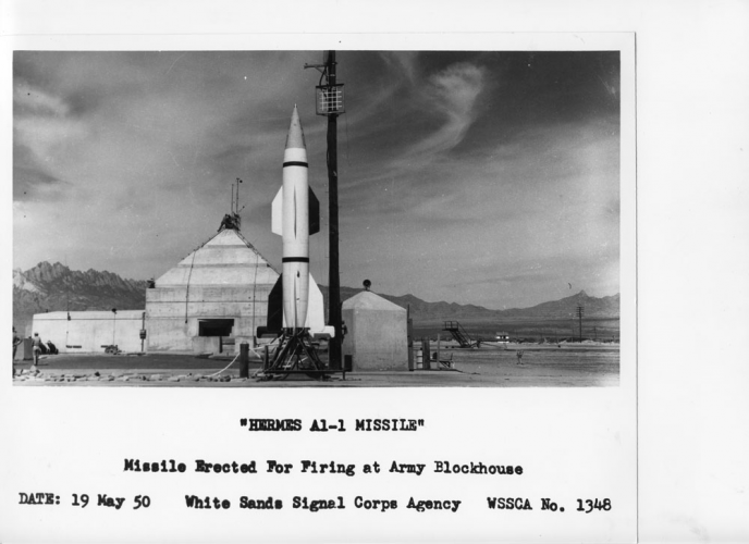
US army tried to make Wasserfall work as Hermes A-1 project, but the results were as poor as in USSR. None of test flights were sucsessfull. In 1950 (the same year as USSR), US army give up on Hermes as surface-to-air missile, but still hoped to use it as surface-to-surface missile. Several Hermes A-3 prototypes were build and tested from 1951 till 1954, but the conclusion was, that it simply didn't worth the efforts.
 
Not quite.

View attachment 809722


US army tried to make Wasserfall work as Hermes A-1 project, but the results were as poor as in USSR. None of test flights were sucsessfull. In 1950 (the same year as USSR), US army give up on Hermes as surface-to-air missile, but still hoped to use it as surface-to-surface missile. Several Hermes A-3 prototypes were build and tested from 1951 till 1954, but the conclusion was, that it simply didn't worth the efforts.
Almost entirely. GE was assigned the Hermes as a SAM as part of that program. GE immediately replaced the German P IX engine with one of GE's own design running on alcohol and LOX or RFNA. GE launched exactly 6 missiles of this type through 1950 before the program was dropped. None of the GE missiles had some external guidance system in use. The results of those 6 launches were so poor, and Nike was at that point looking very promising, that the US Army didn't want to waste more time and resources with the A-1 series.

Other designs, of all-US origin, replaced it in the program.

hermes-line1.gif
 
I’ve continued to dig on the question of whether the C2 Wasserfall jettisoned its thrust vector control vanes once its velocity was sufficient to depend on aerodynamic control.

Sources vary. A few say its was planned to improve efficiency but the vanes burned off anyway so wasn’t needed. A few others say the vanes burned unevenly, causing asymmetric thrust, making jettison critical.

Ive found a very good technical article on Wasserfall in a 1951 Interavia magazine by Rudolf Reichel. I think Reichel was at Peenemunde so can be regarded as a primary source ? His article stated that it was set up for vane jettison, each vane and backplate assembly being held in a slide rail by a squib operated bolt.

I have yet not found a wartime German language technical report that confirms this, so would say squib jettison on C2 is 80 percent but not certain.

I think a fair number of early missiles that followed the war also used graphite TVC vanes. Does anyone know if any of those had a scheme to jettison vanes once up to speed ?
From what I can find, the vanes had to be jettisoned. They were used in conjunction with Rüse, a telemetry set used for guidance during the vertical stage of flight to keep the missile stable. The controls on the fins were locked during this period. At the cant over point where the missile turned to start heading towards the target, Rüse was discontinued and the fire control guidance system took over using the control surfaces on the fins. Having the graphite veins remain in place would just fight those controls and they were no longer needed. Worse, if they stayed in place and one or more moved since there was no longer positive control of them, they could send the missile badly off course.

Rüse was necessary because the minimum range for any of the radar guidance systems--the optical ones just were not going to work at all, PERIOD!--was so large that you couldn't gather the missile into the tracking beam in the early stage of the flight. Rüse was already in use with the A4 / V-2 for this purpose so that made it convenient to use. This is what the Swedes gave the British as the so-called guidance system for Wasserfall BTW.

I looked at the Wasserfalls and their clones at White Sands and this appears to be accurate. The museum staff couldn't tell me for sure about that feature as they didn't know. GE who operated the few shots made, has never returned my inquiries on this and likely doesn't know today either. So, I did try to verify my observations. The missiles there are all missing their graphite veins.
 
C2 Wasserfall jettisoned its thrust vector control vanes

Report EW 2142, December 1944
5. Strahlruder
The trials with silicon carbide jet vanes for the material changeover have been successful so far. The state porcelain factory now intends to produce vanes made of corundum. The test stand has been converted for trials of jettisoning the jet vanes.

January 11, 1945
Jettisoning of the Jet Vanes
Following a meeting on January 10, 1945, it was decided, in agreement with EW 214 and Herr Patt, that the jet vanes will now be jettisoned after 12 seconds of flight.

Source: Bundesarchiv
Signature: RH 8/1302 Pages: 12, 42, 114
Direct link:
https://invenio.bundesarchiv.de/invenio/direktlink/0c10fdae-81bf-450c-a13f-d5824194df1e/

June 5, 1944
Aggregat C 2/E 2
Various antenna designs are available for the onboard equipment of the Wasserfall.

Source: Bundesarchiv
Signature: RH 8/1298; Page: 11 (Drawings)

Direct link:
https://invenio.bundesarchiv.de/invenio/direktlink/bd47d90e-0bb7-4ff1-8dcd-e5cd791de2c8/
 
Report EW 2142, December 1944
5. Strahlruder
The trials with silicon carbide jet vanes for the material changeover have been successful so far. The state porcelain factory now intends to produce vanes made of corundum. The test stand has been converted for trials of jettisoning the jet vanes.

January 11, 1945
Jettisoning of the Jet Vanes
Following a meeting on January 10, 1945, it was decided, in agreement with EW 214 and Herr Patt, that the jet vanes will now be jettisoned after 12 seconds of flight.

Source: Bundesarchiv
Signature: RH 8/1302 Pages: 12, 42, 114
Direct link:
https://invenio.bundesarchiv.de/invenio/direktlink/0c10fdae-81bf-450c-a13f-d5824194df1e/

June 5, 1944
Aggregat C 2/E 2
Various antenna designs are available for the onboard equipment of the Wasserfall.

Source: Bundesarchiv
Signature: RH 8/1298; Page: 11 (Drawings)

Direct link:
https://invenio.bundesarchiv.de/invenio/direktlink/bd47d90e-0bb7-4ff1-8dcd-e5cd791de2c8/
These are amazing documents. Thanks again Moin for making these fantastic documents available to the forum !


Excellent proof that the idea of jet vane jettison wasn't a post war invention, but survived as a planned feature all the way through the truncated flight test programme.
 
Calling the Wasserfall engine the P IX is an error, possibly introduced by Roland Pocock in his 1960s book on German missiles. According the German wartime documents, P IX is the static test stand for both the Wasserfall engine prior to installation and the all up missile, with facilities to measure and adjust thrust, fuel flows etc. None of the german documents that I have translated ever refer to the Wasserfall engine as P IX, only the test stand.

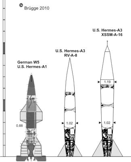
The Brugge 2010 diagram above is misleading in that it shows a single internal layout for both Wasserfall and Hermes A1. It wrong for Wasserfall as, for instance, the big spherical pressurised nitrogen tank is missing. All Wasserfall variants build or conceived had this. I cant really say if its a good fit for Hermes A1 as the Americans did a much better job of archiving the German design drawings than they did for their own. Calling the Wasserfall the "German W5" is also an error. Wasserfall was usually called Wasserfall, occassionally (usually by outside agencies) its older Roth design office C2 designation was used. The W3, W4, W5 etc. were batch built variant used (or intended for) the uncompleted flight test programme. W5 was just a glimmer in the meeting minutes when Peenemunde was evacuated. The error of calling the Wasserfall W5 (so beloved of model kit manufacturers) and confusing it with the never built operational variant was introduced in the post war allied intelligence documents.

I think its also a gross oversimplication to consider the Hermes A1 as a "US Wasserfall". It has virtually the same (but not identical) aerodynamic form and control fin/jet vane layout. But different engine, different fuel, different oxidiser, different fuel regulator, different materials, different internal layout, different gyros, different flight control computer, different servo actuators, different guidance link transmitter & receiver and different guidance system. I don't know if changed to use Imperial threads and fixings but would love to know. So while the Hermes team struggled to get Hermes A1 off the ground, its not as simple as they were struggling to "make Wasserfall work". They were struggling to make a pretty much wholly new but Wasserfall shaped missile work, shortcutting the amount of wind tunnel time needed by re-using the aerodynamic form.
 
Calling the Wasserfall engine the P IX is an error, possibly introduced by Roland Pocock in his 1960s book on German missiles. According the German wartime documents, P IX is the static test stand for both the Wasserfall engine prior to installation and the all up missile, with facilities to measure and adjust thrust, fuel flows etc. None of the german documents that I have translated ever refer to the Wasserfall engine as P IX, only the test stand.

The Brugge 2010 diagram above is misleading in that it shows a single internal layout for both Wasserfall and Hermes A1. It wrong for Wasserfall as, for instance, the big spherical pressurised nitrogen tank is missing. All Wasserfall variants build or conceived had this. I cant really say if its a good fit for Hermes A1 as the Americans did a much better job of archiving the German design drawings than they did for their own. Calling the Wasserfall the "German W5" is also an error. Wasserfall was usually called Wasserfall, occassionally (usually by outside agencies) its older Roth design office C2 designation was used. The W3, W4, W5 etc. were batch built variant used (or intended for) the uncompleted flight test programme. W5 was just a glimmer in the meeting minutes when Peenemunde was evacuated. The error of calling the Wasserfall W5 (so beloved of model kit manufacturers) and confusing it with the never built operational variant was introduced in the post war allied intelligence documents.

I think its also a gross oversimplication to consider the Hermes A1 as a "US Wasserfall". It has virtually the same (but not identical) aerodynamic form and control fin/jet vane layout. But different engine, different fuel, different oxidiser, different fuel regulator, different materials, different internal layout, different gyros, different flight control computer, different servo actuators, different guidance link transmitter & receiver and different guidance system. I don't know if changed to use Imperial threads and fixings but would love to know. So while the Hermes team struggled to get Hermes A1 off the ground, its not as simple as they were struggling to "make Wasserfall work". They were struggling to make a pretty much wholly new but Wasserfall shaped missile work, shortcutting the amount of wind tunnel time needed by re-using the aerodynamic form.
I wish I had thought of it before but confusing Wasserfall and Hermes A1 is like confusing a Dolphin with an Ichthyosaur. The external shape is very similar, as they both operate in a similar way in the same medium, but the insides .... different. Any cutaway diagram labelled "Ichthyosaur / Dolphin" should be viewed with equal suspicion.
 
Calling the Wasserfall engine the P IX is an error, possibly introduced by Roland Pocock in his 1960s book on German missiles. According the German wartime documents, P IX is the static test stand for both the Wasserfall engine prior to installation and the all up missile, with facilities to measure and adjust thrust, fuel flows etc. None of the german documents that I have translated ever refer to the Wasserfall engine as P IX, only the test stand.

I haven't found any other official designation for the engine, so I've usually gone with P IX.
The Brugge 2010 diagram above is misleading in that it shows a single internal layout for both Wasserfall and Hermes A1. It wrong for Wasserfall as, for instance, the big spherical pressurised nitrogen tank is missing. All Wasserfall variants build or conceived had this. I cant really say if its a good fit for Hermes A1 as the Americans did a much better job of archiving the German design drawings than they did for their own. Calling the Wasserfall the "German W5" is also an error. Wasserfall was usually called Wasserfall, occassionally (usually by outside agencies) its older Roth design office C2 designation was used. The W3, W4, W5 etc. were batch built variant used (or intended for) the uncompleted flight test programme. W5 was just a glimmer in the meeting minutes when Peenemunde was evacuated. The error of calling the Wasserfall W5 (so beloved of model kit manufacturers) and confusing it with the never built operational variant was introduced in the post war allied intelligence documents.

I tossed that drawing up just as a general reference to show that the Hermes program rapidly advanced beyond the Wasserfall design. I really didn't intend it as one using many details of those missiles. So, it is the C2, not W5. Good to know. Does that apply to the whole Wasserfall test series?
I think its also a gross oversimplication to consider the Hermes A1 as a "US Wasserfall". It has virtually the same (but not identical) aerodynamic form and control fin/jet vane layout. But different engine, different fuel, different oxidiser, different fuel regulator, different materials, different internal layout, different gyros, different flight control computer, different servo actuators, different guidance link transmitter & receiver and different guidance system. I don't know if changed to use Imperial threads and fixings but would love to know. So while the Hermes team struggled to get Hermes A1 off the ground, its not as simple as they were struggling to "make Wasserfall work". They were struggling to make a pretty much wholly new but Wasserfall shaped missile work, shortcutting the amount of wind tunnel time needed by re-using the aerodynamic form.

Again, I wasn't getting into the weeds here. You're correct. GE put in an engine and fuel system they designed at their Malta NY facility right from the start and used LOX and methanol as fuel. All of the electronics are US designed as happened gradually with captured A4 / V2 rockets. Hermes pretty quickly steered away from being a SAM program once it was clear that Nike was going to succeed as a design. It instead became almost totally an R&D program into general ballistic missile design instead.

I doubt that White Sands would be happy with me taking things apart on one of the surviving Wasserfall clones they have on display so I can't really tell you what screw threads were in use on it.
 
April 20, 1943
Design of a guided liquid-fueled rocket for engaging aerial targets.
Parts: A - E

Part: A
Entwurf einer gesteuerten Flüssigkeitsrakete zur Bekämpfung von Flugzielen (Projekt „Wasserfall“)

Also includes:
Statische Untersuchungen W1

Source: Bundesarchiv
Signatur: RH 8/3641; Page: 99 - 207, 237 - 302

Direct Link:
https://invenio.bundesarchiv.de/invenio/direktlink/d993c5a8-0763-4785-9f84-7838e39104b3/

Part: B
Entwurf einer gesteuerten Flüssigkeitsrakete zur Bekämpfung von Flugzielen (Projekt „Wasserfall“)
- Control of the flak missile

Source: Bundesarchiv
Signatur: RH 8/3647; Page: Page: 73 - 167

Direct Link:
https://invenio.bundesarchiv.de/invenio/direktlink/9db32af8-7c8b-4427-9a7b-b136ff58703f/

Part: E
Entwurf einer gesteuerten Flüssigkeitsrakete zur Bekämpfung von Flugzielen (Projekt „Wasserfall“)
- Manufacturing, raw material and fuel requirements for anti-aircraft missiles

Source: Bundesarchiv
Signatur: RH 8/3655; Page: Page: 20 - 99

Direct Link:
https://invenio.bundesarchiv.de/invenio/direktlink/870689a9-e4e6-4b20-b542-a8328111d0af/
 
September - October 1942
Tactical and technical requirements for the development of anti-aircraft missiles, October 22, 1942. Discussion in the HAP on September 26, 1942. Development program of anti-aircraft artillery (guided anti-aircraft missile).
HAP will investigate three propulsion systems:
- Pure "Salbei" rocket
- "Salbei" rocket with powder rocket booster
- Pure powder rocket

Source: Bundesarchiv
Signatur: RH 8/1258

Direct Link:
https://invenio.bundesarchiv.de/invenio/direktlink/46f9b3d4-7512-4c78-afb2-0fcaaaa2cf5a/

November 1942
In the report dated November 2, 1942 ("Die Entwicklung einer gesteuerten Flakrakete," HAP Archive Number 58/3), Wernher von Braun proposes three different solutions for a guided anti-aircraft rocket:
- Solid propellant C1
- Liquid-propellant C2
- Two-stage C3
Unfortunately, I do not have this report.

Perhaps someone knows more about the C1 and C3 designs?

C3 Wasserfall "Rheinmetall"
https://www.secretprojects.co.uk/threads/wasserfall-antiaircraft-rocket.3067/post-63824
Source:
Bundesarchiv Files
Signatur: RH 8/3641; Page: 243
https://en.wikipedia.org/wiki/Wasserfall
 
Last edited:
I haven't found any other official designation for the engine, so I've usually gone with P IX.
I thought it was P IX for ages.... I guess Waterfall Engine (Wasserfall Ofen) was sufficient so it never got a more official sounding designation.


I tossed that drawing up just as a general reference to show that the Hermes program rapidly advanced beyond the Wasserfall design. I really didn't intend it as one using many details of those missiles. So, it is the C2, not W5. Good to know. Does that apply to the whole Wasserfall test series?
As stated by Moin1900 Wasserfall was C2 in the original SAM design study. C1 was was a solid fuel option. Evidence for a C3 option is weaker but I'm still searching.

The studied SAM variants were prefixed with C because Ballistic Missiles had already got A (e.g. the V2 was really A4.) and JATO engines got the B prefix.

Because the liquid fuel SAM was selected for onward development, the C2 designation stuck for a while. But very soon it was also named Wasserfall and thats name the engineers used in their documents thereafter. A few more sober types, like the Aerodynamics Institute at Peenemunde, preferred the C2 designation and continued to use it to the end of the war. On most projects there are always a few die hards who hate the silly name given by the marketing guys.

So techncially the SAM we are discussing is both C2 and Wasserfall. But Wasserfall is vastly more common in the German literature so thats what I try to use.

Regarding prototype production batches, the first two were V1 (first two launches) and V2 (next 5). Theres a very good photo of a Wasserfall on its launch stand, with umbilicals attached. If you look closely you can see V2 stencilled on the nose.

But then disaster struck, when the propaganda ministry badged the airforces cruise missile and the A4 as V1 and V2 respectively. So a memo went out, which we have in the archive, along the lines of "okay chaps, from here on in, the next batches are W3, W4 etc. Forget that V1, V2 stuff....".

W3 batch was built and flown. The majority of the test flown rounds were of the W3 batch. Somewhere between 25 and 30 rounds probably. As we dont know for certain how many flight tests were conducted overall, this number is hazy.

W4 batch was built but its not clear whether any flew. I think the survivors in the USA and UK are probably from W4 batch, which was shipped out of Peenemunde when it was evacuated.

The design changes that would have been included in a W5 batch were being defined when Peenemunde was evacuated, so it seems very unlikely any were built.

Many books and articles say that there was a reduced size Wasserfall called W10. This is what we used to call in the UK "complete cobblers". The reduced size variant was proposed in the very last days of the war and was just a study document. Never got near to being an official batch designation. Similarly theres no evidence for W6 to W9.

All of this comes from the archived German technical meetings, where production batches are scoped and re-scoped on a monthly basis, so its all quite confusing to say the least. Probably most of the confusion comes from immediate post war intelligence summaries produced from interviewing german engineers. Inevitably, this wasnt 100% accurate or consistent, depending on the knowlege and recollection of the interviewee.
Again, I wasn't getting into the weeds here. You're correct. GE put in an engine and fuel system they designed at their Malta NY facility right from the start and used LOX and methanol as fuel. All of the electronics are US designed as happened gradually with captured A4 / V2 rockets. Hermes pretty quickly steered away from being a SAM program once it was clear that Nike was going to succeed as a design. It instead became almost totally an R&D program into general ballistic missile design instead.

I doubt that White Sands would be happy with me taking things apart on one of the surviving Wasserfall clones they have on display so I can't really tell you what screw threads were in use on it.

I agree on the question of screw threads :) if you do get to White Sands or Huntsville, an interesting experiment would be to put a magnet on the outer skin and see if it sticks. Its possible they used aluminium for the airframes. The Peenemunde team certainly would have if they could get hold of it....
 
I thought it was P IX for ages.... I guess Waterfall Engine (Wasserfall Ofen) was sufficient so it never got a more official sounding designation.

I think I'll stick with P IX and just add an * to note that it wasn't official. That way it's easier to work into written material.
As stated by Moin1900 Wasserfall was C2 in the original SAM design study. C1 was was a solid fuel option. Evidence for a C3 option is weaker but I'm still searching.

The studied SAM variants were prefixed with C because Ballistic Missiles had already got A (e.g. the V2 was really A4.) and JATO engines got the B prefix.

Because the liquid fuel SAM was selected for onward development, the C2 designation stuck for a while. But very soon it was also named Wasserfall and thats name the engineers used in their documents thereafter. A few more sober types, like the Aerodynamics Institute at Peenemunde, preferred the C2 designation and continued to use it to the end of the war. On most projects there are always a few die hards who hate the silly name given by the marketing guys.

So techncially the SAM we are discussing is both C2 and Wasserfall. But Wasserfall is vastly more common in the German literature so thats what I try to use.

Regarding prototype production batches, the first two were V1 (first two launches) and V2 (next 5). Theres a very good photo of a Wasserfall on its launch stand, with umbilicals attached. If you look closely you can see V2 stencilled on the nose.

But then disaster struck, when the propaganda ministry badged the airforces cruise missile and the A4 as V1 and V2 respectively. So a memo went out, which we have in the archive, along the lines of "okay chaps, from here on in, the next batches are W3, W4 etc. Forget that V1, V2 stuff....".

W3 batch was built and flown. The majority of the test flown rounds were of the W3 batch. Somewhere between 25 and 30 rounds probably. As we dont know for certain how many flight tests were conducted overall, this number is hazy.

W4 batch was built but its not clear whether any flew. I think the survivors in the USA and UK are probably from W4 batch, which was shipped out of Peenemunde when it was evacuated.

The design changes that would have been included in a W5 batch were being defined when Peenemunde was evacuated, so it seems very unlikely any were built.

Many books and articles say that there was a reduced size Wasserfall called W10. This is what we used to call in the UK "complete cobblers". The reduced size variant was proposed in the very last days of the war and was just a study document. Never got near to being an official batch designation. Similarly theres no evidence for W6 to W9.

All of this comes from the archived German technical meetings, where production batches are scoped and re-scoped on a monthly basis, so its all quite confusing to say the least. Probably most of the confusion comes from immediate post war intelligence summaries produced from interviewing german engineers. Inevitably, this wasnt 100% accurate or consistent, depending on the knowlege and recollection of the interviewee.

From what I can see, most SAMs only got some manufacturer's designation, if that, and those aren't always clear. For example, most texts list the Rheinmetall Rhientocter missile as the R I and III with the II variant left unexplained. Rheinmetall hasn't answered any of my requests for information on this missile and documentation is spotty at best. From what I can tell, if the R I, II, III designation is correct, the II is the variant without the boxed in booster tail fins on it.

The W1, 5, 10 is convenient. Maybe again with and *. For a lot of SAM development, the Conrad RLM 109-613 rocket engine is a forgotten thing. It's all really iffy in the confusion of defeat if you ask me. I see the W-10* as something proposed on paper and never got beyond that.

From everything I've looked at, Wasserfall was very much experimental to the end of the program with lots of issues with the missile, not to mention the guidance system which was really almost $h!+. It wasn't a viable SAM and wasn't likely to be any time soon. Postwar, the Russians really tried hard to make it one and failed. NII 88 tried for about 5 years to make it work and couldn't get there. The US ditched it almost immediately. The British and French didn't even bother. The former because they saw it as "The Germans lost. How good could it be?" while the later had no access to it.

The problem is that these late-war German projects are not well documented and there's considerable confusion on what was going on. That's kind of expected given the state of things in Germany in late 1944.
I agree on the question of screw threads :) if you do get to White Sands or Huntsville, an interesting experiment would be to put a magnet on the outer skin and see if it sticks. Its possible they used aluminium for the airframes. The Peenemunde team certainly would have if they could get hold of it....

I looked at one example of a German V-2 at the NM Museum of Space History (I don't recommend it as a visit) and the whole thing was rusted over. That pretty much screams "STEEL!"

APNQkAEqggazMWKUGXpCjD6LAvCmD7yAW_vmp79zs1aLH6FP7beZo3s4rHtI9ypgWQMRYP_RXj5PaTHLIJUSoCWyNtnYhz0LvsuAU_zZEKqNU7ymBQrwhSCfI7fqYIlpmwcinvm7DGqF=w203-h152-k-no


Yes, inside and outside, it is solidly rusted over. There is nothing I recognized as aluminum oxidation.
 
Last edited:
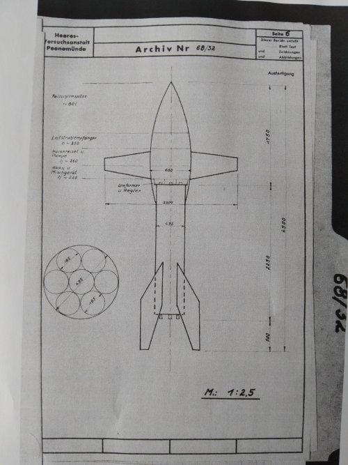
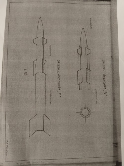
These two photos are from Wasserfall design study documents. Sorry about indifferent quality.

The first is of the C1, a proposed single stage solid fuel Flak missile, from the early study days when Wasserfall was just "C2". The other picture is a much later study, that revisits the option of having a solid rocket booster and a liquid fuelled sustain engine. Two options, one along the lines of Nike, the other more Bloodhound/Thunderbird/Sea Slug. Dated as Feb 44, same month as first Wasserfall development test flight.
 

Attachments

  • 17774753250176972556629511143160.jpg
    17774753250176972556629511143160.jpg
    3.7 MB · Views: 82
  • 17774754043355431928748273661493.jpg
    17774754043355431928748273661493.jpg
    4.4 MB · Views: 85
These two photos are from Wasserfall design study documents. Sorry about indifferent quality.

The first is of the C1, a proposed single stage solid fuel Flak missile, from the early study days when Wasserfall was just "C2". The other picture is a much later study, that revisits the option of having a solid rocket booster and a liquid fuelled sustain engine. Two options, one along the lines of Nike, the other more Bloodhound/Thunderbird/Sea Slug. Dated as Feb 44, same month as first Wasserfall development test flight.
Well the one on the left is a variant of an early design discussed some in Die deutsche Luftfahrt Die Pfeilflügelentwicklung in Deutshcland bis 1945 by Han-Ulrich Meier. p 377-378
 
View attachment 809185
Actually... I believe I am qualified to answer this question. Here we are discussing first-generation infrared seekers:

The core component of a first-generation infrared guidance system is a partially blackened transparent plastic disk known as a reticle. The image shows one type of reticle, called the "rising sun reticle" (translated from Chinese; I am not sure of its foreign name).

In a missile seeker, the following parts are present:

[Optical components] – [Reticle] – [Single photosensitive element]

You can see that half of the reticle is completely blackened, while the other half has evenly spaced stripes.

Now, a target appears in the field of view. With only a single photosensitive element, we cannot directly extract the target's angular information. The reticle, however, intelligently modulates the continuous signal to tell the guidance system where the target is.

The target signal passes through the optical components and is projected onto the reticle. Through the reticle, the target causes a flickering effect. From this flicker, the guidance system behind the photosensitive element can extract information. The specific method is as follows:

First, we need to break down the angle between the missile and the target. Here, we decompose it into the angle between the missile's axis and the target, and the angle formed on the plane normal to the missile axis relative to a reference direction (the specific direction is irrelevant, as long as it is fixed relative to the missile).

When the light source falls on the striped region, it produces a continuously flickering signal. If the target deviates significantly from the missile's axis, the flickering signal will have a higher amplitude; if the deviation is small, the signal amplitude will be lower.

When the light source falls on the blackened semicircle, the guidance system uses this period of prolonged signal interruption, along with the rotation speed and position of the reticle, to calculate the angle on the missile's normal plane relative to the reference direction (again, the specific direction is irrelevant, as long as it is fixed relative to the missile).

By using the two parts of the reticle to calculate these two angles separately, the complete angular information of the target is obtained.

The other part of this equation is that the point source of the target will flicker (thus generating a signal with a frequency determined by the spin speed of the disc and the number of divisions) while the diffuse background will produce a direct-current voltage which (in an ideal world) can be filtered out and thereby ignored. In the real world it's a different matter, and reflections off of clouds, the water, and even the sun itself were often sufficiently "point source" to fool the early missiles into taking a different course (as, of course, are countermeasure flares).
 
The other part of this equation is that the point source of the target will flicker (thus generating a signal with a frequency determined by the spin speed of the disc and the number of divisions) while the diffuse background will produce a direct-current voltage which (in an ideal world) can be filtered out and thereby ignored. In the real world it's a different matter, and reflections off of clouds, the water, and even the sun itself were often sufficiently "point source" to fool the early missiles into taking a different course (as, of course, are countermeasure flares).
This would be solved in the 60's by use of liquid nitrogen cooling the seeker, but the early first-generation ones didn't have that luxury installed yet. The seeker heads also didn't have anything close to the ability to bandpass only a narrow range of frequencies. That was the next big improvement that came in the early 80's.
 
W 10
January 29 - February 3, 1945
Project W 10
Project work on W 10 has commenced. An overview is to be submitted to EW 205 by February 10.

February 4th - February 10th, 1945
Gerät W 10
Design work on the W 10 continued. Construction details and weights were determined.

February 12-17, 1945
The following drawings were newly completed:
- Gerät W 10 SkW 989B
Gerät W 10
Project work for the Device W 10 continued, and the engine overview, a device overview, and the center of gravity and moment of inertia diagrams were completed.

Source: Bundesarchiv
"Weekly Reports EW (Technical)"
March 6, 1944 - February 17, 1945
Signatur: RH 8/1264; Page: 4, 6, 8

Direct Link:
https://invenio.bundesarchiv.de/invenio/direktlink/d72f1270-5f13-40b8-bea4-6715fd4128df/


W10 Drawings:
SkW 989B Gerät W 10, February 1945
SkW 999D Comparison W10 - W5, February 1945
Source: Bundesarchiv
Signatur: RH 8/4133K
Direct Link:
https://invenio.bundesarchiv.de/invenio/direktlink/0c1ae650-e408-4dbe-8297-877e3341fb32/

Systemzeichnung W10, March 1945
Source: Bundesarchiv
Signatur: RH8/4139K
Direct Link:
https://invenio.bundesarchiv.de/invenio/direktlink/ae2d1554-570e-4659-aa43-c574824dc604/
 
The design was highly speculative obviously. There are no details about how the guidance and flight controls would have worked and the range and speed seem highly optimistic given the use of diglycol solid fuel. As we know with Rheintochter, Rheinmetall was unable to get the desired range, speed, and altitude out of that missile using the same solid fuel. This lack of something better as a solid fuel was a major shortcoming of German wartime SAM development.
 
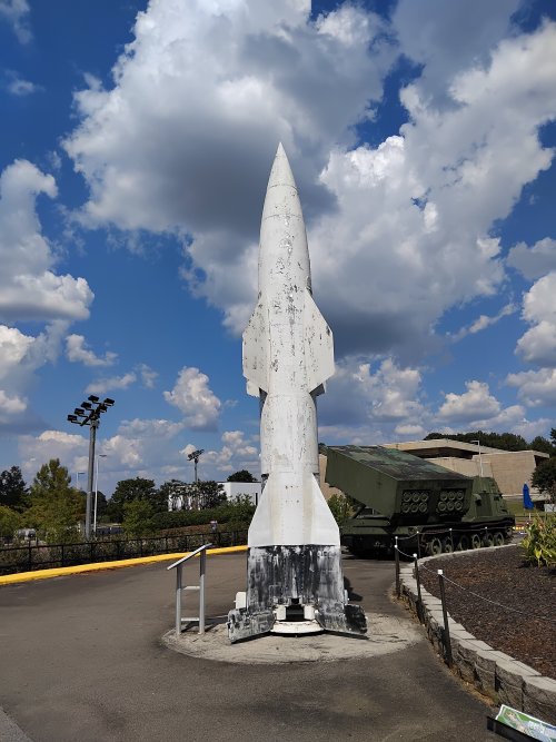
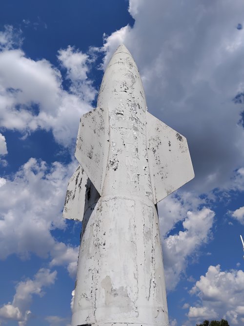
This beautiful thing isnt Wasserfall, but is a Hermes A1. On display at the Space and Rocket Center at Huntsville Alabama. Seems quite well preserved but sorely in need of a coat of paint.

Sporting the Wasserfall aerodynamic form with US developed internals.

While not being quite the same, it gives a good feel of what Wasserfall in launch position would have been like.
 

Attachments

  • IMG_20250915_143725.jpg
    IMG_20250915_143725.jpg
    2.4 MB · Views: 61
  • IMG_20250915_143046.jpg
    IMG_20250915_143046.jpg
    1.9 MB · Views: 67
July 10, 1944 - July 15, 1944
Meeting at Wa Prüf (BuM) 1
Wa Prüf (BuM) 1 reports that an inquiry has been received from T 3 with approximately the following content:

The question to be assessed is whether, in Project "W," the tail unit with its internal components is slowed down by the main explosive charge to such an extent that it is no longer suitable for engaging the enemy. After being informed of the approximate dimensions and speeds, Dr. Hoppe is of the opinion that the mass of the tail unit, in the form of a rather pointed cone, should continue to propel itself forward without being slowed down and should therefore also be used for target engagement.

Source:
Bundesarchiv Files
Signatur: RH 8/1264; Page: 136
Direct Link:
https://invenio.bundesarchiv.de/invenio/direktlink/d72f1270-5f13-40b8-bea4-6715fd4128df/


Codenames for Wasserfall
February 23, 1944
Signatur: RH 8/3105; Page: 29 -36
Direct Link:
https://invenio.bundesarchiv.de/invenio/direktlink/381a44f9-d19c-4f53-ac44-8a2b6e391f88/

Organizational chart of the Elektromechanische Werke GmbH
(October 10, 1944)
Signatur: RH 8/1263
Direct Link:
https://invenio.bundesarchiv.de/invenio/direktlink/6c0fd76c-7eb6-4981-a4be-360b02a3b7ae/
 
Last edited:
What was stopping them?
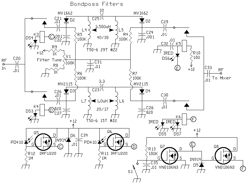
Tube technology for one. Tubes don't do well with very fine frequency bands. They tend to leak and drift as they age, heat, and cool. There's also the space issue in AAMs. The circuits are simple enough on their own

Band-Pass-Filter-Circuit-Diagram-030.jpg


The simplest ones only use resistors, coils, and capacitors, but they don't pass a narrow range of frequencies. When you start tossing in an op amp, things get complicated with tubes.

Imagine this in a missile to allow several specific frequencies of light to pass through while rejecting other wavelengths. Remember, in the 1940's to 60's those diodes would be a tube each. Solid state diodes weren't in use yet.

elrnbpfsch.gif


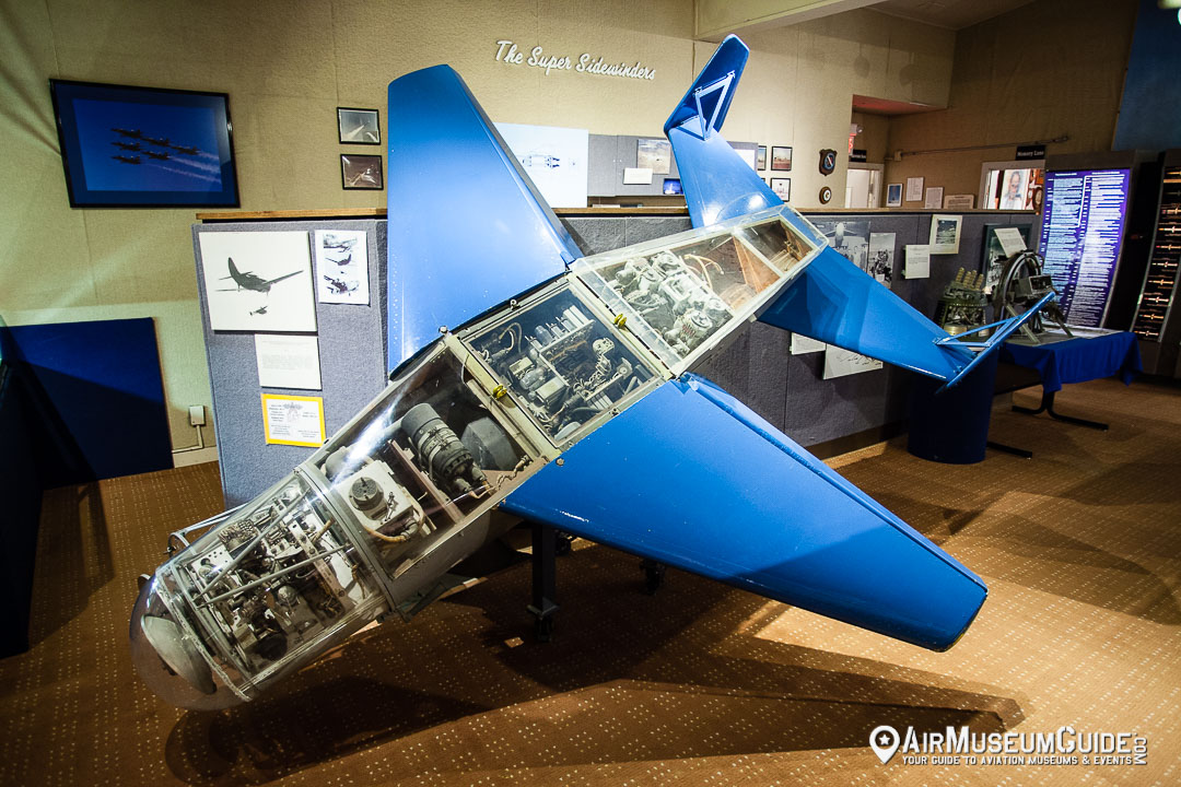
While this is a BAT glide bomb, look at the mass of electronics and their size that were required for it to home on a target using radar

NAWSChinaLake_MG_3203.jpg
 
The simplest ones only use resistors, coils, and capacitors, but they don't pass a narrow range of frequencies. When you start tossing in an op amp, things get complicated with tubes.
OK, I get you now. If LRC circuits won't cut it and you have to use tubes... yeah.
Which aviation museum is that?
 
Imagine this in a missile to allow several specific frequencies of light to pass through while rejecting other wavelengths. Remember, in the 1940's to 60's those diodes would be a tube each. Solid state diodes weren't in use yet.

During WW 2 there were already solid state (i.e. crystal) diodes, a lot of development was made at MIT.
In Germany, Herbert F. Matare worked at Telefunken developing crystal mixers for radar, starting from crystal rectifiers.
A couple of papers as references:
Breakthroughs Recalled on Transistor Precursors in Germany, France
Research on Silicon and Germanium in World War II

The 457-pages book about Crystal Rectifiers (Vol. 15 of the fantastic MIT Rad Lab series) is a summa of the work done in the USA during WW2. Some other info in Vol. 16 about Microwave Mixers.
 
During WW 2 there were already solid state (i.e. crystal) diodes, a lot of development was made at MIT.
In Germany, Herbert F. Matare worked at Telefunken developing crystal mixers for radar, starting from crystal rectifiers.
A couple of papers as references:
Breakthroughs Recalled on Transistor Precursors in Germany, France
Research on Silicon and Germanium in World War II

The 457-pages book about Crystal Rectifiers (Vol. 15 of the fantastic MIT Rad Lab series) is a summa of the work done in the USA during WW2. Some other info in Vol. 16 about Microwave Mixers.
But that doesn't translate into widespread use. In any case, the need here is for a bandpass filter with a very narrow range of specific frequencies for use in an expendable missile.
 
On the Kramer X-4 thread a discussion started on why the Wasserfall was fuelled in the horizonral position and then erected....

NickNick said...

"I guess this method allowed to do all the preparation in a shelter. The rocket could have been transported in an horizontal position to a choosen starting ground on a single truck. The starting procidure would have required very little time compared to the A4 and minimized the risk of beeing attaced during this period.

The structure of the rocket was surely somewhat strengthened compared to the A4 so that the bending stresses could be handled."
 
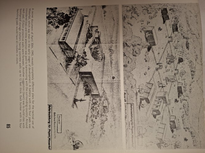
Wasserfall was designed for deployment from fixed flak batteries. So... many rockets, stored upright and loaded with propellant and warhead in some kind of shelter, awaiting use. Each standing on their own wheeled launch trolley. Rails were provided to push each upright missile a short distance outside to one of the launch pits for firing. This approach was adopted to allow a much shorter response time and higher rate of fire compared to the A4. This is described in the 1943 technical proposal document. Ive attached an image from the proposal, as presented in Klee and Merk "The birth of the missile".

I dont know how the lateral strength of Wasserfall compares with the A4. Greater i would guess, in that:
- it would have to withstand handling with a full propellant load.
- it was stressed to pull a 12G turn in flight in pursuit of its target, without buckling or shedding its wings.
- it had to withstand the nitrogen gas pressure in the propellant tanks (which formed the monocoque mid-section of the missile) without deforming or bursting.

We still have the original stress design reports, produced by Engineer Emil Hellebrand.
 

Attachments

  • 17803424196873484700960707129551.jpg
    17803424196873484700960707129551.jpg
    2.7 MB · Views: 55
Last edited:
When searching online, I stumbled across a CIA Information Report on post-war work in the USSR that mentions infrared homing for Wasserfall in the Footnotes at the end. I was actually looking for information on the Kiel-Z infrared detection system for German night-fighters, which also got a mention. The relevant Footnotes are below and the full report is at the following link CIA SOVIET DOCUMENTS COLLECTION

CIA Information Report on “Infrared Activities at Zavod 393, Krasnogorsk”. Dated 5 Feb 1954.

Footnote 1: Description of German Homing Missile Heads Utilizing Zeiss Optics.
a. Wasserfall is a lens mirror system, with a lead sulphide photocell. The field is divided into four quadrants each of which is obscured by two revolving shutters to give a pair of characteristic frequency interruptions. Each shutter wheel has two sets of spokes spaced at different frequencies and each set travels over half the aperture. The circumference of the two wheels are at right angles where they pass over the aperture. Thus the quadrant in which the target falls is “defined by the frequency characteristic of the signal and the mechanism responds accordingly by correcting the course of ‘the missile.

Footnote 2: The German Kiel Geraet was originally designed as a bomber exhaust “detector for night fighters. Zeiss, Jena, received orders for 50 “Kiel devices in the autumn of 1944 from Dr. PLUMEYER of OKL. Twenty to thirty of these were delivered to the German Air Force. Tests were made at Réchlin and a squadron at Goslar was fitted. The main difference of Kiel I, II, III and IV was in the field of view, After some minor modifications and the use of more sensitive amplifiers, this identical Kiel IV has become currently the work horse for passive detection of both air and ground targets. It is in use by both the Air Force and the Signal Corps for experimental purposes and can be considered a highly useful instrument.
 
When searching online, I stumbled across a CIA Information Report on post-war work in the USSR that mentions infrared homing for Wasserfall in the Footnotes at the end. I was actually looking for information on the Kiel-Z infrared detection system for German night-fighters, which also got a mention. The relevant Footnotes are below and the full report is at the following link CIA SOVIET DOCUMENTS COLLECTION

CIA Information Report on “Infrared Activities at Zavod 393, Krasnogorsk”. Dated 5 Feb 1954.

Footnote 1: Description of German Homing Missile Heads Utilizing Zeiss Optics.
a. Wasserfall is a lens mirror system, with a lead sulphide photocell. The field is divided into four quadrants each of which is obscured by two revolving shutters to give a pair of characteristic frequency interruptions. Each shutter wheel has two sets of spokes spaced at different frequencies and each set travels over half the aperture. The circumference of the two wheels are at right angles where they pass over the aperture. Thus the quadrant in which the target falls is “defined by the frequency characteristic of the signal and the mechanism responds accordingly by correcting the course of ‘the missile.

Footnote 2: The German Kiel Geraet was originally designed as a bomber exhaust “detector for night fighters. Zeiss, Jena, received orders for 50 “Kiel devices in the autumn of 1944 from Dr. PLUMEYER of OKL. Twenty to thirty of these were delivered to the German Air Force. Tests were made at Réchlin and a squadron at Goslar was fitted. The main difference of Kiel I, II, III and IV was in the field of view, After some minor modifications and the use of more sensitive amplifiers, this identical Kiel IV has become currently the work horse for passive detection of both air and ground targets. It is in use by both the Air Force and the Signal Corps for experimental purposes and can be considered a highly useful instrument.
Interesting. Did you find any other evidence for the existence of an infrared detector cslled Kiel ? It seems an especially awful code name for an IR device, given Elac did so much work on these and their home was Kiel. Like calling the "Manhattan Project" the "Los Alamos project" :)

In some of von Brauns early Flak proposals he describes and diagrams a thing called the Spanner Geraet. Apparently fitted to some night fighters for a while. But this is an IR image intensifier, with an IR spotlight, rather than passive IR detection. It was von Brauns first proposal for IR terminal homing of the Flak rocket that eventually became Wasserfall. Superceeded later by several teams working on slotted scanner PbS cell passive IR homing, including Dr Weiss team at Peenemunde under von Braun.
 
Last edited:
Wasserfall was designed for deployment from fixed flak batteries. So... many rockets, stored upright and loaded with propellant and warhead in some kind of shelter, awaiting use. Each standing on their own wheeled launch trolley. Rails were provided to push each upright missile a short distance outside to one of the launch pits for firing. This approach was adopted to allow a much shorter response time and higher rate of fire compared to the A4. This is described in the 1943 technical proposal document. Ive attached an image from the proposal, as presented in Klee and Merk "The birth of the missile".

I dont know how the lateral strength of Wasserfall compares with the A4. Greater i would guess, in that:
- it would have to withstand handling with a full propellant load.
- it was stressed to pull a 12G turn in flight in pursuit of its target, without buckling or shedding its wings.
- it had to withstand the nitrogen gas pressure in the propellant tanks (which formed the monocoque mid-section of the missile) without deforming or bursting.

We still have the original stress design reports, produced by Engineer Emil Hellebrand.

Actually, the nitrogen gas pressure might have helped to prevent buckling and bending. The gas tank was an integral part of the fuselage and internal pressure would have kept in form, just like a baloon or blimp.
 
Actually, the nitrogen gas pressure might have helped to prevent buckling and bending. The gas tank was an integral part of the fuselage and internal pressure would have kept in form, just like a baloon or blimp.
I thought that too. But the pressure is not always there. Before launch, the nitrogen gas is only in the high pressure sphere, which is separate from (though obviously attached to) the external skin. There is no gas pressure (above ambient) applied to the monocoque propellant tanks until the missile is committed to launch. So any rigidity gain from gas pressure in propellant tanks is not available during ground handling.

Similarly after motor burnout the nitrogen is exhausted, leaving the empty tanks back at ambient pressure. Still with up to 45 seconds of unpowered flight to go. So the stress calculations didnt include the potential benefit of pressurised tanks.
 
Actually, the nitrogen gas pressure might have helped to prevent buckling and bending. The gas tank was an integral part of the fuselage and internal pressure would have kept in form, just like a baloon or blimp.
The skin of the Wasserfall was sufficiently strong enough, and fully rigid that the nitrogen gas really doesn't add anything in terms of structural strength. The big concern with respect to the fuel tanks the Germans had was getting all the fuel out of them as the Wasserfall maneuvered. Unlike the A-4 where this wasn't an issue as the missile went straight up (more or less), with the Wasserfall, it maneuvered into different flight positions.

The Germans, apparently for lack of suitable materials, didn't use a bladder system like many postwar missiles did. That is, the fuel was in a rubber (or similar material) bag that collapsed as pressure was applied forcing all of the fuel out of the tank. Instead, the Germans went with several designs for a scavenger system before settling on one that used a swing arm with a pickup that would empty, or close to empty, the tank.

Balloon tanks, like on say the US MX 774 HIROC, were not considered for the Wasserfall.
 
How can you proove this? Internal pressure is very efficient against buckling and even without knowing the exect shape, I'm shure it was a barrel shaped or cylindrical tank. I don't know how you define a baloon tank, my guess is that you mean a spherical tank. A spherical tank is not suited as outer surface or load bearing structure. A barral shaped tank can partially become a part of the outer surface and is well suited as load bearing structure. With pressurisation, all the struts and rips which are usually required oj an outer surface can be avoided.
 
How can you proove this? Internal pressure is very efficient against buckling and even without knowing the exect shape, I'm shure it was a barrel shaped or cylindrical tank. I don't know how you define a baloon tank, my guess is that you mean a spherical tank. A spherical tank is not suited as outer surface or load bearing structure. A barral shaped tank can partially become a part of the outer surface and is well suited as load bearing structure. With pressurisation, all the struts and rips which are usually required oj an outer surface can be avoided.
On the Wasserfall, the tanks were designed with a front and rear cap with the sides being the skin of the missile. That skin was rigid on its own by the thickness of the material. That is, full or empty, the missile was structurally rigid.

On MX 774, as an example, the wall of the missile was relatively thin material and when the fuel / oxidizer tanks were full, nitrogen was used to pressurize them and make them stiff and rigid much like an unopened can of soda pop today is.

With Wasserfall, maneuvering of the missile was expected, so the balloon-type tank couldn't be used like it was in some post-war ballistic missiles where maneuvering was minimal and reentry was not occurring (eg., a detachable warhead was used).
 
Interesting. Did you find any other evidence for the existence of an infrared detector cslled Kiel ? It seems an especially awful code name for an IR device, given Elac did so much work on these and their home was Kiel. Like calling the "Manhattan Project" the "Los Alamos project" :)

In some of von Brauns early Flak proposals he describes and diagrams a thing called the Spanner Geraet. Apparently fitted to some night fighters for a while. But this is an IR image intensifier, with an IR spotlight, rather than passive IR detection. It was von Brauns first proposal for IR terminal homing of the Flak rocket that eventually became Wasserfall. Superceeded later by several teams working on slotted scanner PbS cell passive IR homing, including Dr Weiss team at Peenemunde under von Braun.
The Kiel Z I/II was originally proposed as a Flak missile homer, according to Fritz Trenkle.
 
Back
Top Bottom