
Dagger
ACCESS: Secret
- Joined
- 24 December 2019
- Messages
- 399
- Reaction score
- 786
It's not really offtopic as the topic title nowadays is:
The Secret Horsepower Race by Calum Douglas (and piston engine discussion)
Note that I was referring to the DB engine which, due to its variable speed drive, should also below FTH benefit from ram pressure.
Apparently you are now referring to Hooker's booklet on the Merlin XX engine, which does not have a variable speed drive and therefore does not benefit from ram pressure below FTH. In any case there are many inaccuracies in that booklet. Going into those here would be offtopic.
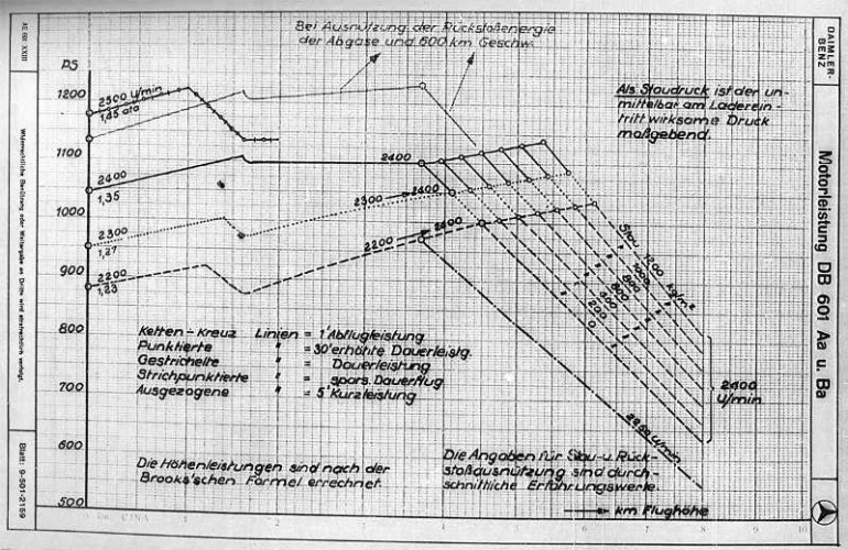
") , but from 2,1 km on the 2nd pump (Zuteilpumpe) starts to increase oil quantity in the coupling, so supercharger rpm and so the pressure increases. In theory, the excess pressure shouldn't be as pronounced, see this graph from BA R3/3827 (downloadable from Invenio):
, but from 2,1 km on the 2nd pump (Zuteilpumpe) starts to increase oil quantity in the coupling, so supercharger rpm and so the pressure increases. In theory, the excess pressure shouldn't be as pronounced, see this graph from BA R3/3827 (downloadable from Invenio):
