UPS MD-11 crash

The wing clevis looks like a massive steel part, compared to that the aluminium lugs look quite flimsy, but of course, someone will have done the math back than. after more than 30 years of operation, fatigue failures is aluminium parts are a part of the statistics. Unlike steel, the durability of Aluminium is shrinking with every cycle.

Many older 747 are using the same jets, so this accident can also have a much larger impact on the 747 freighter fleet (I had a personal first hand info from a 747 freighter pilot).
 
There have been a few other cases of incipient failures not detected before catastrophe. Most famously the Impossible Landing in Sioux City.

Yeah though in that case it was a titanium billet rejected by quality control at GE due to a manufacturing defect and sent for recycling according to its serial number that somehow found its way back into the supply chain as a rotor disk manufactured by GE with incorrect paperwork (in the records being listed as coming from an external part supplier two years before they even started manufacturing titanium parts). The part was estimated to have a life of 54,000 cycles so the FAA set the inspection interval as 18,000 cycles but it failed after 18 years at 16,899 cycles. However despite the required inspection interval not being reached the part had actually been inspected six times during engine heavy overhauls and the die from its last testing was still present showing a 0.5 inch long crack in the rotor disk that should have been easily caught if the maintenance crew were doing their job properly.
 
Last edited:
Looking at photo 3 here--
https://pbs.twimg.com/media/G6NXIEZacAEsdlP?format=jpg&name=largeCould that be the pylon acting like a can-opener up top?
https://www.faa.gov/sites/faa.gov/f...arned/N110AA/lgChicagoDC-10_fig06_cutaway.jpg
Not enough data points for any real conclusions---but it seems like the same nacelle position each time. Why might that be? Just bad luck?

Would top mount nacelle positions be less dangerous, if more noisy?
https://www.facebook.com/engineerin...arge-engine-nacelles-was-one/853005927272990/
Resources
https://blog.gridpro.com/engine-nacelle-aerodynamics/https://phys.org/news/2025-11-ai-turbulence-fresh-unsolved-physics.htmlMaybe A.I. may finally be of use here
https://techxplore.com/news/2025-11-large-language-qa-aerospace.html
Elsewhere on the site, there was some talk about converting tri-jets to twin-jets. Might that be an opportunity to look at the wings?
 
Last edited:
Nightmarish timing, right as they're lifting off.

Is there any such thing as a good time for the engine to fall off? Pretty no matter when that happened there's a pretty good chance of at minimum a complete loss of the aircraft, and while more altitude would delay the issue, if #2 eats debris or the loss of #1 causes fatal wing structural/fire/hydraulic/electrical system damage the bird is going down.

Not enough data points for any real conclusions---but it seems like the same nacelle position each time. Why might that be? Just bad luck?

Would top mount nacelle positions be less dangerous, if more noisy?

Elsewhere on the site, there was some talk about converting tri-jets to twin-jets. Might that be an opportunity to look at the wings?

Yes, both DC-10 type pylon failures were the same side, but that doesn't mean much when there's 2 occurrences and 2 options.

Engine separation is so incredibly rare and damaging that discussing more or less dangerous is a bit like discussing which direction to face while getting struck by lightening - it's sufficiently improbable to not be worth the worry, and more or less irrelevant to the final outcome.

Zero chance of converting to twin. You'd need to pretty much completely redesign, rebuild and recertify the aircraft.
 
The the remaining DC-10 fleet (I refuse to call them "MD-11"s) need that anyway at this point.
 
If the number one engine had torn off, say, 30 seconds later when the MD-11 a few hundred feet in height about travelling ~300knots (I suppose the flaps and landing gear would be up) could the flight-crew have had time to keep control of their aircraft and be able to circle around for an emergency landing?
 
Last edited:
The aircraft can fly on two engines but not one, when the engine ripped off it took out the central engine so in the same situation it would have still been left with a heavily laden aircraft with not enough power to maintain airspeed. So no unless it was already at altitude and the runway was clear for an emergency approach I think it was still going to crash before it could circle to return to the runway. If the second engine was still operational then in theory it could have still gained altitude, dumped fuel then made an emergency landing.
 
Last edited:
Which is why the blanket grounding. The rear pylon mount is a single point of failure for the whole MD-11, DC-10 type, a single point of failure which is most likely to give way *on rotation* as it did with the UPS flight.

10 Tankers operate 4 DC-10s as air tankers as well, so this incident has impacts on global forest fire fighting capability as well.
 
If the number one engine had torn off, say, 30 seconds later when the MD-11 a few hundred in height about travelling ~300knots (I suppose the flaps and landing gear would be up) could the flight-crew have had time to keep control of their aircraft and be able to circle around for an emergency landing?
Maybe, but it also seems like failure wasn't going to happen unless it happened then and there. AA191's engine also came off right at rotation, though in that case the fatal damage was the engine damaging the wing rather than taking out Engine 2.
 
Which is why the blanket grounding. The rear pylon mount is a single point of failure for the whole MD-11, DC-10 type, a single point of failure which is most likely to give way *on rotation* as it did with the UPS flight.

10 Tankers operate 4 DC-10s as air tankers as well, so this incident has impacts on global forest fire fighting capability as well.
There are already planes back in the air. The AD "check for cracks" boiled down to "overtorque the bolt and replace it if it breaks"
 
Elsewhere on the site, there was some talk about converting tri-jets to twin-jets. Might that be an opportunity to look at the wings?
The DC-10/MD-11 was already on the verge of retirement before the crash. UPS planned to withdraw them in a couple of years, and their 27 are half the MD-11s flying, Fedex has almost as many, 25, and had planned to withdrawn them in 2028, but then decided the market justified running them on until 2032. That business case isn't going to work with any significant maintenance/repair outlay.
 
My Father was flying DC-10s with United Air Lines at the time of the American Airlines DC-10 crash at O'Hare. I had a cousin and his family on that flight too.

A couple of months after the AA crash, my Father went thru recurrent training and one of the scenarios thrown at them in the simulator was just that - loss of the engine (quite literally) like at O'Hare. He said the first attempt ended with the same result as the effort to climb vs. gaining air speed was the wrong trade off. A later effort in the simulator was successful but only because they had practiced it. Like the DC-10 at O'Hare, the MD-11 crew could not see the left (or right) engine from the cockpit.

Enjoy the Day! Mark
 
The DC-10/MD-11 was already on the verge of retirement before the crash. UPS planned to withdraw them in a couple of years, and their 27 are half the MD-11s flying, Fedex has almost as many, 25, and had planned to withdrawn them in 2028, but then decided the market justified running them on until 2032. That business case isn't going to work with any significant maintenance/repair outlay.
As I said, if you can overtorque the mounting bolt and it breaks, you replace it.

It's a relatively cheap fix, only a couple hours of labor from maybe two mechanics and maybe a new bolt.
 
How does it work? It is a closed 360 degree ring structure without any bolt holding it together.
 
Last edited:
How does it work? It is a closed 360 degree ring structure without any bolt holding it together.
What goes through that ring? A bolt. A very big bolt, since it has to hold takeoff thrust.

Once the engine mounting bolts failed, they allowed the spherical bearing to come apart due to differential loadings on it.
 
What goes through that ring? A bolt. A very big bolt, since it has to hold takeoff thrust.

Once the engine mounting bolts failed, they allowed the spherical bearing to come apart due to differential loadings on it.
Well I can't open the pics in the moment, but I don't believe, the axial forces of the bolt will act on the aluminium lugs. There must have been a sleeve inside or a step in the bolt on the nut side which does this job, otherwise there would have been a way to high bending force from the side of the lugs. This would be a catastrophic design which wouldn't have lasted for a single take off. Keep in mind, that the spherical bearing needs to be moving around freely, otherwise it wouldn't have been spherical.

Edit, here we can see the arrangement. The axial forces (thrust) )were not transmitted by this structure and the bolt/spherical bearing surly had some axial play to compensate heat expansion.
 

Attachments

  • Wing_attachment.jpg
    Wing_attachment.jpg
    111.7 KB · Views: 33
Last edited:
How would these bolts compare to those used to attach an ET to an orbiter? They only need to work once. When I see failures like this, it does make me wince a a bit about some RLV designs, though in-line designs spread out loads.

What about additional composites? If a nacelle bolt snaps, fibers keep it hanging on by a thread such that it just drags and doesn’t flip out and impale something.

Better for parts to fail in a preferable manner if they fail at all.
 
Last edited:
How would these bolts compare to those used to attach an ET to an orbiter? They only need to work once. When I see failures like this, it does make me wince a a bit about some RLV designs, though in-line designs spread out loads.

What about additional composites? If a nacelle bolt snaps, fibers keep it hanging on by a thread such that it just drags and doesn’t flip out and impale something.

Better for parts to fail in a preferable manner if they fail at all.

If you would have become an engineer, you wouldn't be able to design a hole puncher without getting lost in hundreds of overly complicate variants with exotic materials.
 
Well I can't open the pics in the moment, but I don't believe, the axial forces of the bolt will act on the aluminium lugs. There must have been a sleeve inside or a step in the bolt on the nut side which does this job, otherwise there would have been a way to high bending force from the side of the lugs. This would be a catastrophic design which wouldn't have lasted for a single take off. Keep in mind, that the spherical bearing needs to be moving around freely, otherwise it wouldn't have been spherical.

Edit, here we can see the arrangement. The axial forces (thrust) )were not transmitted by this structure and the bolt/spherical bearing surly had some axial play to compensate heat expansion.
Oh, they go together that way. Too used to 727s which had the engine cradle bolted to the airframe and 4 bolts holding the engine to the cradle, sorry.

Alright, the thrust link does carry some of the thrust loads. Other thrust loads are carried the length of the bolts in those spherical joints, trying to either rip the heads off the bolts or the nuts off depending on how the instructions tell you to put those bolts in.

But again, the fix in the AD was to overtorque the bolts, and replace all those bolts that broke. I suspect that was thought to be limited enough now to allow some Boeing machine shops to spin up a fresh batch of those bolts to replace all bolts currently in service later on. If there even is a "later" for the MD11s.


How would these bolts compare to those used to attach an ET to an orbiter? They only need to work once. When I see failures like this, it does make me wince a a bit about some RLV designs, though in-line designs spread out loads.
The bolts that held the ET to the orbiter were explosive.

I don't think you can pay civilian folks enough money to work around major league pyrotechnics. (Crud, you can't pay me enough to work around airbags!)


What about additional composites? If a nacelle bolt snaps, fibers keep it hanging on by a thread such that it just drags and doesn’t flip out and impale something.
You're supposed to be able to disassemble the pylon from the wing. IIRC there's some inspections that the pylons are in the way of doing.


Better for parts to fail in a preferable manner if they fail at all.
This is the preferable manner for those parts to fail.

The engine is required to separate from the wing in the event of a wheels-up landing.
 
Oh, they go together that way. Too used to 727s which had the engine cradle bolted to the airframe and 4 bolts holding the engine to the cradle, sorry.

Alright, the thrust link does carry some of the thrust loads. Other thrust loads are carried the length of the bolts in those spherical joints, trying to either rip the heads off the bolts or the nuts off depending on how the instructions tell you to put those bolts in.

But again, the fix in the AD was to overtorque the bolts, and replace all those bolts that broke. I suspect that was thought to be limited enough now to allow some Boeing machine shops to spin up a fresh batch of those bolts to replace all bolts currently in service later on. If there even is a "later" for the MD11s.

I don't believe it, there is a thrust link for the thrust and little doubt about it's function. They use all the ball bearings for a specific reason, which is having well predictable loads in the structure.

Over torquing the bolt wouldn't even apply any load into the direction they cracked, but would instead leave some imprints if the axial load would even reach the lugs. The lugs would be bended inwards instead of breaking from a tangential load, this totally doesn't make sense.
 
Yeah doesn't make sense to me either, its essentially a ball and socket joint with the lug that forms part of the socket failing, over tightening the fastening bolts doesn't directly apply pressure to the part that failed, though it would potentially constrict the bearings and reduce the ability of the two lugs to rub against each other. Doesn't look like Boeings inspection test has been approved by the FAA either.

Western Global has just (last Friday) furloughed all its MD-11 pilots so they aren't seeing a quick return to service.

“During the past two weeks, WGA has been in constant communication with Boeing, who originally anticipated that by Nov. 14 they would have an approved noninvasive inspection protocol to return the aircraft to service. Because of this, we were hopeful that the MD-11 grounding would be short-lived. However, Boeing has now advised that more and highly invasive inspections, as well as repairs and parts replacements, would be required, resulting in an extended grounding of the MD-11 fleet for an undeterminable period of time,”
 
Last edited:
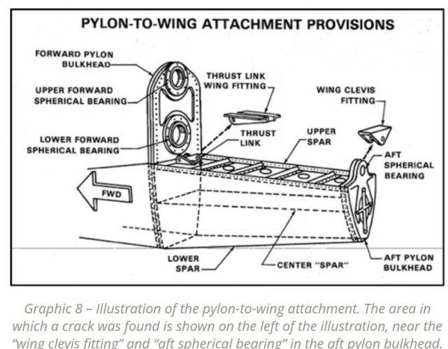
There are 4 things that hold the pylon onto the wing: 2 big spherical bearings forward, the thrust link, and the smaller aft spherical bearing. That's it.

Since the whole pylon came loose with the engine, we don't care about the bolts attaching engine to pylon at this time.

Let's say the thrust link lets go (or bolts on the thrust link, same result different cause). Now all the thrust loads are going through the spherical bearings, and the engine is going to attempt to go nose-up because it's only restrained on one side of the engine. That force tries to pull the aft spherical bearing down and rip the aft spherical bearing apart. Once the aft thrust bearing rips apart, the forward two spherical bearings rotate a lot more and then the bolts through them start hitting the side of the bearing and maybe pushing onto the forward bulkhead until they rip out/apart.

Also, note that Spherical bearings are not intended to take thrust loads. Due to how spherical bearings have to be designed, the race supporting the sphere has a knife edge that is (relatively) easy to deform under extreme abnormal loads. The design loads for a spherical bearing are perpendicular to the bearing.

This is worse if there's any space for the engine to move suddenly when one attach point fails suddenly, because now you're talking about shock loads instead of constant strain.

Did I get all sorts of confused about which bolts were getting overtorqued? Was it the Thrust Link bolts instead of the spherical bearing bolts?
 
In case there is some truth about the bolt story, it must be something totally different. It might be, that there is a way to adjust the bearing play in the lugs. This might be done, with a conical bolt in a conical sleeve. Here, it would in fact be possible to apply a radial load by overstretching the bolt.
 
The outer spherical bearing surface must be made in two parts to enable assembly (in some cases, other tricks are used). These two parts are hold together by the outer bearing casing. The casing must prevent them from any axial movement which can be critical, since every radial force will cause axial forces trying to push tjem out of the casing. This is the part of the design which failed and it is clearly insane that this failure was regarded as not safety relevant!
 
Helpful to actually have the NTSB Update linked.

TLDR: Boeing had seen four bearing race failures on three aircraft. In each case the bearing race split circumferentially into forward and aft halves, which visually protruded from the lugs. Boeing concluded it was not a safety of flight issue and could be checked at 60 month intervals. The check was to look for protruding race halves - i.e. for a bearing that had already failed. If an airline found a failed bearing race, Boeing had a revised design, but were perfectly happy for airlines to replace it with the old design.

*headdesk*
 
Last edited:
As I see it, the two halfs were only kept in position by beeing press fit. There was no cracking of any part necessary to bring the two halve out of position, just enough time with many load cycles and different heat expension between the steel and the aluminium. I wouldn't have beeb happy with this design, but how can anybody believe it is unproblematic whent these halves move out of the center?? It's like driving a car with the suspension having several mm play in the linkage system.
 
Video posted by the NTSB this morning (19-May-2026), regarding the UPS MD-11F crash, illustrating the failure of the aft pylon mount. The video concludes with the airport surveillance video of the No. 1 engine and pylon separating from the wing. Stills from this video have been featured in prior reports.
YouTube - NTSB Animation - Engine-to-Wing Attachment Design Overview and Findings
 
If the bearing race would have been a single part, there would have been no way to get the inner spherical ball joint into the outer race. Those bearings are usually made with a split outer bearing race which sits in an housing which hold everything together. Some important information is missing here, were those two halves welded together after installing the inner sphere?
 
If the bearing race would have been a single part, there would have been no way to get the inner spherical ball joint into the outer race. Those bearings are usually made with a split outer bearing race which sits in an housing which hold everything together. Some important information is missing here, were those two halves welded together after installing the inner sphere?
IIRC the race is heated up and the bearing is cooled in liquid nitrogen to assemble them.
 
This method is good for a gab of, let's say 0.3 mm, but here we need to overcome several mm between the entry diameter and the spherical diameter.
 

Similar threads

Back
Top Bottom
